EP1531315A2 - Header tank with integral mounting flange - Google Patents
Header tank with integral mounting flange Download PDFInfo
- Publication number
- EP1531315A2 EP1531315A2 EP04078143A EP04078143A EP1531315A2 EP 1531315 A2 EP1531315 A2 EP 1531315A2 EP 04078143 A EP04078143 A EP 04078143A EP 04078143 A EP04078143 A EP 04078143A EP 1531315 A2 EP1531315 A2 EP 1531315A2
- Authority
- EP
- European Patent Office
- Prior art keywords
- tank
- wall
- joint
- tab
- flange
- Prior art date
- Legal status (The legal status is an assumption and is not a legal conclusion. Google has not performed a legal analysis and makes no representation as to the accuracy of the status listed.)
- Granted
Links
Images

Classifications
-
- F—MECHANICAL ENGINEERING; LIGHTING; HEATING; WEAPONS; BLASTING
- F28—HEAT EXCHANGE IN GENERAL
- F28F—DETAILS OF HEAT-EXCHANGE AND HEAT-TRANSFER APPARATUS, OF GENERAL APPLICATION
- F28F9/00—Casings; Header boxes; Auxiliary supports for elements; Auxiliary members within casings
- F28F9/001—Casings in the form of plate-like arrangements; Frames enclosing a heat exchange core
- F28F9/002—Casings in the form of plate-like arrangements; Frames enclosing a heat exchange core with fastening means for other structures
-
- F—MECHANICAL ENGINEERING; LIGHTING; HEATING; WEAPONS; BLASTING
- F28—HEAT EXCHANGE IN GENERAL
- F28F—DETAILS OF HEAT-EXCHANGE AND HEAT-TRANSFER APPARATUS, OF GENERAL APPLICATION
- F28F9/00—Casings; Header boxes; Auxiliary supports for elements; Auxiliary members within casings
- F28F9/02—Header boxes; End plates
-
- Y—GENERAL TAGGING OF NEW TECHNOLOGICAL DEVELOPMENTS; GENERAL TAGGING OF CROSS-SECTIONAL TECHNOLOGIES SPANNING OVER SEVERAL SECTIONS OF THE IPC; TECHNICAL SUBJECTS COVERED BY FORMER USPC CROSS-REFERENCE ART COLLECTIONS [XRACs] AND DIGESTS
- Y10—TECHNICAL SUBJECTS COVERED BY FORMER USPC
- Y10T—TECHNICAL SUBJECTS COVERED BY FORMER US CLASSIFICATION
- Y10T29/00—Metal working
- Y10T29/49—Method of mechanical manufacture
- Y10T29/4935—Heat exchanger or boiler making
- Y10T29/49389—Header or manifold making
Definitions
- the subject invention relates to a one-piece aluminium heat exchanger tank and a method for fabricating such a tank.
- Various heat exchanger tanks exist in the art that are formed from a single sheet of metallic material. These one-piece tanks are typically fabricated by rolling an aluminum-clad sheet into a structure having integrally formed sidewalls and then joining two opposed side edges of the walls together along a common joint. The resulting tank is then connected to a core subassembly using conventional nuts and gasket seals in combination with discrete mounting brackets that must be positioned on the tank before the tank is connected to the core.
- tank Although forming a single, overlapping joint on the exterior of the Kobayashi et al., tank arguably reduces the number of steps required to fabricate the tank, it does nothing to minimize the space occupied by the tank once it has been connected to a core subassembly. It also creates a rough, marred exterior surface which is so uneven that it renders the tank unuseable. Furthermore, the process of connecting the tank to the core is complicated by the use of the discrete mounting brackets. Each bracket must be separately brazed to the exterior of the tank before the tank can be attached to the core.
- references specifically disclose aluminum tanks having brazed joints and which are mounted onto cores using separate brackets, the references fail to provide any type of connecting joints that are strong, yet result in a tank having a space-saving and smooth exterior surface.
- the references also do not disclose a tank featuring such a joint in combination with an integrally-formed bracket or rail for use in connecting the tank to a core.
- the invention provides a heat exchanger tank formed from a single sheet of clad material.
- the sheet extends through a rectangular cross-section and defines a tube wall with tube holes extending therethrough.
- a parallel joint wall is spaced from the tube wall. Spaced parallel sidewalls interconnect the joint and tube walls to define a chamber and opposed open ends.
- the joint wall has an integrally formed tab that extends therefrom into the chamber. A first of the sidewalls is disposed in sealing engagement with the outside of the tab to enclose the tab within the chamber.
- the subject invention also provides a method of fabricating a heat exchanger tank.
- the method includes the step of forming a single sheet of material with a cladding on at least one surface thereof to define a tank extending through a rectangular cross-section and having a tube wall, a parallel joint wall spaced from the tube wall, and spaced parallel sidewalls interconnecting the joint and tube walls to define a chamber having opposed open ends.
- An additional step is forming an integral tab extending from the joint wall into the chamber.
- a first of the sidewalls is disposed into engagement with the exterior of the tab to enclose the tab within the chamber, and brazing the first sidewall to the tab.
- the subject invention overcomes the limitations of the related art by providing a one-piece heat exchanger tank specifically designed to minimize the exterior surface area occupied by the tank after it has been installed on a radiator core. This is achieved by providing a smooth exterior surface created by joining the opposed side edges of the tank in a manner that positions the overlapped edges inside the chamber of the tank, and by incorporating an integrally-formed mounting bracket on the tank without jeopardizing the leak integrity of the tank.
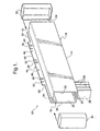
- a heat exchanger tank for a cooling system is shown generally at 10 in Figure 1, and at 110 in Figure 6.
- the tank is formed from a single sheet of material having a cladding 12 on at least one surface thereof.
- the sheet material shown in the Figures is aluminum sheet material with 4000 series braze on the exterior surface thereof.
- the sheet extends through a rectangular cross-section to define a tube wall 14 and a parallel joint wall 16 spaced therefrom. Spaced parallel sidewalls 18 interconnect the joint wall 16 and tube wall 14 to define a chamber 20 and opposed open ends 22, 24 for permitting fluid flow through the tank 10 .
- the tube wall 14 includes tube holes 25 through which elongate tubes 26 are received.
- Each of the tubes 26 defines a passage 28 which extends through the tube 26 to permit fluid flow into the chamber 20 .
- End caps 30, 32 are positioned for being sealingly engaged with the open ends 22, 24 of the tank.
- Each tank also includes a tab 34 integrally formed with the joint wall 16 .
- the tab 34 extends into the chamber 20 .
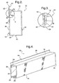
- a first sidewall 36 of the sidewalls 18 is disposed in sealing engagement with the outside of the tab 34 and encloses the tab 34 within the chamber 20 .
- the first sidewall 36 includes an interior joint surface 38 positioned within the chamber 20 .
- the tab 34 includes an exterior surface 40 with the cladding 12 thereon. The cladding 12 seals the exterior surface 40 into engagement with the joint surface 38 to define an internal braze joint 42 within the chamber 20 .
- the first sidewall 36 extends above the joint wall 16 and the tab 34 to define a mounting flange 44 .
- the flange 44 includes a plurality of holes 46 for receiving complementary fasteners therethrough for mounting the tank 10 on the cooling system.
- the flange 44 has a peripheral edge 48 from which spaced slots 50 extend toward the tab 34 . Like the holes 46 , the slots 50 are used to connect the tank 10 to the cooling system.
- Recessed areas 52, 54 extend from the peripheral edge 48 toward each of the ends 22, 24 of the tank for positioning the flange 44 in closely-conforming relation to the cooling system.
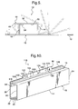
- a heat exchanger tank according to another embodiment of the invention is shown generally at 110 in Figure 6.
- the tank 110 includes the same components and is formed from the same materials as the tank 10 .
- the flange 44 of the tank 110 is formed from a double thickness of the sheet material to define primary and reinforcing walls 114 and 116 .
- the reinforcing wall 116 overlaps the primary wall 114 on the interior thereof and extends transversely over the joint wall 16 on the exterior thereof.
- the cladding 12 on the joint wall 16 seals the reinforcing wall 116 into engagement the joint wall 16 to define an exterior braze joint 118 .
- a U-shaped fold 120 integrally joins the reinforcing wall 116 with the primary wall 114 .
- the holes 122 , slots 124 and recessed areas 126 , 128 on the tank 110 are identical to the respective holes 46 , slots 50 and recessed areas 52, 54 of the tank 10 .
- the peripheral edge 130 from which the slots 124 extend is identical to the peripheral edge 48 of the tank 10 .
- the subject invention also includes a method of fabricating a heat exchanger tank.
- the method includes the steps of forming a single sheet of material having a cladding 12 on at least one surface thereof to define a tank 10 extending through a rectangular cross-section and having a tube wall 14 with a parallel joint wall 16 spaced from the tube wall 14 .
- Spaced parallel sidewalls 18 interconnect the joint and tube walls 16 and 14 to define a chamber 20 having opposed open ends 22, 24 .
- the joint wall 16 and tube wall 14 are interconnected by forming an integral tab 34 that extends from the joint wall 14 into the chamber 20 , and a first sidewall 36 of the sidewalls 18 is disposed into engagement with the exterior of the tab 34 to enclose the tab 34 within the chamber 20 .
- the first sidewall 36 is then brazed to the tab 34 .
- the method is further defined as extending the first sidewall 36 upwardly above the joint wall 14 and the tab 34 to project outwardly from the joint wall 14 to define a flange 44 .
- Still another step is extending holes 46 through the flange 44 for receiving fasteners therethrough to mount the tank 10 on the cooling system.
- Spaced slots 50 are also formed on the flange 44 and extend from a peripheral edge 48 thereof toward the tab 34 for connecting the tank 10 to the cooling system.
- the method includes the step of forming a recessed area 52, 54 on each end of the flange 44 that extends from the peripheral edge 44 thereof toward an adjacent end 22, 24 of the tank 10 .
- the method continues in an alternative way by doubling the sheet defining the flange 44 to further define a primary wall 114 and a reinforcing wall 116 .
- the method is further defined by forming a U-shaped fold 120 which integrally joins the primary wall 114 and reinforcing wall 116 .
- the method also includes the step of overlapping the primary wall 114 and the joint wall 16 with the reinforcing wall 116 .
- the reinforcing wall 116 is then brazed to the primary wall 114 and the joint wall 16 .
- a final step is sealing end caps 30, 32 with the open ends 22, 24 on each of the tanks 10, and 110.
Landscapes
- Engineering & Computer Science (AREA)
- Physics & Mathematics (AREA)
- Thermal Sciences (AREA)
- Mechanical Engineering (AREA)
- General Engineering & Computer Science (AREA)
- Details Of Heat-Exchange And Heat-Transfer (AREA)
- Filling Or Discharging Of Gas Storage Vessels (AREA)
- Piezo-Electric Or Mechanical Vibrators, Or Delay Or Filter Circuits (AREA)
Abstract
Description
Claims (22)
- A heat exchanger tank (10, 110) for a cooling system comprising;a single sheet of material having a cladding (12) on at least one surface thereof and extending through a rectangular cross-section defining a tube wall (14) having tube holes (25) therein and a parallel joint wall (16) spaced from said tube wall (14) with spaced parallel sidewalls (18) interconnecting said joint (16) and tube walls (14) to define a chamber (20) and opposed open ends (22, 24) for permitting fluid flow through said tank,said tank (10, 110) characterized by said joint wall (16) including a tab (34) integrally formed therewith and extending from said joint wall (16) into said chamber (20) and a first of said sidewalls (36) disposed in sealing engagement with the outside of said tab (34) to thereby enclose said tab (34) within said chamber (20).
- A tank (10, 110) as recited in claim 1 wherein said first sidewall (36) extends above said joint wall (16) and said tab (34) to define a mounting flange (44) for mounting said tank (10, 110) on the cooling system.
- A tank (10, 110) as recited in claim 2 wherein said flange (44) includes a plurality of holes (25) for receiving fasteners therethrough for mounting said tank (10, 110) on the cooling system.
- A tank (10, 110) as recited in claim 2 wherein said flange (44) includes a peripheral edge (48) with spaced slots (50) extending therefrom toward said tab (34) for connecting said tank (10,110) to the cooling system.
- A tank (10) as recited in claim 2 wherein said flange includes a peripheral edge (48) with recessed areas (52, 54) extending therefrom said peripheral edge (48) toward each of said ends (22, 24) of the tank for positioning said flange (44) in closely-conforming relation to the cooling system.
- A tank (10, 110) as recited in claim 2 wherein said first sidewall (36) includes an interior joint surface (38) within said chamber (20) and said tab (34) includes an exterior surface (40) with said cladding (12) thereon sealing said exterior surface into engagement with said joint surface (38) to define an internal braze joint (42) within said chamber.
- A tank (110) as recited in claim 2 wherein said flange (44) is of a double thickness of said sheet to define a primary wall (114) and a reinforcing wall (116).
- A tank (110) as recited in claim 7 including a U-shaped fold (120) integrally joining said primary (114) and reinforcing walls (116) and extending parallel to the longitudinal axis of said tank (110).
- A tank (110) as recited in claim 7 wherein said reinforcing wall (116) overlaps said primary wall (114) on the interior thereof and extends transversely over said joint wall (16) on the exterior thereof.
- A tank (110) as recited in claim 9 wherein said cladding (12) seals said reinforcing wall (116) into engagement with said primary wall (114) and said joint wall (16) to define an exterior braze joint (118).
- A tank (10, 110) as recited in claim 1 and including end caps (30, 32) sealingly engaged with said open ends (22, 24) of said tank (10, 110).
- A tank (10, 110) as recited in claim 1 and including elongated tubes (26) received through said tube holes (25), each of said tubes (26) defining a passage (28) extending therethrough.
- A method of fabricating a heat exchanger tank (10, 110) comprising the steps of;forming a single sheet of material having a cladding (12) on at least one surface thereof to define a tank (10, 110) extending through a rectangular cross-section with a tube wall (14), a parallel joint wall (16) spaced from the tube wall (14), spaced parallel sidewalls (18) interconnecting the joint and tube walls (14, 16) to define a chamber (20) having opposed open ends (22, 24), forming an integral tab (34) extending from the joint wall (16) into the chamber (20),disposing a first of the sidewalls (36) into engagement with the exterior of the tab (34) to enclose the tab (34) within the chamber (20), and brazing the first sidewall (36) to the tab (34).
- A method as set forth in claim 13 further defined as extending the first sidewall (36) upwardly above the joint wall (16) and the tab (34) to project outwardly from the joint wall (16) to define a flange (44).
- A method as set forth in claim 14 further defined as extending holes (46) through the flange (44) for receiving fasteners therethrough to mount the tank (10, 110) on the cooling system.
- A method as set forth in claim 14 further defined as forming spaced slots (50) on the flange (44) extending from a peripheral edge (48) thereof toward the tab (34) for connecting the tank (10, 110) to the cooling system.
- A method as set forth in claim 14 further defined as forming a recessed area (52, 54) on each end of the flange (44) extending from a peripheral edge (48) thereof toward an adjacent end (22, 24) of the tank (10,110).
- A method as set forth in claim 14 further defined as doubling the sheet defining the flange (44) to further define a primary wall (114) and a reinforcing wall (116).
- A method as set forth in claim 18 further defined as forming a U-shaped fold (120) integrally joining the primary (114) and reinforcing walls (116).
- A method as set forth in claim 19 further defined as overlapping the primary (114) and joint walls (16) with the reinforcing wall (116).
- A method as set forth in claim 20 further defined as brazing the reinforcing wall (116) to the primary wall (114) and the joint wall (16).
- A method as set forth in claim 16 further defined as sealing an end cap (30, 32) into engagement with each of the open ends (22, 24) of the tank (10, 110).
Applications Claiming Priority (2)
| Application Number | Priority Date | Filing Date | Title |
|---|---|---|---|
| US715098 | 1985-03-22 | ||
| US10/715,098 US7007743B2 (en) | 2003-11-17 | 2003-11-17 | Header tank with integral mounting flange |
Publications (3)
| Publication Number | Publication Date |
|---|---|
| EP1531315A2 true EP1531315A2 (en) | 2005-05-18 |
| EP1531315A3 EP1531315A3 (en) | 2008-12-10 |
| EP1531315B1 EP1531315B1 (en) | 2010-07-14 |
Family
ID=34435713
Family Applications (1)
| Application Number | Title | Priority Date | Filing Date |
|---|---|---|---|
| EP04078143A Ceased EP1531315B1 (en) | 2003-11-17 | 2004-11-16 | Header tank with integral mounting flange |
Country Status (4)
| Country | Link |
|---|---|
| US (1) | US7007743B2 (en) |
| EP (1) | EP1531315B1 (en) |
| AT (1) | ATE474200T1 (en) |
| DE (1) | DE602004028090D1 (en) |
Families Citing this family (5)
| Publication number | Priority date | Publication date | Assignee | Title |
|---|---|---|---|---|
| DE102006057031A1 (en) * | 2006-12-04 | 2008-06-05 | Behr Gmbh & Co. Kg | Fluid e.g. cooling agent, accommodation box for use in e.g. cooler, has openings provided in base for accommodation of tubes, and remodeled or folded shaped part including two side walls, front walls, cover and base |
| US8166776B2 (en) * | 2007-07-27 | 2012-05-01 | Johnson Controls Technology Company | Multichannel heat exchanger |
| US20090120610A1 (en) * | 2007-11-08 | 2009-05-14 | Delphi Technologies, Inc. | Sealing system for a heat exchanger assembly |
| US8439104B2 (en) * | 2009-10-16 | 2013-05-14 | Johnson Controls Technology Company | Multichannel heat exchanger with improved flow distribution |
| US20160356559A1 (en) * | 2015-06-02 | 2016-12-08 | International Business Machines Corporation | Manifold for a liquid cooling system |
Family Cites Families (12)
| Publication number | Priority date | Publication date | Assignee | Title |
|---|---|---|---|---|
| US3866675A (en) * | 1973-08-03 | 1975-02-18 | Modine Mfg Co | Method of making a heat exchanger and a heat exchanger |
| US4770240A (en) * | 1985-05-13 | 1988-09-13 | Stark Manufacturing, Inc. | Manifold for a heat exchanger |
| US5172762A (en) * | 1989-10-20 | 1992-12-22 | Sanden Corporation | Heat exchanger |
| US5163509A (en) * | 1991-08-22 | 1992-11-17 | Stark Manufacturing, Inc. | Manifold assembly and method of making same |
| US5649588A (en) * | 1995-08-03 | 1997-07-22 | Dae Woo Automotive Components, Ltd. | Condenser for use in automotive vehicles |
| GB2304883B (en) * | 1995-08-25 | 2000-07-26 | Gen Motors Corp | Heat exchanger |
| JP3857791B2 (en) * | 1996-11-19 | 2006-12-13 | カルソニックカンセイ株式会社 | Heat exchanger tank |
| JPH11337290A (en) * | 1998-05-21 | 1999-12-10 | Zexel:Kk | Heat exchanger |
| JP4161446B2 (en) * | 1999-01-28 | 2008-10-08 | 株式会社デンソー | Heat exchanger |
| US6129146A (en) * | 1999-05-17 | 2000-10-10 | Krueger; David L. | Manifold for a brazed radiator |
| GB2371505A (en) * | 2000-09-20 | 2002-07-31 | Visteon Global Tech Inc | Heat exchanger construction |
| JP2002195780A (en) * | 2000-12-27 | 2002-07-10 | Nikkei Nekko Kk | Heat exchanger and its manufacturing method |
-
2003
- 2003-11-17 US US10/715,098 patent/US7007743B2/en not_active Expired - Lifetime
-
2004
- 2004-11-16 DE DE602004028090T patent/DE602004028090D1/en not_active Expired - Lifetime
- 2004-11-16 EP EP04078143A patent/EP1531315B1/en not_active Ceased
- 2004-11-16 AT AT04078143T patent/ATE474200T1/en not_active IP Right Cessation
Also Published As
| Publication number | Publication date |
|---|---|
| US20050103485A1 (en) | 2005-05-19 |
| EP1531315A3 (en) | 2008-12-10 |
| ATE474200T1 (en) | 2010-07-15 |
| DE602004028090D1 (en) | 2010-08-26 |
| EP1531315B1 (en) | 2010-07-14 |
| US7007743B2 (en) | 2006-03-07 |
Similar Documents
| Publication | Publication Date | Title |
|---|---|---|
| EP0516413B1 (en) | Heat exchanger | |
| US6012512A (en) | Heat exchanger as well as heat exchanger arrangement for a motor vehicle | |
| US5036914A (en) | Vehicle-loaded parallel flow type heat exchanger | |
| US5975197A (en) | Heat exchanger | |
| EP1172623B1 (en) | Heat exchanger and fluid pipe therefor | |
| US5896923A (en) | Heat exchanger having downsized header tank | |
| JP2000283689A (en) | Heat exchanger | |
| US9593889B2 (en) | Heat exchanger construction | |
| US5481800A (en) | Method of making a parallel flow condenser with lap joined headers | |
| US7007743B2 (en) | Header tank with integral mounting flange | |
| GB2371505A (en) | Heat exchanger construction | |
| US6186225B1 (en) | Heat exchanger with an integrated tank and head sheet | |
| US7954543B2 (en) | Heat exchanger header with deformations | |
| US20010004010A1 (en) | Heat exchanger having snap-on bracket | |
| US7188664B2 (en) | Aluminum radiator tank with oil cooler clinch fitting | |
| US7320360B2 (en) | One-shot brazed aftercooler with hollow beam reinforced mounting feature | |
| US6129146A (en) | Manifold for a brazed radiator | |
| JPH11325788A (en) | Coupling structure of heat exchanger | |
| JPS63169497A (en) | Heat exchanger | |
| JPH09296992A (en) | Heat exchanger | |
| JPH09280774A (en) | Heat exchanger | |
| JP3774022B2 (en) | Aluminum alloy heat exchanger | |
| JP3136220B2 (en) | Parallel flow heat exchanger | |
| JP3022875U (en) | Automotive refrigeration circuit capacitors | |
| JP2021139508A (en) | Heat exchanger with receiver tank |
Legal Events
| Date | Code | Title | Description |
|---|---|---|---|
| PUAI | Public reference made under article 153(3) epc to a published international application that has entered the european phase |
Free format text: ORIGINAL CODE: 0009012 |
|
| AK | Designated contracting states |
Kind code of ref document: A2 Designated state(s): AT BE BG CH CY CZ DE DK EE ES FI FR GB GR HU IE IS IT LI LU MC NL PL PT RO SE SI SK TR |
|
| AX | Request for extension of the european patent |
Extension state: AL HR LT LV MK YU |
|
| PUAL | Search report despatched |
Free format text: ORIGINAL CODE: 0009013 |
|
| AK | Designated contracting states |
Kind code of ref document: A3 Designated state(s): AT BE BG CH CY CZ DE DK EE ES FI FR GB GR HU IE IS IT LI LU MC NL PL PT RO SE SI SK TR |
|
| AX | Request for extension of the european patent |
Extension state: AL HR LT LV MK YU |
|
| 17P | Request for examination filed |
Effective date: 20090610 |
|
| 17Q | First examination report despatched |
Effective date: 20090720 |
|
| AKX | Designation fees paid |
Designated state(s): AT BE BG CH CY CZ DE DK EE ES FI FR GB GR HU IE IS IT LI LU MC NL PL PT RO SE SI SK TR |
|
| GRAP | Despatch of communication of intention to grant a patent |
Free format text: ORIGINAL CODE: EPIDOSNIGR1 |
|
| GRAS | Grant fee paid |
Free format text: ORIGINAL CODE: EPIDOSNIGR3 |
|
| GRAA | (expected) grant |
Free format text: ORIGINAL CODE: 0009210 |
|
| AK | Designated contracting states |
Kind code of ref document: B1 Designated state(s): AT BE BG CH CY CZ DE DK EE ES FI FR GB GR HU IE IS IT LI LU MC NL PL PT RO SE SI SK TR |
|
| REG | Reference to a national code |
Ref country code: GB Ref legal event code: FG4D |
|
| REG | Reference to a national code |
Ref country code: CH Ref legal event code: EP |
|
| REG | Reference to a national code |
Ref country code: IE Ref legal event code: FG4D |
|
| REF | Corresponds to: |
Ref document number: 602004028090 Country of ref document: DE Date of ref document: 20100826 Kind code of ref document: P |
|
| REG | Reference to a national code |
Ref country code: NL Ref legal event code: VDEP Effective date: 20100714 |
|
| PG25 | Lapsed in a contracting state [announced via postgrant information from national office to epo] |
Ref country code: NL Free format text: LAPSE BECAUSE OF FAILURE TO SUBMIT A TRANSLATION OF THE DESCRIPTION OR TO PAY THE FEE WITHIN THE PRESCRIBED TIME-LIMIT Effective date: 20100714 Ref country code: AT Free format text: LAPSE BECAUSE OF FAILURE TO SUBMIT A TRANSLATION OF THE DESCRIPTION OR TO PAY THE FEE WITHIN THE PRESCRIBED TIME-LIMIT Effective date: 20100714 Ref country code: FI Free format text: LAPSE BECAUSE OF FAILURE TO SUBMIT A TRANSLATION OF THE DESCRIPTION OR TO PAY THE FEE WITHIN THE PRESCRIBED TIME-LIMIT Effective date: 20100714 |
|
| PG25 | Lapsed in a contracting state [announced via postgrant information from national office to epo] |
Ref country code: CY Free format text: LAPSE BECAUSE OF FAILURE TO SUBMIT A TRANSLATION OF THE DESCRIPTION OR TO PAY THE FEE WITHIN THE PRESCRIBED TIME-LIMIT Effective date: 20100714 Ref country code: SI Free format text: LAPSE BECAUSE OF FAILURE TO SUBMIT A TRANSLATION OF THE DESCRIPTION OR TO PAY THE FEE WITHIN THE PRESCRIBED TIME-LIMIT Effective date: 20100714 Ref country code: PT Free format text: LAPSE BECAUSE OF FAILURE TO SUBMIT A TRANSLATION OF THE DESCRIPTION OR TO PAY THE FEE WITHIN THE PRESCRIBED TIME-LIMIT Effective date: 20101115 Ref country code: PL Free format text: LAPSE BECAUSE OF FAILURE TO SUBMIT A TRANSLATION OF THE DESCRIPTION OR TO PAY THE FEE WITHIN THE PRESCRIBED TIME-LIMIT Effective date: 20100714 Ref country code: IS Free format text: LAPSE BECAUSE OF FAILURE TO SUBMIT A TRANSLATION OF THE DESCRIPTION OR TO PAY THE FEE WITHIN THE PRESCRIBED TIME-LIMIT Effective date: 20101114 Ref country code: BG Free format text: LAPSE BECAUSE OF FAILURE TO SUBMIT A TRANSLATION OF THE DESCRIPTION OR TO PAY THE FEE WITHIN THE PRESCRIBED TIME-LIMIT Effective date: 20101014 |
|
| PG25 | Lapsed in a contracting state [announced via postgrant information from national office to epo] |
Ref country code: SE Free format text: LAPSE BECAUSE OF FAILURE TO SUBMIT A TRANSLATION OF THE DESCRIPTION OR TO PAY THE FEE WITHIN THE PRESCRIBED TIME-LIMIT Effective date: 20100714 Ref country code: GR Free format text: LAPSE BECAUSE OF FAILURE TO SUBMIT A TRANSLATION OF THE DESCRIPTION OR TO PAY THE FEE WITHIN THE PRESCRIBED TIME-LIMIT Effective date: 20101015 Ref country code: BE Free format text: LAPSE BECAUSE OF FAILURE TO SUBMIT A TRANSLATION OF THE DESCRIPTION OR TO PAY THE FEE WITHIN THE PRESCRIBED TIME-LIMIT Effective date: 20100714 |
|
| PG25 | Lapsed in a contracting state [announced via postgrant information from national office to epo] |
Ref country code: DK Free format text: LAPSE BECAUSE OF FAILURE TO SUBMIT A TRANSLATION OF THE DESCRIPTION OR TO PAY THE FEE WITHIN THE PRESCRIBED TIME-LIMIT Effective date: 20100714 |
|
| PLBE | No opposition filed within time limit |
Free format text: ORIGINAL CODE: 0009261 |
|
| STAA | Information on the status of an ep patent application or granted ep patent |
Free format text: STATUS: NO OPPOSITION FILED WITHIN TIME LIMIT |
|
| PG25 | Lapsed in a contracting state [announced via postgrant information from national office to epo] |
Ref country code: EE Free format text: LAPSE BECAUSE OF FAILURE TO SUBMIT A TRANSLATION OF THE DESCRIPTION OR TO PAY THE FEE WITHIN THE PRESCRIBED TIME-LIMIT Effective date: 20100714 Ref country code: CZ Free format text: LAPSE BECAUSE OF FAILURE TO SUBMIT A TRANSLATION OF THE DESCRIPTION OR TO PAY THE FEE WITHIN THE PRESCRIBED TIME-LIMIT Effective date: 20100714 Ref country code: SK Free format text: LAPSE BECAUSE OF FAILURE TO SUBMIT A TRANSLATION OF THE DESCRIPTION OR TO PAY THE FEE WITHIN THE PRESCRIBED TIME-LIMIT Effective date: 20100714 Ref country code: RO Free format text: LAPSE BECAUSE OF FAILURE TO SUBMIT A TRANSLATION OF THE DESCRIPTION OR TO PAY THE FEE WITHIN THE PRESCRIBED TIME-LIMIT Effective date: 20100714 |
|
| 26N | No opposition filed |
Effective date: 20110415 |
|
| PG25 | Lapsed in a contracting state [announced via postgrant information from national office to epo] |
Ref country code: MC Free format text: LAPSE BECAUSE OF NON-PAYMENT OF DUE FEES Effective date: 20101130 Ref country code: ES Free format text: LAPSE BECAUSE OF FAILURE TO SUBMIT A TRANSLATION OF THE DESCRIPTION OR TO PAY THE FEE WITHIN THE PRESCRIBED TIME-LIMIT Effective date: 20101025 |
|
| REG | Reference to a national code |
Ref country code: CH Ref legal event code: PL |
|
| GBPC | Gb: european patent ceased through non-payment of renewal fee |
Effective date: 20101116 |
|
| REG | Reference to a national code |
Ref country code: DE Ref legal event code: R097 Ref document number: 602004028090 Country of ref document: DE Effective date: 20110415 |
|
| PG25 | Lapsed in a contracting state [announced via postgrant information from national office to epo] |
Ref country code: LI Free format text: LAPSE BECAUSE OF NON-PAYMENT OF DUE FEES Effective date: 20101130 Ref country code: CH Free format text: LAPSE BECAUSE OF NON-PAYMENT OF DUE FEES Effective date: 20101130 |
|
| PG25 | Lapsed in a contracting state [announced via postgrant information from national office to epo] |
Ref country code: IE Free format text: LAPSE BECAUSE OF NON-PAYMENT OF DUE FEES Effective date: 20101116 |
|
| PG25 | Lapsed in a contracting state [announced via postgrant information from national office to epo] |
Ref country code: GB Free format text: LAPSE BECAUSE OF NON-PAYMENT OF DUE FEES Effective date: 20101116 |
|
| PG25 | Lapsed in a contracting state [announced via postgrant information from national office to epo] |
Ref country code: HU Free format text: LAPSE BECAUSE OF FAILURE TO SUBMIT A TRANSLATION OF THE DESCRIPTION OR TO PAY THE FEE WITHIN THE PRESCRIBED TIME-LIMIT Effective date: 20110115 Ref country code: LU Free format text: LAPSE BECAUSE OF NON-PAYMENT OF DUE FEES Effective date: 20101116 |
|
| PG25 | Lapsed in a contracting state [announced via postgrant information from national office to epo] |
Ref country code: TR Free format text: LAPSE BECAUSE OF FAILURE TO SUBMIT A TRANSLATION OF THE DESCRIPTION OR TO PAY THE FEE WITHIN THE PRESCRIBED TIME-LIMIT Effective date: 20100714 |
|
| REG | Reference to a national code |
Ref country code: DE Ref legal event code: R082 Ref document number: 602004028090 Country of ref document: DE Representative=s name: BRP RENAUD UND PARTNER MBB, DE Ref country code: DE Ref legal event code: R081 Ref document number: 602004028090 Country of ref document: DE Owner name: MAHLE INTERNATIONAL GMBH, DE Free format text: FORMER OWNER: DELPHI TECHNOLOGIES, INC., TROY, MICH., US Ref country code: DE Ref legal event code: R082 Ref document number: 602004028090 Country of ref document: DE Representative=s name: BRP RENAUD UND PARTNER MBB RECHTSANWAELTE PATE, DE |
|
| REG | Reference to a national code |
Ref country code: FR Ref legal event code: PLFP Year of fee payment: 12 |
|
| REG | Reference to a national code |
Ref country code: FR Ref legal event code: PLFP Year of fee payment: 13 |
|
| REG | Reference to a national code |
Ref country code: FR Ref legal event code: PLFP Year of fee payment: 14 |
|
| REG | Reference to a national code |
Ref country code: FR Ref legal event code: TP Owner name: MAHLE INTERNATIONAL GMBH, DE Effective date: 20180103 |
|
| PGFP | Annual fee paid to national office [announced via postgrant information from national office to epo] |
Ref country code: FR Payment date: 20181129 Year of fee payment: 15 Ref country code: IT Payment date: 20181122 Year of fee payment: 15 |
|
| PGFP | Annual fee paid to national office [announced via postgrant information from national office to epo] |
Ref country code: DE Payment date: 20190131 Year of fee payment: 15 |
|
| REG | Reference to a national code |
Ref country code: DE Ref legal event code: R119 Ref document number: 602004028090 Country of ref document: DE |
|
| PG25 | Lapsed in a contracting state [announced via postgrant information from national office to epo] |
Ref country code: DE Free format text: LAPSE BECAUSE OF NON-PAYMENT OF DUE FEES Effective date: 20200603 Ref country code: IT Free format text: LAPSE BECAUSE OF NON-PAYMENT OF DUE FEES Effective date: 20191116 |
|
| PG25 | Lapsed in a contracting state [announced via postgrant information from national office to epo] |
Ref country code: FR Free format text: LAPSE BECAUSE OF NON-PAYMENT OF DUE FEES Effective date: 20191202 |