EP1531305A1 - Multi-point fuel injector - Google Patents
Multi-point fuel injector Download PDFInfo
- Publication number
- EP1531305A1 EP1531305A1 EP03257138A EP03257138A EP1531305A1 EP 1531305 A1 EP1531305 A1 EP 1531305A1 EP 03257138 A EP03257138 A EP 03257138A EP 03257138 A EP03257138 A EP 03257138A EP 1531305 A1 EP1531305 A1 EP 1531305A1
- Authority
- EP
- European Patent Office
- Prior art keywords
- nozzles
- fuel
- arrays
- nozzle
- fuel injector
- Prior art date
- Legal status (The legal status is an assumption and is not a legal conclusion. Google has not performed a legal analysis and makes no representation as to the accuracy of the status listed.)
- Withdrawn
Links
- 239000000446 fuel Substances 0.000 title claims abstract description 96
- 238000003491 array Methods 0.000 claims abstract description 33
- 239000000203 mixture Substances 0.000 claims abstract description 17
- 238000000034 method Methods 0.000 claims abstract description 10
- 239000012530 fluid Substances 0.000 claims abstract description 9
- 238000002156 mixing Methods 0.000 claims description 3
- 230000003993 interaction Effects 0.000 claims 3
- 238000002347 injection Methods 0.000 description 14
- 239000007924 injection Substances 0.000 description 14
- 238000002485 combustion reaction Methods 0.000 description 6
- 239000007788 liquid Substances 0.000 description 4
- 238000001816 cooling Methods 0.000 description 2
- 238000009792 diffusion process Methods 0.000 description 2
- 238000012986 modification Methods 0.000 description 2
- 230000004048 modification Effects 0.000 description 2
- 230000000171 quenching effect Effects 0.000 description 2
- 238000011144 upstream manufacturing Methods 0.000 description 2
- 238000010276 construction Methods 0.000 description 1
- 230000007423 decrease Effects 0.000 description 1
- 239000003344 environmental pollutant Substances 0.000 description 1
- 238000004519 manufacturing process Methods 0.000 description 1
- 231100000719 pollutant Toxicity 0.000 description 1
- 230000001737 promoting effect Effects 0.000 description 1
- 238000010791 quenching Methods 0.000 description 1
- 238000000926 separation method Methods 0.000 description 1
- 230000006641 stabilisation Effects 0.000 description 1
- 238000011105 stabilization Methods 0.000 description 1
- 239000003381 stabilizer Substances 0.000 description 1
Images


Classifications
-
- F—MECHANICAL ENGINEERING; LIGHTING; HEATING; WEAPONS; BLASTING
- F23—COMBUSTION APPARATUS; COMBUSTION PROCESSES
- F23R—GENERATING COMBUSTION PRODUCTS OF HIGH PRESSURE OR HIGH VELOCITY, e.g. GAS-TURBINE COMBUSTION CHAMBERS
- F23R3/00—Continuous combustion chambers using liquid or gaseous fuel
- F23R3/28—Continuous combustion chambers using liquid or gaseous fuel characterised by the fuel supply
- F23R3/286—Continuous combustion chambers using liquid or gaseous fuel characterised by the fuel supply having fuel-air premixing devices
-
- F—MECHANICAL ENGINEERING; LIGHTING; HEATING; WEAPONS; BLASTING
- F23—COMBUSTION APPARATUS; COMBUSTION PROCESSES
- F23R—GENERATING COMBUSTION PRODUCTS OF HIGH PRESSURE OR HIGH VELOCITY, e.g. GAS-TURBINE COMBUSTION CHAMBERS
- F23R3/00—Continuous combustion chambers using liquid or gaseous fuel
- F23R3/28—Continuous combustion chambers using liquid or gaseous fuel characterised by the fuel supply
- F23R3/34—Feeding into different combustion zones
-
- F—MECHANICAL ENGINEERING; LIGHTING; HEATING; WEAPONS; BLASTING
- F23—COMBUSTION APPARATUS; COMBUSTION PROCESSES
- F23N—REGULATING OR CONTROLLING COMBUSTION
- F23N2237/00—Controlling
- F23N2237/02—Controlling two or more burners
Definitions
- the present invention relates to a multi-point fuel injector for use in a combustor of a gas turbine engine or other types of combustors
- a novel multi-point injector broadly comprises a plurality of nozzles arranged in at least two arrays and means for independently controlling a fuel flow to each array of nozzles.
- Each of the nozzles in each array includes an outer body defining a fluid channel and vane means for creating a swirling flow within the fluid channel.
- a method for injecting a fuel/air mixture into a combustor of a gas turbine engine broadly comprises the steps of providing an injector having nozzles arranged in at least two arrays, injecting a fuel/air mixture into the combustor stage by supplying fuel in a first quantity to each nozzle in an outermost one of the arrays and supplying fuel in a second quantity to each nozzle in a second one of the arrays; and maintaining the outermost one of the arrays at a flame temperature high enough to maintain a stable and less polluting flame.
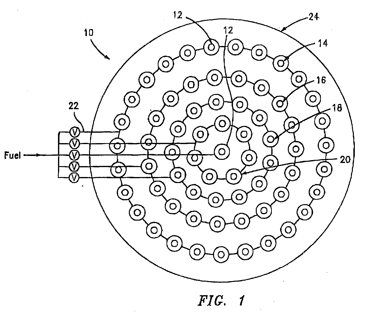
- FIG. 1 illustrates a first embodiment of a multipoint injector 10 in accordance with the present invention.
- the multi-point injector 10 has nozzles 12 for injecting a fuel-air mixture into a combustor stage of a gas turbine engine.
- the nozzles 12 are arranged in a plurality of arrays.
- the nozzles 12 are arranged in four concentric rings 14, 16, 18, and 20 with an optional nozzle in the center. While the nozzle arrays have been shown to be concentric rings, it should be recognized that the nozzles 12 can be arranged in different configurations, including but not limited to squares, rectangles, hexagons, or parallel lines.
- the fuel flow rate controlling means comprises a different fuel circuit 22 for each ring 14, 16, 18, and 20 and the optional center nozzle.
- Each fuel circuit 22 may each comprise any suitable valve and conduit arrangement known in the art for allowing control over the flow rate of the fuel provided to each one of the rings 14, 16, 18 and 20 and to the optional center nozzle.
- the flow of fuel is reduced differently for each ring 14, 16, 18 and 20 and the optional center nozzle.
- the outermost ring 14 may be kept at a flame temperature that is high enough to keep the flame stable so that CO and UHC created from the combustor and dynamic pressure is low, but not so high that ring 14 creates excessive NOx.
- the other rings 16, 18, and 20 and the optional center nozzle are preferably fueled at lower fuel/air ratios. As a result, lower flame temperature occurs at these rings to achieve more power reduction or to accommodate lower ambient temperature.
- some or all of the other rings can be fueled at higher fuel/air ratios if better flame stability is wanted and if NOx limit and power setting/ambient temperature allow. Since nozzle rings 16, 18, and 20 do not interact with the cooler wall or cooling film on the combustor wall 24, the flame from the nozzles 12 in those rings will be less quenched, thus avoiding the creating of excessive CO and UHC. In this way, the CO and UHC emissions can be reduced at lower power settings of the engine or at lower ambient temperature. Since the nozzles 12 in ring 14 are kept at a high enough flame temperature as the power is reduced or ambient temperature is reduced, they can serve as flame stabilizers to stabilize the entire combustion process for all the nozzles 12 and extend lean blowout limit.
- each ring 14, 16, 18, and 20 may define a zone and the injector may be provided with a means for controlling the flow of fuel to one zone as a function of the flow of fuel to a second zone.
- the injector 10 and the method outlined above can be used in different kind of combustors (can or annular).
- annular burneras shown in Figure 5 the flame temperatures in the zones near at least one of the combustor walls 24 is kept high enough to stablize the flame while leaning some others to reduce power or to accommodate lower ambient temperature.
- the annular burner will have a plurality of nozzle rings such as nozzle rings 16, 18 and 20.
- the zone which is kept hot to stabilize the flame preferably is the one next to a wall. In some instances, this may be the outermost ring of nozzles. In other instances, this may be the innermost ring of nozzles. In some situations, it may be desirable to keep an outer zone hot, a middle zone cool, and an inner zone hot.
- FIG. 1 illustrates the use of four rings 14, 16, 18, and 20, the number of rings of nozzles can be arbitrary. Different rings of nozzles can be fueled differently to achieve the best emissions and stability.
- FIGS. 2 and 3 illustrate an embodiment of an injector 10' which has three concentric rings 30, 32, and 34 of nozzles 12. The rings of nozzles 30, 32, and 34 may be fueled so that the outermost ring 30 and the innermost ring 34 are maintained hotter than the center ring 32. As before, each of the rings 30, 32, and 34 of nozzles 12 may be fueled via independent fuel circuits 22A, 22B, and 22C, respectively.
- the centerbody portion 36 may be closed if desired or used to inject fuel or fuel/air mixture and an ignitor 38 may be positioned off center.
- each nozzle 12 used in the embodiments of FIGS. 1 and 2 may have a construction such as that shown in FIG. 4.
- each nozzle 12 may have an outer body 40, such as a cylindrical or other shape casing, an inner body 42 which is cylindrical, conical, rectangular and the like, centered or off-centered or even non-existent and one or more swirler vanes 44 extending between the inner body 42 and an inner wall 46 of the casing 40.
- the swirler vanes 44 are used to create a swirling flow in the fluid channel 47 formed by the inner wall of the outer body 40 and the inner body 42. It has been found that the creation of the swirlingflow in the channel 47 promotes mixing of the fuel and air which reduces NOx and flame stabilization.
- the swirler vanes 44 for a respective nozzle 12 may be in the same direction or in different directions.
- Each nozzle 12 used in the embodiments of FIGS. 1 and 2 may have otherconstructions such as that shown in FIG. 6.
- the fuel and air aretangentially injected from the outer wall of a swirl cup 58 via tangential inlets 60 and 62 respectively to create swirling motion.
- the injection direction does not have to be perpendicular to the axis of the swirl cup 58.
- One or more fuel inlets can be injecting fuel upstream or downstream of the air injection or injections, or in between air injections. Axial air or fuel or both can also be added.
- vanes 44 may be omitted if desired.
- each nozzle 12 is provided with a fuel/air mixture.
- a fuel injection unit 49 may be placed adjacent the inlet 51 of the nozzle 12 for premixed flame or be placed adjacent to outlet 52 for diffusion flame.
- the fuel injection unit 49 may have one or more fuel inlets 50 for delivering fuel to the interior of the fuel injection unit 49.
- the fuel injection unit can also be an object hanging in the air stream.
- the fuel inlet 50 can be upstream or downstream of the vanes 44, in the area of the vanes 44, in the vanes 44, from the wall of the outer body 40, or from the inner body 42
- the fuel inlets 50 may be supplied with fuel from one of the fuel circuits 22A, 22B, and 22C. While the fuel injection unit 49 and nozzle 12 may be separate elements, they could also be a single integral unit. Further, a diffusion or premixed pilot can be added to the inner body 42.
- the swirl vane angle does not have to be the same within the swirler, within the zone, or among different zones. Further, the outlet of all the nozzles does not have to be in one plane.
- Liquid fuel can be prevaporized or directly injected into the nozzle 12.
- the liquid fuel can be injected from the inner body 42, outer body 40, vanes, or from a separate injection unit or injection units.
- the liquid fuel can be injected from the bottom of the swirl cup 58, the outer wall, the inlets 60, 62, or from a separate injection unit or injection units.
- the nozzles 12 in each of the arrays in the embodiments of FIGS. 1 and 2 have outlets 52 which terminate in a common plane 54, although this is not mandatory. It has been found that by providing such a non-staggered nozzle arrargement, the nozzles 12 in one array, due to the arrangement and the turbulent flow exiting the nozzle 12, can aid combustion of the fuel/air mixture in the nozzles 12 of an adjacent array or within the array. This is highly desirable from the standpoint of promoting flame stability. Such assistance is less effective in arrangements where the nozzle outlets are staggered although it is still possible.
- injectors 10 of the present invention it is possible to achieve the production of low quantities of NOx, CO and UHC for extended power range and ambient conditions.
- NOx at a level of less than 7.0 ppm and to have both CO and UHC at levels less than 10 ppm for extended poweror ambient range.
- the injectors of the present invention don't turn fuel off to a particular array or ring. Fuel is always fed to each nozzle in each array or ring. Thus, in the injectors of the present invention, one does not have to worry about a disabled zone quenching an enabled zone. As a result, one does not have to have annular baffles and/or axial separation. In the injectors of the present invention, the various arrays or rings of nozzles 12 are designed to interact with each other.
- FIG. 7 illustrates a parallel array burner having five fuel zones 70, 72, 74, 76, 78 with each fuel zone being independently controlled for staging the flame temperature in at least one zone, preferably the zone near the burner wall 24, is kept high enough to stabilize the entire flame.
Landscapes
- Engineering & Computer Science (AREA)
- Chemical & Material Sciences (AREA)
- Combustion & Propulsion (AREA)
- Mechanical Engineering (AREA)
- General Engineering & Computer Science (AREA)
Abstract
Description
- The present invention relates to a multi-point fuel injector for use in a combustor of a gas turbine engine or other types of combustors
- One of the biggest challenges for gas turbines, especially for industrial applications, is to have good emission performance and combustion stability for a wide range of power settings and ambient condition. If one has an industrial gas turbine with low emissions of NOx, CO and UHC at 100% power, as one reduces the power, which is usually done by reducing the amount of fuel to the engine, the fuel/air mixture in the combustor typically gets leaner. The leaner mixture of fuel/air lowers the flame temperature and creates a flame which can be quenched relatively easily by a cooler combustor wall or cooling film on the combustor wall. The quenchingeffect creates excessive CO and UHC and high dynamic pressure If they are not further oxidized, the CO and UHC become pollutants. The other issue associated with too lean fuel/air mixture is that it creates unstable combustion. Conversely, if one has a gas turbine with low NOx, CO, UHC and acoustics at part power condition, as one increases the power, which is usually done by increasing the amount of fuel to the engine, the fuel/air mixture in the combustor typically gets richer. The richer mixture of fuel/air raises the flame temperature and creates a flame which can generate more NOx. Similar situations can happen with different ambient temperatures. If one has a gas turbine with low NOx, CO, UHC and acoustics at high ambient temperature, as ambient temperature becomes lower, the flame temperature decreases which may create high CO, UHC and unstable flame. Or if one has a gas turbine withlow NOx, CO, UHC and acoustics at low ambient temperature, as ambient temperature becomes higher, the flame temperature increases which may create excessive NOx.
- Accordingly, it is an object of the present invention to provide a multi-point fuel injector which addresses emission and stability problems.
- It is a further object of the present invention to provide an improved method for injecting a fuel/air mixture into a combustor of a turbine engine or other applications which avoids creating excessive CO and UHC at wide power levels and ambient conditions.
- The foregoing objects are attained by the present invention.
- In accordance with one aspect of the present invention, a novel multi-point injector is provided. The multi-point injector broadly comprises a plurality of nozzles arranged in at least two arrays and means for independently controlling a fuel flow to each array of nozzles. Each of the nozzles in each array includes an outer body defining a fluid channel and vane means for creating a swirling flow within the fluid channel.
- Further, in accordance with another aspect of the present invention, a method for injecting a fuel/air mixture into a combustor of a gas turbine engine is provided. The method broadly comprises the steps of providing an injector having nozzles arranged in at least two arrays, injecting a fuel/air mixture into the combustor stage by supplying fuel in a first quantity to each nozzle in an outermost one of the arrays and supplying fuel in a second quantity to each nozzle in a second one of the arrays; and maintaining the outermost one of the arrays at a flame temperature high enough to maintain a stable and less polluting flame.
- Other details of the multi-point staging strategy for low emissions and stable combustion of the present invention are set forth in the following detailed description and the accompanying drawings wherein like reference numerals depict like elements.
-
- FIG. 1 illustrates a first embodiment of a multi-point injector in accordance with the present invention;
- FIG. 2 illustrates a second embodiment of a multi-point injector in accordance with the present invention;
- FIG. 3 is a sectional view taken along lines 3 - 3 in FIG. 2;
- FIG. 4 is an enlarged view of a nozzle used in the multi-point injectors of the present invention;
- FIG. 5 illustrates an annular burner having an injector in accordance with the present invention;
- FIG. 6 illustrates a tangential entry swirl device which can be used in the injector of the present invention; and
- FIG. 7 illustrates a parallel array burner having five fuel zones.
-
- Referring now to the drawings, FIG. 1 illustrates a first embodiment of a
multipoint injector 10 in accordance with the present invention. Themulti-point injector 10 hasnozzles 12 for injecting a fuel-air mixture into a combustor stage of a gas turbine engine. Thenozzles 12 are arranged in a plurality of arrays. In the embodiment of FIG. 1, thenozzles 12 are arranged in fourconcentric rings nozzles 12 can be arranged in different configurations, including but not limited to squares, rectangles, hexagons, or parallel lines. - In accordance with the present invention, means for independently controlling the fuel flow rate for each of the
rings different fuel circuit 22 for eachring fuel circuit 22 may each comprise any suitable valve and conduit arrangement known in the art for allowing control over the flow rate of the fuel provided to each one of therings - When power reduction is required or ambient temperature is reduced, instead of reducing fuel to all
nozzles 12 to the same extent, the flow of fuel is reduced differently for eachring outermost ring 14 may be kept at a flame temperature that is high enough to keep the flame stable so that CO and UHC created from the combustor and dynamic pressure is low, but not so high thatring 14 creates excessive NOx. Theother rings combustor wall 24, the flame from thenozzles 12 in those rings will be less quenched, thus avoiding the creating of excessive CO and UHC. In this way, the CO and UHC emissions can be reduced at lower power settings of the engine or at lower ambient temperature. Since thenozzles 12 inring 14 are kept at a high enough flame temperature as the power is reduced or ambient temperature is reduced, they can serve as flame stabilizers to stabilize the entire combustion process for all thenozzles 12 and extend lean blowout limit. - If desired, each
ring - The
injector 10 and the method outlined above can be used in different kind of combustors (can or annular). In an annular burneras shown in Figure 5, the flame temperatures in the zones near at least one of thecombustor walls 24 is kept high enough to stablize the flame while leaning some others to reduce power or to accommodate lower ambient temperature. Typically, the annular burner will have a plurality of nozzle rings such asnozzle rings - While FIG. 1 illustrates the use of four
rings concentric rings nozzles 12. The rings ofnozzles outermost ring 30 and theinnermost ring 34 are maintained hotter than thecenter ring 32. As before, each of therings nozzles 12 may be fueled viaindependent fuel circuits - In the injector embodiments of the present invention, the
centerbody portion 36 may be closed if desired or used to inject fuel or fuel/air mixture and anignitor 38 may be positioned off center. - Each
nozzle 12 used in the embodiments of FIGS. 1 and 2 may have a construction such as that shown in FIG. 4. In particular, eachnozzle 12 may have anouter body 40, such as a cylindrical or other shape casing, aninner body 42 which is cylindrical, conical, rectangular and the like, centered or off-centered or even non-existent and one ormore swirler vanes 44 extending between theinner body 42 and aninner wall 46 of thecasing 40. Theswirler vanes 44 are used to create a swirling flow in thefluid channel 47 formed by the inner wall of theouter body 40 and theinner body 42. It has been found that the creation of the swirlingflow in thechannel 47 promotes mixing of the fuel and air which reduces NOx and flame stabilization. The swirler vanes 44 for arespective nozzle 12 may be in the same direction or in different directions. - Each
nozzle 12 used in the embodiments of FIGS. 1 and 2 may have otherconstructions such as that shown in FIG. 6. In the embodiment of FIG. 6, the fuel and air aretangentially injected from the outer wall of aswirl cup 58 viatangential inlets swirl cup 58. One or more fuel inlets can be injecting fuel upstream or downstream of the air injection or injections, or in between air injections. Axial air or fuel or both can also be added. - While swirling may be used in each
nozzle 12, the present invention will work without swirling and thus vanes 44 may be omitted if desired. - Further, each
nozzle 12 is provided with a fuel/air mixture. If desired, afuel injection unit 49 may be placed adjacent theinlet 51 of thenozzle 12 for premixed flame or be placed adjacent tooutlet 52 for diffusion flame. Thefuel injection unit 49 may have one ormore fuel inlets 50 for delivering fuel to the interior of thefuel injection unit 49. The fuel injection unit can also be an object hanging in the air stream. Thefuel inlet 50 can be upstream or downstream of thevanes 44, in the area of thevanes 44, in thevanes 44, from the wall of theouter body 40, or from theinner body 42 The fuel inlets 50 may be supplied with fuel from one of thefuel circuits fuel injection unit 49 andnozzle 12 may be separate elements, they could also be a single integral unit. Further, a diffusion or premixed pilot can be added to theinner body 42. - It should be noted that in an axial swirler design, the swirl vane angle does not have to be the same within the swirler, within the zone, or among different zones. Further, the outlet of all the nozzles does not have to be in one plane.
- Also, in the hot zone near the
wall 24, some swirlers can be kept cool, while others are kept hot, as long as the entire flame is stable. - Liquid fuel can be prevaporized or directly injected into the
nozzle 12. For the direct injection of liquid fuel, in the axial swirler design of FIG. 4, the liquid fuel can be injected from theinner body 42,outer body 40, vanes, or from a separate injection unit or injection units. In a tangential entry design shown in FIG. 6, the liquid fuel can be injected from the bottom of theswirl cup 58, the outer wall, theinlets - It is also preferred that the
nozzles 12 in each of the arrays in the embodiments of FIGS. 1 and 2 haveoutlets 52 which terminate in acommon plane 54, although this is not mandatory. It has been found that by providing such a non-staggered nozzle arrargement, thenozzles 12 in one array, due to the arrangement and the turbulent flow exiting thenozzle 12, can aid combustion of the fuel/air mixture in thenozzles 12 of an adjacent array or within the array. This is highly desirable from the standpoint of promoting flame stability. Such assistance is less effective in arrangements where the nozzle outlets are staggered although it is still possible. - Using the
injectors 10 of the present invention, it is possible to achieve the production of low quantities of NOx, CO and UHC for extended power range and ambient conditions. For example, using the injector 10' of FIG. 2, it is possible to have NOx at a level of less than 7.0 ppm and to have both CO and UHC at levels less than 10 ppm for extended poweror ambient range. - The injectors of the present invention don't turn fuel off to a particular array or ring. Fuel is always fed to each nozzle in each array or ring. Thus, in the injectors of the present invention, one does not have to worry about a disabled zone quenching an enabled zone. As a result, one does not have to have annular baffles and/or axial separation. In the injectors of the present invention, the various arrays or rings of
nozzles 12 are designed to interact with each other. - FIG. 7 illustrates a parallel array burner having five
fuel zones burner wall 24, is kept high enough to stabilize the entire flame. - It is apparent that there has been provided in accordance with the present invention a multi-point staging for low emissions and stable combustion which fully satisfies the objects, means, and advantages set forth hereinbefore. While the present invention has been described in the context of specific embodiments thereof, other alternatives, modifications, and variations will become apparent to those skilled in the art having read the foregoing description. Accordingly, it is intended to embrace those alternatives, modifications, and variations as fall within the broad scope of the appended claims.
Claims (21)
- A multi-point fuel injector for use in a combustor stage of a gas turbine engine comprising:a plurality of nozzles (12) arranged in at least two arrays (14, 16, 18, 20; 30, 32, 34; 70, 72, 74, 76);means (22) for independently controlling a flow of fuel to the nozzles in each of said arrays; andeach of said nozzles including a fluid channel (47) and means (44; 60, 62) for creating a swirling flow within the fluid channel.
- A multi-point fuel injector according to claim 1, wherein said swirling flow creating means comprises vane means (44) or angled injectors (60, 22).
- A multi-point fuel injector according to claim 1 or 2, wherein said independent fuel flow controlling means comprises a different fuel circuit (22A, 22B, 22C) for the nozzles in each of said arrays.
- A multi-point fuel injector according to claim 1, 2 or 3, wherein said arrays comprise at least two concentric rings (14, 16, 18, 20; 30, 32, 34).
- A multi-point fuel injector according to any preceding claim, wherein said swirling flow creation means comprises a plurality of swirler vanes (44) within the fluid channel.
- A multi-point fuel injector according to claim 5, wherein said arrays includes an outer ring (14; 30) of nozzles and at least one inner ring (20; 34) of nozzles and wherein each swirler vane (44) in each said nozzle in said outer ring has a swirl angle different from a swirl angle for each swirler vane in each said nozzle in each said inner ring.
- A multi-point fuel injector according to claim 6, wherein said swirl angle for each said swirler vane (44) in said outer ring (14; 30) is less than said swirl vane angle for each said swirler vane (44) in each said inner ring (20; 34).
- A multi-point fuel injector according to claim 6, wherein said outer ring (14; 30) is kept at a flame temperature high enough so that the outer ring creates low CO and UHC but not so high that excessive NOx is created.
- A multi-point fuel injector according to claim 6, wherein said nozzles in said at least one inner ring (20; 34) are fueled at a fuel/air ratio lower than a fuel/air ratio at which the outer ring (14; 30) is fueled to achieve power reduction or to accommodate lower ambient temperature.
- A multi-point fuel injector according to any preceding claim, wherein each said nozzle (12) in each said array has an outlet (52) and wherein said nozzle outlets terminate in a common plane (54) to promote flame stability and interaction between said nozzles in adjacent ones of said arrays.
- A multi-point fuel injector according to any preceding claim, further comprising a mixer associated with each said nozzle for providing a fuel and air mixture to each said nozzle.
- A multi-point fuel injector for use in a combustor stage of a gas turbine engine comprising:a plurality of nozzles (12) arranged in at least two arrays (14, 16, 18, 20; 30, 32, 34; 70, 72, 74, 76);each of said nozzles in each of said arrays having an inlet (51) and an outlet (52);said nozzle outlets (52) in each of said arrays being arranged in a common plane (54) to promote flame stability and interaction between the nozzles in adjacent arrays; andmeans (22) for independently controlling a flow of fuel and air to the nozzles in each said array.
- A multi-point fuel injector according to claim 12, further comprising means within each said nozzle (12) for creating a turbulent flow to mix said fuel and air and wherein said turbulent flow creating means comprises a plurality of swirler vanes (44).
- A multi-point fuel injector according to claim 12 or 13, wherein said independent fuel and air controlling means (22) comprises means for providing the nozzles (12) in an outermost (14; 30) one of said arrays with a first fuel/air ratio and for providing thenozzles (12) in an inner (20; 34) one of said arrays with a second fuel/air ratio and said firstfuel/air ratio being high enough to stablize the entire flame.
- A multi-point fuel injector according to claim 12 or 13, wherein said nozzles in an outermost one (14; 30) of said arrays is kept at first flame temperature and said nozzles in an inner one (20; 34) of said arrays is kept as a second flame temperature and the first flame temperature is kept high enough to stablize the entire flame.
- A multi-point fuel injector according to any of claims 12 to 15, wherein each of said arrays defines a zone and said injector further comprises means for controlling a flow to a first zone as a function of flow to a second zone.
- A method for injecting a fuel/air mixture into a combustor stage of a gas turbine engine comprising the steps of:providing an injector having nozzles (12) arranged in multiple arrays (14, 16, 18, 20; 30, 32, 34; 70, 72, 74, 76);injecting a fuel/air mixture into said combustor stage by supplying fuel to each said nozzle in each of said arrays via independent flow circuits (22) so that the nozzles in a first of said arrays receive fuel from a first flow circuit and nozzles in a second one of said arrays receive fuel from a second flow circuit; andmaintaining said nozzles in an outermost one (14; 30) of said arrays at a flame temperature high enough to maintain a stable and less polluting flame.
- A method according to claim 17, further comprising mixing air with said fuel supplied to each said nozzle (12) and creating a turbulent flow within each of said nozzles (12) to enhance mixing of said air and fuel and wherein said turbulent flow creating step comprises providing a plurality of swirler vanes (44) in each of said nozzles (12) and passing said fuel/air mixture through passageways between adjacent ones of said swirler vanes.
- A method according to claim 17 or 18, wherein said injecting step comprises always providing each of said nozzles (12) with a flow of fuel.
- A method according to any of claims 17 to 19, further comprising arranging said nozzles (12) in each of said arrays so that outlets (52) of said nozzles lie in a common plane (54) to enhance flame stability and interaction between said nozzles in adjacent ones of said arrays.
- A method according to any of claims 17 to 20, wherein said providing step comprises providing a multi-point injector having nozzles arranged in three rings (30, 32, 34) and said maintaining step comprises maintaining an outermost one (30) of said rings at a first flame temperature, maintaining a central (32) one of said rings at a second flame temperature lower than said first flame temperature, and maintaining an inner one (34) of said rings at a third flame temperature higher than at least one of the second and firstflame temperatures.
Priority Applications (1)
| Application Number | Priority Date | Filing Date | Title |
|---|---|---|---|
| EP03257138A EP1531305A1 (en) | 2003-11-12 | 2003-11-12 | Multi-point fuel injector |
Applications Claiming Priority (1)
| Application Number | Priority Date | Filing Date | Title |
|---|---|---|---|
| EP03257138A EP1531305A1 (en) | 2003-11-12 | 2003-11-12 | Multi-point fuel injector |
Publications (1)
| Publication Number | Publication Date |
|---|---|
| EP1531305A1 true EP1531305A1 (en) | 2005-05-18 |
Family
ID=34429530
Family Applications (1)
| Application Number | Title | Priority Date | Filing Date |
|---|---|---|---|
| EP03257138A Withdrawn EP1531305A1 (en) | 2003-11-12 | 2003-11-12 | Multi-point fuel injector |
Country Status (1)
| Country | Link |
|---|---|
| EP (1) | EP1531305A1 (en) |
Cited By (7)
| Publication number | Priority date | Publication date | Assignee | Title |
|---|---|---|---|---|
| US7673454B2 (en) | 2006-03-30 | 2010-03-09 | Mitsubishi Heavy Industries, Ltd. | Combustor of gas turbine and combustion control method for gas turbine |
| WO2010112318A1 (en) * | 2009-04-01 | 2010-10-07 | Alstom Technology Ltd. | Gas turbine exhibiting improved partial load emission behavior |
| CN102052158A (en) * | 2009-11-09 | 2011-05-11 | 通用电气公司 | Counter rotated gas turbine fuel nozzles |
| RU2566621C2 (en) * | 2012-10-22 | 2015-10-27 | Альстом Текнолоджи Лтд | Method of operation of gas turbine with successive combustion and gas turbine for this method implementation |
| WO2018212761A1 (en) * | 2017-05-16 | 2018-11-22 | Siemens Aktiengesellschaft | Binary fuel staging scheme for improved turndown emissions in lean premixed gas turbine combustion |
| CN118328419A (en) * | 2024-06-04 | 2024-07-12 | 江苏科技大学 | A vortex control stabilizer |
| US12276423B2 (en) | 2021-09-23 | 2025-04-15 | General Electric Company | Floating primary vane swirler |
Citations (10)
| Publication number | Priority date | Publication date | Assignee | Title |
|---|---|---|---|---|
| US3943705A (en) * | 1974-11-15 | 1976-03-16 | Westinghouse Electric Corporation | Wide range catalytic combustor |
| US4356698A (en) * | 1980-10-02 | 1982-11-02 | United Technologies Corporation | Staged combustor having aerodynamically separated combustion zones |
| EP0335978A1 (en) * | 1987-09-04 | 1989-10-11 | Hitachi, Ltd. | Gas turbine combustor |
| US5303542A (en) * | 1992-11-16 | 1994-04-19 | General Electric Company | Fuel supply control method for a gas turbine engine |
| EP0620402A1 (en) * | 1993-04-15 | 1994-10-19 | Westinghouse Electric Corporation | Premix combustor with concentric annular passages |
| DE4412315A1 (en) * | 1994-04-11 | 1995-10-12 | Abb Management Ag | Method of operating gas turbine combustion chamber |
| US5469700A (en) * | 1991-10-29 | 1995-11-28 | Rolls-Royce Plc | Turbine engine control system |
| EP0974789A1 (en) * | 1998-07-22 | 2000-01-26 | Asea Brown Boveri AG | Method of operating the combustion chamber of a liquid-fuel gas turbine |
| US6092363A (en) * | 1998-06-19 | 2000-07-25 | Siemens Westinghouse Power Corporation | Low Nox combustor having dual fuel injection system |
| US6360525B1 (en) * | 1996-11-08 | 2002-03-26 | Alstom Gas Turbines Ltd. | Combustor arrangement |
-
2003
- 2003-11-12 EP EP03257138A patent/EP1531305A1/en not_active Withdrawn
Patent Citations (10)
| Publication number | Priority date | Publication date | Assignee | Title |
|---|---|---|---|---|
| US3943705A (en) * | 1974-11-15 | 1976-03-16 | Westinghouse Electric Corporation | Wide range catalytic combustor |
| US4356698A (en) * | 1980-10-02 | 1982-11-02 | United Technologies Corporation | Staged combustor having aerodynamically separated combustion zones |
| EP0335978A1 (en) * | 1987-09-04 | 1989-10-11 | Hitachi, Ltd. | Gas turbine combustor |
| US5469700A (en) * | 1991-10-29 | 1995-11-28 | Rolls-Royce Plc | Turbine engine control system |
| US5303542A (en) * | 1992-11-16 | 1994-04-19 | General Electric Company | Fuel supply control method for a gas turbine engine |
| EP0620402A1 (en) * | 1993-04-15 | 1994-10-19 | Westinghouse Electric Corporation | Premix combustor with concentric annular passages |
| DE4412315A1 (en) * | 1994-04-11 | 1995-10-12 | Abb Management Ag | Method of operating gas turbine combustion chamber |
| US6360525B1 (en) * | 1996-11-08 | 2002-03-26 | Alstom Gas Turbines Ltd. | Combustor arrangement |
| US6092363A (en) * | 1998-06-19 | 2000-07-25 | Siemens Westinghouse Power Corporation | Low Nox combustor having dual fuel injection system |
| EP0974789A1 (en) * | 1998-07-22 | 2000-01-26 | Asea Brown Boveri AG | Method of operating the combustion chamber of a liquid-fuel gas turbine |
Cited By (15)
| Publication number | Priority date | Publication date | Assignee | Title |
|---|---|---|---|---|
| DE102007004864C5 (en) * | 2006-03-30 | 2014-09-25 | Mitsubishi Heavy Industries, Ltd. | Combustion chamber of a gas turbine and combustion control method for a gas turbine |
| DE102007004864B4 (en) * | 2006-03-30 | 2010-08-19 | Mitsubishi Heavy Industries, Ltd. | Combustion chamber of a gas turbine and combustion control method for a gas turbine |
| US7673454B2 (en) | 2006-03-30 | 2010-03-09 | Mitsubishi Heavy Industries, Ltd. | Combustor of gas turbine and combustion control method for gas turbine |
| WO2010112318A1 (en) * | 2009-04-01 | 2010-10-07 | Alstom Technology Ltd. | Gas turbine exhibiting improved partial load emission behavior |
| US8434312B2 (en) | 2009-04-01 | 2013-05-07 | Alstom Technology Ltd. | Gas turbine with improved part load emissions behavior |
| US8794008B2 (en) | 2009-04-01 | 2014-08-05 | Alstom Technology Ltd | Methods of operation of a gas turbine with improved part load emissions behavior |
| CN102052158A (en) * | 2009-11-09 | 2011-05-11 | 通用电气公司 | Counter rotated gas turbine fuel nozzles |
| RU2566621C2 (en) * | 2012-10-22 | 2015-10-27 | Альстом Текнолоджи Лтд | Method of operation of gas turbine with successive combustion and gas turbine for this method implementation |
| US9518511B2 (en) | 2012-10-22 | 2016-12-13 | General Electric Technology Gmbh | Method for operating a gas turbine with sequential combustion and gas turbine for conducting said method |
| WO2018212761A1 (en) * | 2017-05-16 | 2018-11-22 | Siemens Aktiengesellschaft | Binary fuel staging scheme for improved turndown emissions in lean premixed gas turbine combustion |
| CN110612419A (en) * | 2017-05-16 | 2019-12-24 | 西门子公司 | Improvement of Lean Premixed Gas Turbine Combustion with a Binary Fuel Staging Scheme for Lower Emissions |
| US11125437B2 (en) | 2017-05-16 | 2021-09-21 | Siemens Energy Global GmbH & Co. KG | Binary fuel staging scheme for improved turndown emissions in lean premixed gas turbine combustion |
| CN110612419B (en) * | 2017-05-16 | 2022-01-25 | 西门子能源全球两合公司 | Improved emission-turndown binary fuel staging scheme for lean premixed gas turbine combustion |
| US12276423B2 (en) | 2021-09-23 | 2025-04-15 | General Electric Company | Floating primary vane swirler |
| CN118328419A (en) * | 2024-06-04 | 2024-07-12 | 江苏科技大学 | A vortex control stabilizer |
Similar Documents
| Publication | Publication Date | Title |
|---|---|---|
| US6962055B2 (en) | Multi-point staging strategy for low emission and stable combustion | |
| US5511375A (en) | Dual fuel mixer for gas turbine combustor | |
| US6092363A (en) | Low Nox combustor having dual fuel injection system | |
| US5640851A (en) | Gas turbine engine combustion chamber | |
| US5899075A (en) | Turbine engine combustor with fuel-air mixer | |
| JP4205231B2 (en) | Burner | |
| US5590529A (en) | Air fuel mixer for gas turbine combustor | |
| US5351477A (en) | Dual fuel mixer for gas turbine combustor | |
| US5435126A (en) | Fuel nozzle for a turbine having dual capability for diffusion and premix combustion and methods of operation | |
| EP1407195B1 (en) | Premixing chamber for turbine combustor | |
| US6993916B2 (en) | Burner tube and method for mixing air and gas in a gas turbine engine | |
| EP1193448B1 (en) | Multiple annular combustion chamber swirler having atomizing pilot | |
| CN101294714B (en) | Combustor and a fuel supply method for the combustor | |
| US5899074A (en) | Gas turbine combustor and operation method thereof for a diffussion burner and surrounding premixing burners separated by a partition | |
| US6722132B2 (en) | Fully premixed secondary fuel nozzle with improved stability and dual fuel capability | |
| US5295352A (en) | Dual fuel injector with premixing capability for low emissions combustion | |
| US20090056336A1 (en) | Gas turbine premixer with radially staged flow passages and method for mixing air and gas in a gas turbine | |
| US8499564B2 (en) | Pilot burner for gas turbine engine | |
| US20040006993A1 (en) | Dual fuel fin mixer secondary fuel nozzle | |
| EP0927854A2 (en) | Low nox combustor for gas turbine engine | |
| US20100319353A1 (en) | Multiple Fuel Circuits for Syngas/NG DLN in a Premixed Nozzle | |
| US20100192583A1 (en) | Non-rotational stabilization of the flame of a premixing burner | |
| CN101644435A (en) | Lean direct injection diffusion tip and related method | |
| EP4056902B1 (en) | Fuel mixer | |
| JP2021175925A (en) | Gas turbine combustor |
Legal Events
| Date | Code | Title | Description |
|---|---|---|---|
| PUAI | Public reference made under article 153(3) epc to a published international application that has entered the european phase |
Free format text: ORIGINAL CODE: 0009012 |
|
| AK | Designated contracting states |
Kind code of ref document: A1 Designated state(s): AT BE BG CH CY CZ DE DK EE ES FI FR GB GR HU IE IT LI LU MC NL PT RO SE SI SK TR |
|
| AX | Request for extension of the european patent |
Extension state: AL LT LV MK |
|
| 17P | Request for examination filed |
Effective date: 20051102 |
|
| AKX | Designation fees paid |
Designated state(s): DE FR GB |
|
| 17Q | First examination report despatched |
Effective date: 20070131 |
|
| RAP1 | Party data changed (applicant data changed or rights of an application transferred) |
Owner name: UNITED TECHNOLOGIES CORPORATION |
|
| GRAP | Despatch of communication of intention to grant a patent |
Free format text: ORIGINAL CODE: EPIDOSNIGR1 |
|
| STAA | Information on the status of an ep patent application or granted ep patent |
Free format text: STATUS: GRANT OF PATENT IS INTENDED |
|
| INTG | Intention to grant announced |
Effective date: 20171027 |
|
| STAA | Information on the status of an ep patent application or granted ep patent |
Free format text: STATUS: THE APPLICATION IS DEEMED TO BE WITHDRAWN |
|
| 18D | Application deemed to be withdrawn |
Effective date: 20180307 |