EP1531265A2 - Heat-insulating mechanism for compressor - Google Patents
Heat-insulating mechanism for compressor Download PDFInfo
- Publication number
- EP1531265A2 EP1531265A2 EP04027216A EP04027216A EP1531265A2 EP 1531265 A2 EP1531265 A2 EP 1531265A2 EP 04027216 A EP04027216 A EP 04027216A EP 04027216 A EP04027216 A EP 04027216A EP 1531265 A2 EP1531265 A2 EP 1531265A2
- Authority
- EP
- European Patent Office
- Prior art keywords
- passage
- heat
- communication
- pressure region
- insulating
- Prior art date
- Legal status (The legal status is an assumption and is not a legal conclusion. Google has not performed a legal analysis and makes no representation as to the accuracy of the status listed.)
- Withdrawn
Links
- 239000003507 refrigerant Substances 0.000 claims abstract description 76
- 230000006835 compression Effects 0.000 claims abstract description 26
- 238000007906 compression Methods 0.000 claims abstract description 26
- 239000011810 insulating material Substances 0.000 claims abstract description 8
- 230000002093 peripheral effect Effects 0.000 claims description 44
- CURLTUGMZLYLDI-UHFFFAOYSA-N Carbon dioxide Chemical compound O=C=O CURLTUGMZLYLDI-UHFFFAOYSA-N 0.000 claims description 10
- 229910002092 carbon dioxide Inorganic materials 0.000 claims description 5
- 239000001569 carbon dioxide Substances 0.000 claims description 5
- 238000011144 upstream manufacturing Methods 0.000 claims description 2
- 238000006073 displacement reaction Methods 0.000 description 10
- 230000007423 decrease Effects 0.000 description 9
- 238000005192 partition Methods 0.000 description 5
- XAGFODPZIPBFFR-UHFFFAOYSA-N aluminium Chemical compound [Al] XAGFODPZIPBFFR-UHFFFAOYSA-N 0.000 description 4
- 229910052782 aluminium Inorganic materials 0.000 description 4
- 230000001105 regulatory effect Effects 0.000 description 3
- 229920003002 synthetic resin Polymers 0.000 description 3
- 239000000057 synthetic resin Substances 0.000 description 3
- 229920001875 Ebonite Polymers 0.000 description 2
- 238000003780 insertion Methods 0.000 description 2
- 230000037431 insertion Effects 0.000 description 2
- KYKAJFCTULSVSH-UHFFFAOYSA-N chloro(fluoro)methane Chemical compound F[C]Cl KYKAJFCTULSVSH-UHFFFAOYSA-N 0.000 description 1
- 230000001276 controlling effect Effects 0.000 description 1
- 230000008878 coupling Effects 0.000 description 1
- 238000010168 coupling process Methods 0.000 description 1
- 238000005859 coupling reaction Methods 0.000 description 1
- 238000007599 discharging Methods 0.000 description 1
- 230000000694 effects Effects 0.000 description 1
- 230000002708 enhancing effect Effects 0.000 description 1
- 238000003754 machining Methods 0.000 description 1
- 230000002265 prevention Effects 0.000 description 1
Images

Classifications
-
- F—MECHANICAL ENGINEERING; LIGHTING; HEATING; WEAPONS; BLASTING
- F04—POSITIVE - DISPLACEMENT MACHINES FOR LIQUIDS; PUMPS FOR LIQUIDS OR ELASTIC FLUIDS
- F04B—POSITIVE-DISPLACEMENT MACHINES FOR LIQUIDS; PUMPS
- F04B39/00—Component parts, details, or accessories, of pumps or pumping systems specially adapted for elastic fluids, not otherwise provided for in, or of interest apart from, groups F04B25/00 - F04B37/00
- F04B39/06—Cooling; Heating; Prevention of freezing
Definitions
- the present invention relates to a heat-insulating mechanism for a compressor which introduces refrigerant gas from a suction pressure region into a compression chamber and discharges the refrigerant gas from the compression chamber to a discharge pressure region.
- the temperature of refrigerant gas introduced from the outside of a compressor into a suction pressure region of the compressor influences the performance of the compressor.
- the density of the refrigerant gas to be introduced into a compression chamber reduces, with the consequence of deteriorated performance of the compressor.
- a rear cover forms therein a suction passage for introducing refrigerant gas therethrough into a suction chamber which is a part of a suction pressure region of the compressor, and a cylindrical conduit is inserted into the suction passage.
- the refrigerant gas is introduced into the suction chamber through an inner passage of the conduit.
- a heat-insulating mechanism in a compressor which introduces refrigerant gas from a suction pressure region to a compression chamber and discharges the refrigerant gas from the compression chamber to a discharge pressure region has a circular passage, a communication passage, a cylindrical member and a passage heat-insulating member.
- the circular passage which is a portion of the suction pressure region, has a circular cross-section, and is in communication with an external refrigerant circuit.
- the communication passage which is a portion of the suction pressure region, intersects the circular passage for connection therewith, and is communicable with the compression chamber.
- the cylindrical member is fitted into the circular passage.
- the passage heat-insulating member made of an insulating material covers at least a portion of a passage wall surface which forms the communication passage. Rotation of the cylindrical member is prevented by engaging the passage heat-insulating member with the cylindrical member.
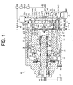
- variable displacement piston type compressor 16 A first preferred embodiment of a variable displacement piston type compressor 16 according to the present invention will now be described with reference to FIGS. 1 through 6B.
- the compressor 16 includes an aluminum front housing 12 which is fixedly connected to the front end of an aluminum cylinder 11 and an aluminum rear housing or a cover housing 13 which is fixedly connected to the rear end of the cylinder 11 through a valve port plate 14 and a valve plate 15.
- the cylinder 11, the front housing 12 and the rear housing 13 are fastened together by bolts 43.
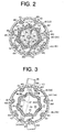
- the rear housing 13 has an outer peripheral wall 48 forming therein a plurality of threaded holes 481 each receiving therein a bolt 43.
- the cylinder 11, the front housing 12 and the rear housing 13 cooperatively form the housing of the variable displacement piston type compressor 16.
- the front housing 12 and the cylinder 11 form a crank chamber 121, and a rotary shaft 18 is rotatably supported by the front housing 12 and the cylinder 11 through radial bearings 19 and 20.
- the rotary shaft 18 protruding outside from the crank chamber 121 receives driving power from a vehicle engine or an external power source 17 through a pulley (not shown) and a belt (not shown).
- a rotor 21 is fixedly connected to the rotary shaft 18, while a swash plate 22 is supported so as to be slidable in the axial direction of the rotary shaft 18 and inclinable relative to the rotary shaft 18.
- a pair of coupling elements 23 is fixedly connected to the swash plate 22, and a guide pin 24 is fixedly connected to each connecting element 23.
- the rotor 21 forms therein a pair of guide holes 211, and the head of the guide pin 24 is slidably fitted into each guide hole 211.
- the swash plate 22 is slidable in the axial direction of the rotary shaft 18 and is rotatable integrally with the rotary shaft 18 due to coordinated movements of the guide holes 211 and the guide pins 24.
- the inclination of the swash plate 22 is guided by a slide-guide between the guide hole 211 and the guide pin 24 and a slide-support of the rotary shaft 18.
- the maximum inclination angle of the swash plate 22 is regulated by the contact between the rotor 21 and the swash plate 22.
- the position of the swash plate 22 indicated by the solid line in FIG. 1 shows a state of the maximum inclination angle of the swash plate 22.
- the position of the swash plate 22 indicated by the dotted line in FIG. 1 shows a state of the minimum inclination angle of the swash plate 22.
- a plurality of cylinder bores 111 is formed extending through the cylinder 11 and a piston 25 is received in each of the cylinder bores 111. Rotation of the swash plate 22 is converted to reciprocation of the piston 25 in the cylinder bore 111 through a pair of shoes 26.
- the piston 25 defines a compression chamber 112 in the cylinder bore 111.
- the rear housing 13 forms therein a suction chamber 27 and a discharge chamber 28 which are separated by an annular partition wall 29.
- the suction chamber 27, that is, a part of the suction pressure region of the compressor, is located on the radially outer side of the rear housing 13, surrounding the discharge chamber 28, that is, a part of the discharge pressure region around the axis 181 of the rotary shaft 18.
- a valve plate 30 and a retainer 31 are fastened to the valve port plate 14 in the discharge chamber 28 by a screw 32.
- the valve port plate 14 forms therein suction ports 141 and discharge ports 142.
- the valve plates 15 and 30 form therein suction valves 151 and discharge valves 301, respectively.
- the opening degree of the suction valve 151 is regulated by the bottom of a retaining recess 113 formed in the cylinder 11.
- gaseous refrigerant in the compression chamber 112 is discharged into the discharge chamber 28 through the discharge port 142 while pushing the discharge valve 301 open.
- the opening degree of the discharge valve 301 is regulated by the retainer 31.
- the rear housing 13 has an end wall 49 in which an insertion opening 53, a circular passage 45, a first communication passage 33, a second communication passage 34 and a discharge passage 47 are formed.
- the first communication passage 33 and the second communication passage 34 which are part of the suction pressure region, are in communication with the suction chamber 27, which is also a part of the suction pressure region.
- the discharge passage 47 is in communication with the discharge chamber 28.
- the first communication passage 33 and the second communication passage 34 extend in a direction which is parallel to the axis 181 of the rotary shaft 18.
- the circular passage 45 which is a part of the suction pressure region, has a circular cross-section and extends linearly from one outer peripheral portion of the rear housing 13 toward the opposite outer peripheral portion thereof.
- the circular passage 45 extends perpendicularly to the axis 181 of the rotary shaft 18.
- the first communication passage 33 extends in parallel to the axis 181 of the rotary shaft 18 and intersects the circular passage 45 near the proximal end (the upper side in FIG. 1) for connection therewith.
- the second communication passage 34 also extends in parallel to the axis 181 of the rotary shaft 18 and intersects the circular passage 45 near the distal end (the lower side in FIG. 1) for connection therewith.
- the circular passage 45 for introducing gaseous refrigerant into the suction chamber 27 and the discharge passage 47 for discharging gaseous refrigerant from the discharge chamber 28 are in communication through an external refrigerant circuit 35.
- a heat exchanger 36 for radiating heat from refrigerant, a fixed throttle 37, a heat exchanger 38 for transferring ambient heat to refrigerant, and an accumulator 39 are provided in the external refrigerant circuit 35.
- the accumulator 39 serves to send only gaseous refrigerant to the compressor.
- Refrigerant in the discharge chamber 28 flows through the discharge passage 47, the heat exchanger 36, the fixed throttle 37, the heat exchanger 38, the accumulator 39, the circular passage 45, the first communication passage 33 and the second communication passage 34 into the suction chamber 27.
- the discharge chamber 28 and the crank chamber 121 are in communication through a supply passage 40.
- the crank chamber 121 and the suction chamber 27 are in communication through a bleed passage 41. Refrigerant in the crank chamber 121 flows through the bleed passage 41 into the suction chamber 27.
- An electromagnetic control valve 42 is disposed in the supply passage 40.
- the control valve 42 When de-energized, the control valve 42 is in closed state where refrigerant is not allowed to flow, so that refrigerant is not supplied from the discharge chamber 28 through the supply passage 40 to the crank chamber 121. Since refrigerant in the crank chamber 121 flows out thereof through the bleed passage 41 to the suction chamber 27, the pressure in the crank chamber 121 decreases. Accordingly, the inclination angle of the swash plate 22 increases thereby to increase the displacement of the compressor.
- the control valve 42 When energized, the control valve 42 is in opened state where refrigerant is allowed to flow, so that refrigerant is supplied from the discharge chamber 28 through the supply passage 40 to the crank chamber 121.
- the pressure in the crank chamber 121 increases to reduce the inclination angle of the swash plate 22 thereby to reduce the displacement of the compressor.
- a heat-insulating member 44 is inserted in the suction chamber 27.
- the heat-insulating member 44 includes a chamber heat-insulating member 441 and passage heat-insulating members 442, 443.
- the chamber heat-insulating member 441 is disposed so as to cover an inner wall surface 482 of the outer peripheral wall 48, an inner wall surface 491 of the end wall 49 and an outer peripheral wall surface 291 of the partition wall 29.
- the passage heat-insulating members 442 and 443 are provided so as to cover passage wall surfaces 331 and 341 forming the first and second communication passages 33 and 34, respectively.
- the heat-insulating member 44 covers the wall surfaces (the inner wall surfaces 482, 491, the outer peripheral wall surface 291 and the passage wall surfaces 331, 341) forming the suction pressure region constituted of the suction chamber 27, the first communication passage 33 and the second communication passage 34.
- a surface 143 of the valve port plate 14 facing the suction chamber 27 is a part of the wall surface forming the suction pressure region.
- a heat-insulating member 46 is inserted in the discharge chamber 28.
- the heat-insulating member 46 includes a chamber heat-insulating member 461 and a passage heat-insulating member 462.
- the chamber heat-insulating member 461 is provided so as to cover an inner wall surface 492 of the end wall 49 and an inner peripheral wall surface 292.
- the passage heat-insulating member 462 is disposed so as to cover a peripheral wall surface 471 forming the discharge passage 47. That is, the heat-insulating member 46 covers the wall surface (the inner wall surface 492, 292 and the peripheral wall surface 471) forming the discharge pressure region constituted of the discharge chamber 28 and the discharge passage 47.
- the surface 143 of the valve port plate 14 facing the discharge chamber 28 is a part of the wall surface for forming the discharge pressure region.
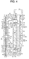
- a cylindrical member 50 made of insulating material is loosely fitted into the circular passage 45.
- the linear cylindrical member 50 is formed at its proximal end with a flange 501.
- the flange 501 contacts a step 451 between the insertion opening 53 and the circular passage 45 thereby to regulate the position of the cylindrical member 50 inserted into the circular passage 45.
- the cylindrical member 50 covers most of a peripheral wall surface 452 which forms the circular passage 45.
- the cylindrical member 50 defines therein an internal passage 51 which includes a first passage 511 and a second passage 512 which is smaller in diameter than the first passage 511.
- the second passage 512 is located downstream of the first passage 511 as seen in the direction in which the refrigerant flows.
- the cylindrical member 50 forms in the peripheral wall thereof communication holes 502, 503 as communicating portions.
- the communication hole 502 is in communication with the first passage 511, while the communication hole 503 is in communication with the second passage 512.
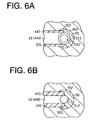
- the passage heat-insulating member 442 of the heat-insulating member 44 is fitted into (or engaged with) the communication hole 502, and an internal passage 444 of the passage heat-insulating member 442 is in communication with the first passage 511.
- the diameter of the communication hole 502 is substantially the same as the outer diameter of the passage heat-insulating member 442, so that the passage heat-insulating member 442 is tightly fitted into the communication hole 502.
- the diameter of the internal passage 444 is substantially the same as the diameter of the first passage 511. That is, the cross-sectional area of the internal passage 444 corresponds to that of the first passage 511.
- the internal passage 51 (the circular passage 45) of the cylindrical member 50 is located downstream of the external refrigerant circuit 35 with respect to the flow of refrigerant for communication therewith.
- the internal passage 444 (the first communication passage 33) which intersects the internal passage 51 (the circular passage 45) for connection therewith is communicable with the compression chamber 112 through the suction chamber 27 and the suction port 141.
- the passage heat-insulating member 443 of the heat-insulating member 44 is fitted into (or engaged with) the communication hole 503, and an internal passage 445 of the passage heat-insulating member 443 is in communication with the second passage 512.
- the diameter of the communication hole 503 is substantially the same as the outer diameter of the passage heat-insulating member 443, so that the passage heat-insulating member 443 is tightly fitted into the communication hole 503.
- the diameter of the internal passage 445 is substantially the same as that of the second passage 512. That is, the cross-sectional area of the internal passage 445 is substantially the same as that of the second passage 512.
- a seal ring 52 is provided upstream of the communication hole 502 between an outer peripheral wall surface 504 of the cylindrical member 50 and the peripheral wall surface 452 of the circular passage 45.
- Seal rings 54, 55 are provided between the outer peripheral wall surfaces of the passage heat-insulating members 442, 443 and the passage wall surfaces 331, 341 of the communication passages 33, 34, respectively.
- the heat-insulating members 44, 46 and the cylindrical member 50 are made of synthetic resin. Carbon dioxide is employed as refrigerant.
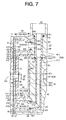
- FIG. 7 A second preferred embodiment of the present invention will now be described with reference to FIG. 7.
- the same reference numerals denote the substantially identical components or elements to those of the first preferred embodiment.
- a cylindrical member 50A which is made of insulating material and includes a cylindrical portion 56 corresponding to the first passage 511 and another cylindrical portion 57 corresponding to the second passage 512 is loosely fitted into a circular passage 45A.
- the outer diameter of the cylindrical portion 57 is smaller than that of the cylindrical portion 56.
- a passage heat-insulating member 442A has an end 446 which is connected to an outer peripheral wall surface 561 of the cylindrical portion 56 such that the internal passage 444 communicates with a communication hole 505.
- the inner diameter of the passage heat-insulating member 442A (the diameter of the internal passage 444) is substantially the same as the diameter of the communication hole 505.
- the cylindrical portion 571 has a distal end 571 which is beveled at an angle of 45 degrees.
- the passage heat-insulating member 443A has an end 447 which is also beveled at 45 degrees,
- the cylindrical portion 57 and the passage heat-insulating member 443A are connected together at their respective beveled ends 571, 447 so as to form an L joint as shown in FIG. 7.
- the outer diameter of the cylindrical portion 57 is substantially the same as that of the passage heat-insulating member 443A, and the inner diameter of the cylindrical portion 57 is also substantially the same as that of the passage heat-insulating member 443A (the diameter of the internal passage 445).
- the inner diameter of the passage heat-insulating member 442A (the diameter of the internal passage 444) is substantially the same as that of the passage heat-insulating member 443A (the diameter of the internal passage 445).
- the circular passage 45A is formed by a larger-diameter peripheral wall surface 60 corresponding to the cylindrical portion 56 and a smaller-diameter peripheral wall surface 61 corresponding to the cylindrical portion 57.
- a seal ring 59 is interposed between a step 62 formed between the peripheral wall surface 60 and the smaller diameter peripheral wall surface 61, and a step 58 formed between the cylindrical portion 56 and the cylindrical portion 57.
- the seal ring 59 is located downstream of the communication hole 505 with respect to the flowing direction of refrigerant gas.
- connection prevents the rotation of the cylindrical member 50A.
- the seal ring 59 prevents refrigerant gas from flowing between the peripheral wall surfaces 60, 61 of the circular passage 45 and the outer peripheral wall surface of the cylindrical member 50A.
- the internal passage 445 in the passage heat-insulating member 443A is formed with a diameter which is substantially the same as the diameter of the second passage 512, while the diameter of the internal passage 444 in the passage heat-insulating member 442A is substantially the same as the diameter of the internal passage 445. Therefore, the flow rate of gas in the first communication passage 33 (the internal passage 444) is substantially the same as the flow rate of gas in the second communication passage 34 (the internal passage 445), so that a decrease in the flow rate of gas in the second communication passage 34 (the internal passage 445), which is located downstream of the second passage 512, is prevented.
- a heat-insulating mechanism in a compressor which introduces refrigerant gas from a suction pressure region to a compression chamber and discharges the refrigerant gas from the compression chamber to a discharge pressure region has a circular passage, a communication passage, a cylindrical member and a passage heat-insulating member.
- the circular passage which is a portion of the suction pressure region, has a circular cross-section, and is in communication with an external refrigerant circuit.
- the communication passage which is a portion of the suction pressure region, intersects the circular passage for connection therewith, and is communicable with the compression chamber.
- the cylindrical member is fitted into the circular passage.
- the passage heat-insulating member made of an insulating material covers at least a portion of a passage wall surface which forms the communication passage. Rotation of the cylindrical member is prevented by engaging the passage heat-insulating member with the cylindrical member.
Landscapes
- Engineering & Computer Science (AREA)
- Mechanical Engineering (AREA)
- General Engineering & Computer Science (AREA)
- Compressor (AREA)
- Compressors, Vaccum Pumps And Other Relevant Systems (AREA)
- Applications Or Details Of Rotary Compressors (AREA)
Abstract
Description
Claims (9)
- A heat-insulating mechanism in a compressor which introduces refrigerant gas from a suction pressure region to a compression chamber and discharges the refrigerant gas from the compression chamber to a discharge pressure region, characterized in that a circular passage, which is a portion of the suction pressure region, having a circular cross-section is in communication with an external refrigerant circuit, in that a communication passage, which is a portion of the suction pressure region, intersects the circular passage for connection therewith and is communicable with the compression chamber, in that a cylindrical member is fitted into the circular passage, in that a passage heat-insulating member made of an insulating material covers at least a portion of a passage wall surface which forms the communication passage, and in that rotation of the cylindrical member is prevented by engaging the passage heat-insulating member with the cylindrical member.
- The heat-insulating mechanism according to claim 1, wherein the cylindrical member is loosely fitted into the circular passage.
- The heat-insulating mechanism according to any one of claims 1 and 2, wherein the compressor is a piston type in which the compression chamber is formed in a cylinder bore formed in a cylinder by accommodating a piston in the cylinder bore, the piston is reciprocated in the cylinder bore by rotation of a rotary shaft, and the suction pressure region and the discharge pressure region are formed in a cover housing connected to the cylinder, the cover housing forming the circular passage and the communication passage.
- The heat-insulating mechanism according to claim 3, wherein the suction pressure region is located on an outer peripheral side of the cover housing and surrounds the discharge pressure region around an axis of the rotary shaft.
- The heat-insulating mechanism according to any one of claims 3 and 4, wherein the communication passage includes:a first communication passage intersecting the circular passage for connection therewith; anda second communication passage located downstream of a connecting portion between the circular passage and the first communication passage, the second communication passage intersecting the circular passage for connection therewith.
- The heat-insulating mechanism according to claim 5, wherein an internal passage of the cylindrical member includes a first passage and a second passage having a smaller diameter than the first passage, the second passage being located downstream of the first passage, the first communication passage being in communication with the first passage, the second communication passage being in communication with the second passage.
- The heat-insulating mechanism according to any one of claims 5 and 6, characterized in that a seal ring is located upstream of a connecting portion between the first communication passage and the circular passage, and between an outer peripheral wall surface of the cylindrical member and a peripheral wall surface forming the circular passage so as to surround the cylindrical member.
- The heat-insulating mechanism according to any one of claims 3 through 7, characterized in that a suction chamber is provided in a portion of the suction pressure region and is located downstream of the communication passage to be in communication with the communication passage, in that a chamber heat-insulating member made of an insulating material covers at least a portion of a wall surface for forming the suction chamber, and in that the chamber heat-insulating member and the passage heat-insulating member are integrally formed.
- The heat-insulating mechanism according to any one of claims 1 through 8, wherein the refrigerant gas is carbon dioxide.
Applications Claiming Priority (2)
| Application Number | Priority Date | Filing Date | Title |
|---|---|---|---|
| JP2003387207A JP3979380B2 (en) | 2003-11-17 | 2003-11-17 | Thermal insulation structure in a compressor |
| JP2003387207 | 2003-11-17 |
Publications (2)
| Publication Number | Publication Date |
|---|---|
| EP1531265A2 true EP1531265A2 (en) | 2005-05-18 |
| EP1531265A3 EP1531265A3 (en) | 2006-01-18 |
Family
ID=34431537
Family Applications (1)
| Application Number | Title | Priority Date | Filing Date |
|---|---|---|---|
| EP04027216A Withdrawn EP1531265A3 (en) | 2003-11-17 | 2004-11-16 | Heat-insulating mechanism for compressor |
Country Status (3)
| Country | Link |
|---|---|
| US (1) | US7540720B2 (en) |
| EP (1) | EP1531265A3 (en) |
| JP (1) | JP3979380B2 (en) |
Families Citing this family (5)
| Publication number | Priority date | Publication date | Assignee | Title |
|---|---|---|---|---|
| BRPI0803457B1 (en) * | 2008-09-05 | 2020-11-10 | Embraco Indústria De Compressores E Soluções Em Refrigeração Ltda | suction arrangement for hermetic refrigeration compressor |
| JP5697024B2 (en) * | 2010-12-22 | 2015-04-08 | サンデン株式会社 | Compressor |
| US10094364B2 (en) * | 2015-03-24 | 2018-10-09 | Ocean Pacific Technologies | Banded ceramic valve and/or port plate |
| KR102215909B1 (en) * | 2019-08-23 | 2021-02-16 | 엘지전자 주식회사 | Linear compressor |
| KR102674873B1 (en) * | 2022-09-27 | 2024-06-14 | 엘지전자 주식회사 | Linear compressor |
Family Cites Families (9)
| Publication number | Priority date | Publication date | Assignee | Title |
|---|---|---|---|---|
| DE3332259A1 (en) | 1983-09-07 | 1985-03-28 | Danfoss A/S, Nordborg | REFRIGERATOR COMPRESSORS |
| JPH02264163A (en) | 1989-04-03 | 1990-10-26 | Hitachi Ltd | Refrigerant overheating preventive device for variable volume compressor |
| JP2911929B2 (en) | 1989-12-20 | 1999-06-28 | 富士通株式会社 | Interface circuit in private branch exchange |
| US5224840A (en) * | 1991-03-28 | 1993-07-06 | Tecumseh Products Company | Integral suction system |
| US5207563A (en) | 1991-05-20 | 1993-05-04 | Kabushiki Kaisha Toyoda Jidoshokki Seisakusho | Swash plate type compressor with a central discharge passage |
| JP3094732B2 (en) | 1993-04-30 | 2000-10-03 | 株式会社豊田自動織機製作所 | Reciprocating compressor |
| US5556260A (en) * | 1993-04-30 | 1996-09-17 | Kabushiki Kaisha Toyoda Jidoshokki Seisakusho | Multiple-cylinder piston type refrigerant compressor |
| GB2348678A (en) | 1997-08-29 | 2000-10-11 | Luk Farhrzeug Hydraulik Gmbh & | Swash plate compressor |
| DE19881579D2 (en) * | 1997-08-29 | 2000-10-12 | Luk Fahrzeug Hydraulik | Kompressor mit überlastenkopplungseinrichtung |
-
2003
- 2003-11-17 JP JP2003387207A patent/JP3979380B2/en not_active Expired - Fee Related
-
2004
- 2004-11-16 EP EP04027216A patent/EP1531265A3/en not_active Withdrawn
- 2004-11-16 US US10/990,234 patent/US7540720B2/en not_active Expired - Fee Related
Also Published As
| Publication number | Publication date |
|---|---|
| JP3979380B2 (en) | 2007-09-19 |
| US7540720B2 (en) | 2009-06-02 |
| US20050106033A1 (en) | 2005-05-19 |
| JP2005147021A (en) | 2005-06-09 |
| EP1531265A3 (en) | 2006-01-18 |
Similar Documents
| Publication | Publication Date | Title |
|---|---|---|
| US5765464A (en) | Reciprocating pistons of piston-type compressor | |
| CN101725498B (en) | Variable displacement type compressor with displacement control mechanism | |
| US7918656B2 (en) | Suction throttle valve of a compressor | |
| US6010313A (en) | Single-headed piston type compressor | |
| EP0809024B1 (en) | Reciprocating pistons of piston type compressor | |
| US6733246B2 (en) | Control device for variable displacement type compressor | |
| US7207185B2 (en) | Vehicle air conditioning apparatus | |
| US6871512B2 (en) | Motor-driven compressor | |
| US7540720B2 (en) | Heat-insulating mechanism for compressor | |
| US7281905B2 (en) | Piston type compressor | |
| JP4020068B2 (en) | Thermal insulation structure in a compressor | |
| EP2354548B1 (en) | Variable displacement type reciprocating compressor | |
| US20170211561A1 (en) | Variable displacement swash plate type compressor | |
| EP1553293A2 (en) | Heat insulating structure in piston type compressor | |
| US20010033798A1 (en) | Compressor | |
| CN103261688A (en) | compressor | |
| US20090097999A1 (en) | Suction structure in double-headed piston type compressor | |
| EP1275847B1 (en) | Restriction structure in variable displacement compressor | |
| US20050031459A1 (en) | Piston type compressor | |
| US7241116B2 (en) | Method of adjusting rotary machine | |
| US20040105762A1 (en) | Compressor in which heat transfer in a cylinder head is controlled | |
| JP5130187B2 (en) | Reciprocating compressor | |
| US20050031477A1 (en) | Discharge valve mechanism in compressor | |
| US12037995B2 (en) | Swash plate compressor | |
| US20180038359A1 (en) | Variable-displacement swash plate-type compressor |
Legal Events
| Date | Code | Title | Description |
|---|---|---|---|
| PUAI | Public reference made under article 153(3) epc to a published international application that has entered the european phase |
Free format text: ORIGINAL CODE: 0009012 |
|
| 17P | Request for examination filed |
Effective date: 20041116 |
|
| AK | Designated contracting states |
Kind code of ref document: A2 Designated state(s): AT BE BG CH CY CZ DE DK EE ES FI FR GB GR HU IE IS IT LI LU MC NL PL PT RO SE SI SK TR |
|
| AX | Request for extension of the european patent |
Extension state: AL HR LT LV MK YU |
|
| PUAL | Search report despatched |
Free format text: ORIGINAL CODE: 0009013 |
|
| AK | Designated contracting states |
Kind code of ref document: A3 Designated state(s): AT BE BG CH CY CZ DE DK EE ES FI FR GB GR HU IE IS IT LI LU MC NL PL PT RO SE SI SK TR |
|
| AX | Request for extension of the european patent |
Extension state: AL HR LT LV MK YU |
|
| RIC1 | Information provided on ipc code assigned before grant |
Ipc: F04B 39/12 20060101ALI20051201BHEP Ipc: F04B 39/06 20060101ALI20051201BHEP Ipc: F04B 27/10 20060101ALI20051201BHEP Ipc: F04B 27/08 20060101AFI20050224BHEP |
|
| AKX | Designation fees paid |
Designated state(s): DE FR IT |
|
| 17Q | First examination report despatched |
Effective date: 20060905 |
|
| GRAP | Despatch of communication of intention to grant a patent |
Free format text: ORIGINAL CODE: EPIDOSNIGR1 |
|
| STAA | Information on the status of an ep patent application or granted ep patent |
Free format text: STATUS: THE APPLICATION IS DEEMED TO BE WITHDRAWN |
|
| 18D | Application deemed to be withdrawn |
Effective date: 20100126 |