EP1531191A2 - Atomic layer deposition process and apparatus - Google Patents
Atomic layer deposition process and apparatus Download PDFInfo
- Publication number
- EP1531191A2 EP1531191A2 EP04256919A EP04256919A EP1531191A2 EP 1531191 A2 EP1531191 A2 EP 1531191A2 EP 04256919 A EP04256919 A EP 04256919A EP 04256919 A EP04256919 A EP 04256919A EP 1531191 A2 EP1531191 A2 EP 1531191A2
- Authority
- EP
- European Patent Office
- Prior art keywords
- precursor gas
- process reactor
- chamber
- reactor chamber
- auxiliary chamber
- Prior art date
- Legal status (The legal status is an assumption and is not a legal conclusion. Google has not performed a legal analysis and makes no representation as to the accuracy of the status listed.)
- Withdrawn
Links
- 238000000034 method Methods 0.000 title claims abstract description 109
- 238000000231 atomic layer deposition Methods 0.000 title claims abstract description 24
- 230000008569 process Effects 0.000 title claims description 88
- 239000002243 precursor Substances 0.000 claims abstract description 90
- 239000007789 gas Substances 0.000 claims description 108
- QGZKDVFQNNGYKY-UHFFFAOYSA-N Ammonia Chemical compound N QGZKDVFQNNGYKY-UHFFFAOYSA-N 0.000 claims description 20
- 239000000758 substrate Substances 0.000 claims description 16
- XJDNKRIXUMDJCW-UHFFFAOYSA-J titanium tetrachloride Chemical compound Cl[Ti](Cl)(Cl)Cl XJDNKRIXUMDJCW-UHFFFAOYSA-J 0.000 claims description 15
- 229910003074 TiCl4 Inorganic materials 0.000 claims description 6
- 229910021529 ammonia Inorganic materials 0.000 claims description 6
- 238000010926 purge Methods 0.000 claims description 6
- 229910000069 nitrogen hydride Inorganic materials 0.000 claims description 5
- XKRFYHLGVUSROY-UHFFFAOYSA-N Argon Chemical compound [Ar] XKRFYHLGVUSROY-UHFFFAOYSA-N 0.000 claims description 4
- 239000011261 inert gas Substances 0.000 claims description 4
- JLTRXTDYQLMHGR-UHFFFAOYSA-N trimethylaluminium Chemical compound C[Al](C)C JLTRXTDYQLMHGR-UHFFFAOYSA-N 0.000 claims description 3
- 229910004537 TaCl5 Inorganic materials 0.000 claims description 2
- 229910007932 ZrCl4 Inorganic materials 0.000 claims description 2
- 229910052786 argon Inorganic materials 0.000 claims description 2
- OEIMLTQPLAGXMX-UHFFFAOYSA-I tantalum(v) chloride Chemical compound Cl[Ta](Cl)(Cl)(Cl)Cl OEIMLTQPLAGXMX-UHFFFAOYSA-I 0.000 claims description 2
- MNWRORMXBIWXCI-UHFFFAOYSA-N tetrakis(dimethylamido)titanium Chemical compound CN(C)[Ti](N(C)C)(N(C)C)N(C)C MNWRORMXBIWXCI-UHFFFAOYSA-N 0.000 claims description 2
- DUNKXUFBGCUVQW-UHFFFAOYSA-J zirconium tetrachloride Chemical compound Cl[Zr](Cl)(Cl)Cl DUNKXUFBGCUVQW-UHFFFAOYSA-J 0.000 claims description 2
- 229910003865 HfCl4 Inorganic materials 0.000 claims 1
- 125000001495 ethyl group Chemical group [H]C([H])([H])C([H])([H])* 0.000 claims 1
- PDPJQWYGJJBYLF-UHFFFAOYSA-J hafnium tetrachloride Chemical compound Cl[Hf](Cl)(Cl)Cl PDPJQWYGJJBYLF-UHFFFAOYSA-J 0.000 claims 1
- 238000005086 pumping Methods 0.000 abstract description 7
- 238000000151 deposition Methods 0.000 description 9
- 230000008021 deposition Effects 0.000 description 8
- 239000010410 layer Substances 0.000 description 7
- 239000010408 film Substances 0.000 description 6
- 239000007788 liquid Substances 0.000 description 5
- 239000000463 material Substances 0.000 description 5
- 238000005259 measurement Methods 0.000 description 5
- XUIMIQQOPSSXEZ-UHFFFAOYSA-N Silicon Chemical compound [Si] XUIMIQQOPSSXEZ-UHFFFAOYSA-N 0.000 description 4
- 229910052710 silicon Inorganic materials 0.000 description 4
- 239000010703 silicon Substances 0.000 description 4
- 239000007787 solid Substances 0.000 description 4
- 239000000126 substance Substances 0.000 description 4
- NRTOMJZYCJJWKI-UHFFFAOYSA-N Titanium nitride Chemical group [Ti]#N NRTOMJZYCJJWKI-UHFFFAOYSA-N 0.000 description 3
- 230000007423 decrease Effects 0.000 description 3
- 239000010409 thin film Substances 0.000 description 3
- XLYOFNOQVPJJNP-UHFFFAOYSA-N water Chemical compound O XLYOFNOQVPJJNP-UHFFFAOYSA-N 0.000 description 3
- 238000009530 blood pressure measurement Methods 0.000 description 2
- NFHFRUOZVGFOOS-UHFFFAOYSA-N palladium;triphenylphosphane Chemical compound [Pd].C1=CC=CC=C1P(C=1C=CC=CC=1)C1=CC=CC=C1.C1=CC=CC=C1P(C=1C=CC=CC=1)C1=CC=CC=C1.C1=CC=CC=C1P(C=1C=CC=CC=1)C1=CC=CC=C1.C1=CC=CC=C1P(C=1C=CC=CC=1)C1=CC=CC=C1 NFHFRUOZVGFOOS-UHFFFAOYSA-N 0.000 description 2
- 239000002356 single layer Substances 0.000 description 2
- 229910001220 stainless steel Inorganic materials 0.000 description 2
- 239000010935 stainless steel Substances 0.000 description 2
- 230000008016 vaporization Effects 0.000 description 2
- 238000009834 vaporization Methods 0.000 description 2
- 239000002699 waste material Substances 0.000 description 2
- ZLOKVAIRQVQRGC-UHFFFAOYSA-N CN(C)[Ti] Chemical compound CN(C)[Ti] ZLOKVAIRQVQRGC-UHFFFAOYSA-N 0.000 description 1
- 230000008901 benefit Effects 0.000 description 1
- 238000006243 chemical reaction Methods 0.000 description 1
- 238000005137 deposition process Methods 0.000 description 1
- VBCSQFQVDXIOJL-UHFFFAOYSA-N diethylazanide;hafnium(4+) Chemical compound [Hf+4].CC[N-]CC.CC[N-]CC.CC[N-]CC.CC[N-]CC VBCSQFQVDXIOJL-UHFFFAOYSA-N 0.000 description 1
- TUTOKIOKAWTABR-UHFFFAOYSA-N dimethylalumane Chemical compound C[AlH]C TUTOKIOKAWTABR-UHFFFAOYSA-N 0.000 description 1
- ZYLGGWPMIDHSEZ-UHFFFAOYSA-N dimethylazanide;hafnium(4+) Chemical compound [Hf+4].C[N-]C.C[N-]C.C[N-]C.C[N-]C ZYLGGWPMIDHSEZ-UHFFFAOYSA-N 0.000 description 1
- 230000000694 effects Effects 0.000 description 1
- NPEOKFBCHNGLJD-UHFFFAOYSA-N ethyl(methyl)azanide;hafnium(4+) Chemical compound [Hf+4].CC[N-]C.CC[N-]C.CC[N-]C.CC[N-]C NPEOKFBCHNGLJD-UHFFFAOYSA-N 0.000 description 1
- 150000002363 hafnium compounds Chemical class 0.000 description 1
- 238000004519 manufacturing process Methods 0.000 description 1
- 230000007246 mechanism Effects 0.000 description 1
- 238000012986 modification Methods 0.000 description 1
- 230000004048 modification Effects 0.000 description 1
- 230000004044 response Effects 0.000 description 1
- 238000001179 sorption measurement Methods 0.000 description 1
- 239000010936 titanium Substances 0.000 description 1
- 229910001868 water Inorganic materials 0.000 description 1
- 229910052727 yttrium Inorganic materials 0.000 description 1
- VWQVUPCCIRVNHF-UHFFFAOYSA-N yttrium atom Chemical compound [Y] VWQVUPCCIRVNHF-UHFFFAOYSA-N 0.000 description 1
Images


Classifications
-
- C—CHEMISTRY; METALLURGY
- C23—COATING METALLIC MATERIAL; COATING MATERIAL WITH METALLIC MATERIAL; CHEMICAL SURFACE TREATMENT; DIFFUSION TREATMENT OF METALLIC MATERIAL; COATING BY VACUUM EVAPORATION, BY SPUTTERING, BY ION IMPLANTATION OR BY CHEMICAL VAPOUR DEPOSITION, IN GENERAL; INHIBITING CORROSION OF METALLIC MATERIAL OR INCRUSTATION IN GENERAL
- C23C—COATING METALLIC MATERIAL; COATING MATERIAL WITH METALLIC MATERIAL; SURFACE TREATMENT OF METALLIC MATERIAL BY DIFFUSION INTO THE SURFACE, BY CHEMICAL CONVERSION OR SUBSTITUTION; COATING BY VACUUM EVAPORATION, BY SPUTTERING, BY ION IMPLANTATION OR BY CHEMICAL VAPOUR DEPOSITION, IN GENERAL
- C23C16/00—Chemical coating by decomposition of gaseous compounds, without leaving reaction products of surface material in the coating, i.e. chemical vapour deposition [CVD] processes
- C23C16/44—Chemical coating by decomposition of gaseous compounds, without leaving reaction products of surface material in the coating, i.e. chemical vapour deposition [CVD] processes characterised by the method of coating
- C23C16/455—Chemical coating by decomposition of gaseous compounds, without leaving reaction products of surface material in the coating, i.e. chemical vapour deposition [CVD] processes characterised by the method of coating characterised by the method used for introducing gases into reaction chamber or for modifying gas flows in reaction chamber
- C23C16/45523—Pulsed gas flow or change of composition over time
- C23C16/45525—Atomic layer deposition [ALD]
- C23C16/45544—Atomic layer deposition [ALD] characterized by the apparatus
-
- C—CHEMISTRY; METALLURGY
- C23—COATING METALLIC MATERIAL; COATING MATERIAL WITH METALLIC MATERIAL; CHEMICAL SURFACE TREATMENT; DIFFUSION TREATMENT OF METALLIC MATERIAL; COATING BY VACUUM EVAPORATION, BY SPUTTERING, BY ION IMPLANTATION OR BY CHEMICAL VAPOUR DEPOSITION, IN GENERAL; INHIBITING CORROSION OF METALLIC MATERIAL OR INCRUSTATION IN GENERAL
- C23C—COATING METALLIC MATERIAL; COATING MATERIAL WITH METALLIC MATERIAL; SURFACE TREATMENT OF METALLIC MATERIAL BY DIFFUSION INTO THE SURFACE, BY CHEMICAL CONVERSION OR SUBSTITUTION; COATING BY VACUUM EVAPORATION, BY SPUTTERING, BY ION IMPLANTATION OR BY CHEMICAL VAPOUR DEPOSITION, IN GENERAL
- C23C16/00—Chemical coating by decomposition of gaseous compounds, without leaving reaction products of surface material in the coating, i.e. chemical vapour deposition [CVD] processes
- C23C16/22—Chemical coating by decomposition of gaseous compounds, without leaving reaction products of surface material in the coating, i.e. chemical vapour deposition [CVD] processes characterised by the deposition of inorganic material, other than metallic material
- C23C16/30—Deposition of compounds, mixtures or solid solutions, e.g. borides, carbides, nitrides
- C23C16/34—Nitrides
-
- C—CHEMISTRY; METALLURGY
- C23—COATING METALLIC MATERIAL; COATING MATERIAL WITH METALLIC MATERIAL; CHEMICAL SURFACE TREATMENT; DIFFUSION TREATMENT OF METALLIC MATERIAL; COATING BY VACUUM EVAPORATION, BY SPUTTERING, BY ION IMPLANTATION OR BY CHEMICAL VAPOUR DEPOSITION, IN GENERAL; INHIBITING CORROSION OF METALLIC MATERIAL OR INCRUSTATION IN GENERAL
- C23C—COATING METALLIC MATERIAL; COATING MATERIAL WITH METALLIC MATERIAL; SURFACE TREATMENT OF METALLIC MATERIAL BY DIFFUSION INTO THE SURFACE, BY CHEMICAL CONVERSION OR SUBSTITUTION; COATING BY VACUUM EVAPORATION, BY SPUTTERING, BY ION IMPLANTATION OR BY CHEMICAL VAPOUR DEPOSITION, IN GENERAL
- C23C16/00—Chemical coating by decomposition of gaseous compounds, without leaving reaction products of surface material in the coating, i.e. chemical vapour deposition [CVD] processes
- C23C16/44—Chemical coating by decomposition of gaseous compounds, without leaving reaction products of surface material in the coating, i.e. chemical vapour deposition [CVD] processes characterised by the method of coating
- C23C16/455—Chemical coating by decomposition of gaseous compounds, without leaving reaction products of surface material in the coating, i.e. chemical vapour deposition [CVD] processes characterised by the method of coating characterised by the method used for introducing gases into reaction chamber or for modifying gas flows in reaction chamber
- C23C16/45557—Pulsed pressure or control pressure
Definitions
- This invention is directed to atomic layer deposition. More particularly this invention provides an apparatus and process in which precursor gas is delivered to a process reactor chamber at reduced pressure from an auxiliary chamber through a pressure equalization process. The precursor gas flows into the reactor chamber from the auxiliary chamber solely due to a pressure gradient between the two chambers thereby reducing use of excess precursor gas and ensuring spatial uniformity of layers produced in the atomic layer deposition process.
- Atomic layer deposition is a method of depositing very thin films onto a surface. Individual precursor gases are pulsed onto the surface, typically a wafer, in a sequential manner without mixing the precursors in the gas phase. Each precursor gas reacts with the surface to form an atomic layer in a way such that only one layer at a time can be deposited onto the surface.
- each of the precursor gases reacts with each other only at surfaces where they are deliberately deposited.
- introduction of precursor gases to the process reactor chamber is often interleaved with a flow of purge gas.
- the major portion of the precursor gas delivered is not used to form the monolayer, but flowed through the system and thus wasted.
- the relatively slow time response of mass flow controllers used to meter the precursor gas into the process reactor chamber is a contributing factor to the inefficiency of gas usage.
- mass flow controllers are set to deliver a predetermined flow to a process reactor chamber as part of the atomic layer process, the flow is often kept constant and merely switched between the process reactor chamber and a disposal pump.
- this procedure results in pumping problems due to volume reactions in the foreline, the pumps and the abatement system.
- the present invention provides an atomic layer deposition arrangement comprising a process reactor chamber having at least one inlet and at least one outlet, a first auxiliary chamber for receiving a first precursor gas coupled to the process reactor chamber through a first flow path, at least one precursor gas valve in the first flow path between an inlet of the process reactor chamber and the auxiliary chamber, a second auxiliary chamber for receiving a second precursor gas coupled to the process reactor chamber through a second flow path, at least one second precursor gas valve in the second flow path between an inlet of the process reactor chamber and the second auxiliary chamber, and an exhaust pump coupled to the at least one outlet of the process reactor chamber.
- the first flow path and second flow path do not include a mass flow controller.
- the present invention provides a method of delivering precursor gas to an atomic layer deposition chamber comprising closing a first precursor gas valve located in between a first auxiliary chamber and an inlet of a process reactor chamber, closing a second precursor gas valve located in between a second auxiliary chamber and an inlet of the process reactor chamber, reducing pressure in the process reactor chamber, opening the first precursor gas valve, allowing a first precursor gas to flow from the first auxiliary chamber to the process reactor chamber solely under a pressure gradient, closing the first precursor gas valve, reducing pressure in the process reactor chamber, opening the second precursor gas valve, and allowing a second precursor gas to flow from the second auxiliary chamber to an inlet of the process reactor chamber solely under a pressure gradient.
- a method of delivering a first precursor gas to a process reactor chamber 10 is illustrated in Figure 1.
- the process reactor chamber 10 is coupled to an exhaust pump (not shown) via a vacuum valve 12 coupled to an outlet 14 of the process reactor chamber 10.
- the process reactor chamber 10 is also coupled through inlets 16 and 18 to a first auxiliary chamber 20 having a volume V 1 containing a first precursor gas and a second auxiliary chamber 22 having a volume V 2 containing a second precursor gas.
- Gas valves 24 and 26 are located in between the first auxiliary chamber 20 and process reactor chamber inlet 16, and in between the second auxiliary chamber 22 and process reactor chamber inlet 18, respectively.
- valve 24 is opened and the first precursor gas discharges from first auxiliary chamber 20 into process reactor chamber 10 due to the pressure gradient between first auxiliary chamber 20 and process reactor chamber 10.
- Fig. 1(b) Apportionment of the first precursor gas between first auxiliary chamber 20 and process reactor chamber 10 is illustrated in Fig. 1(b).
- valve 24 is closed as illustrated in Fig. 1(c).
- Valve 12 is then opened and pressure reduced in process reactor 10 as shown in Fig. 1(d).
- valve 12 is closed as shown in Fig. I(e) and Fig. 2(a).
- valve 26 is opened and the second precursor gas discharges from the second auxiliary chamber 22 into process reactor chamber 10 due to the pressure gradient between the second auxiliary chamber 22 and process reactor chamber 10.
- P 2 is the pressure in auxiliary chamber 22 before discharge and Pr 2 is the pressure in the second auxiliary chamber and process reactor chamber after discharge.
- valve 26 is closed as illustrated in Fig. 2(c).
- Valve 12 is then opened and pressure reduced in process reactor chamber 10 as shown in Fig. 2(d).
- valve 12 is closed as shown in Fig. 2(e).
- the first auxiliary chamber 20 and second auxiliary chamber 22 may be coupled by an intermittent valve connection to any suitable gas supply and recharged in between alternating discharge of the first precursor gas and second precursor gas to the process reactor chamber.
- the gas supply source can be a pressurized gas source such as a gas cylinder or a chamber including a solid or liquid substance.
- the chamber is heated to vaporize the substance and obtain a desired vapor pressure.
- the first auxiliary chamber 20 and second auxiliary chamber 22 may itself contain a solid or liquid substance and be heated to a predetermined temperature to vaporize the substance and obtain the desired vapor pressure.
- process reactor chamber 10 may be purged with an inert gas after evacuation as in Fig. 1(d) or Fig. 2(d) and prior to introduction of an alternate precursor gas as in Fig. 1(b) of Fig. 2(b).
- Precursors for use in ALD are well known to those skilled in the art.
- Examples of commonly used precursors include Zr(OC 4 H 9 ) 4 and O 2 , ZrCl 4 and H 2 O, HfCI 4 and H 2 O, 2,2,6,6-tetramethyl-3,5-heptanedionato Yttrium ("Y(thd) 3 ") and O 3, Al(CH 3 ) 3 and H 2 O, Al(CH 3 ) 3 and O 2 , dimethylaluminumhydride ethylene-piperidine-pyrocatechol ("DMAH-EPP”) and NH 3, tetrakis dimethylamino titanium (“TDMAT”) and NH 3 , TiCl 4 and NH 3, TiCl 4 and H 2 /N 2, TiCl 4 and H 2 , TiCl 4 and H 2 O, TiCl 4 and O 2 , Ti(OCH(CH 3 ) 2 )) 4 and O 2 , TaCl 5 and NH 3 , Ta(OC 2
- FIG. 3 illustrates an embodiment for the manufacture of thin films.
- a substrate holder 30 which can be heated by electrical power to a predetermined temperature. This temperature is referred to as the deposition temperature.
- a substrate 32 is mounted on the substrate holder such that good thermal contact is established between substrate holder 30 and substrate 32.
- the process reactor chamber 10 is made of stainless steel and is vacuum-pumped by a vacuum pumping system (not shown).
- the vacuum system pumping system is connected to the process reactor chamber 10 by means of a high conductance vacuum valve 12.
- Vacuum valve 12 is either in an open or closed position, transitioning between these states with a fast acting mechanism.
- the connecting vacuum valve is manufactured by BOC Edwards, model number QVA060.
- the interior of the process reactor chamber 10 is pumped down to a base pressure of 10 -5 Torr by the evacuation system when vacuum valve 12 is in its open position.
- the pressure of process reactor chamber 10 is typically less than 10 -3 Torr 10 minutes after vacuum valve 12 has been closed, indicating leak tightness of the vessel. In normal operation, there is no provision to either measure or control the pressure of process reactor chamber 10.
- the process reactor chamber 10 is connected to a source-material delivery system consisting of two vessels 20 and 22 connected by gas valves 24 and 26 respectively, to the process reactor chamber 10.
- Vessels 20 and 22 are made of stainless steel.
- Vessel 20 and its connecting valve 24 can be electrically heated to temperatures up to 300° C.
- the connecting high temperature valve is provided by Fujikin, model number FWBR-71-9.52.
- Vessels 20 and 22 are connected via valves 34 and 36, respectively to sources of material at constant pressure. In the case that two gases are used, these sources are usually gas cylinders with regulators to ensure a constant delivery pressure.
- one of the sources is liquid or solid at room temperature, precursor material is preloaded into vessel 20 through either valve 34 or through a fill opening in the wall of vessel 20 which can be closed gas tight.
- the net volume enclosed between valves 24, 26 and 12 is 378 cc.
- Low vapor pressure materials either liquids or solids are loaded in vessel 20.
- This vessel and valve 24 are heated to a predetermined temperature referred to as the vaporization temperature.
- the net volume of vessel 20 is 231 cc and the volume of vessel 22 is 37 cc.
- a system controller typically a computer, a programmable logic controller (PLC) or a microprocessor.
- PLC programmable logic controller
- one of the source materials used is titaniumtetrachloride while the second gas is ammonia gas.
- Thirty cc of titaniumtetrachloride is loaded at room temperature as a liquid into vessel 20.
- the ammonia gas is supplied to vessel 22 from a gas cylinder with a regulator set at 30 psi (gauge pressure).
- the deposition process is started by affixing a silicon wafer which is the substrate 32, to the substrate holder 30, then closing valves 24 and 26 and opening the vacuum valve 12, thus evacuating the process reactor chamber.
- the substrate holder 30 and, by inference the substrate 32, is heated to the deposition temperature of 400° C.
- valve 26 is briefly opened to evacuate vessel 22 and closed. When valve 26 has reached closure, valve 36 is opened for a time long enough for vessel 22 to be charged with ammonia gas at a pressure of 30 psi. In this system, valve 26 is kept open for 2 seconds. Valve 36 is opened and closed at regular intervals to keep the vessel 22 charged at 30 psi.
- valve 12 is closed and when it reaches closure valve 24 is opened, kept open for 1 second and then closed. From previous diagnostic pressure measurements, it is known that the process vessel is now filled with titaniumtetrachloride at a pressure between 10 and 20 Torr. One second after valve 24 reaches closure, valve 12 is opened for 15 seconds and then closed. From previous measurements it is known that the pressure of titanium chloride in the process vessel is now less than 10 -4 Torr. At the moment that valve 12 reaches closure, valve 26 is opened for 1 second. From previous diagnostic pressure measurements it is known that ammonia is now present in the process vessel at a pressure of 20 Torr. One second after valve 26 reaches closure, valve 12 is opened for 15 seconds and then closed. From previous measurements it is known that the pressure of ammonia in the process vessel is now less than 10 -4 Torr.
- This sequence has exposed the surface of the silicon wafer 32 to titaniumtetrachloride and to ammonia, respectively, under isobaric conditions.
- This complete cycle is referred to as one deposition cycle.
- a monolayer of a film which is substantially titanium nitride is uniformly deposited on the surface of the silicon wafer 32.
- a desired film thickness is obtained by repeating the deposition cycle a sufficient number of times. After 50 deposition cycles all valves are closed, the substrate temperature is allowed to decrease to room temperature and the process reactor chamber 10 is vented to atmospheric pressure.
- the silicon wafer substrate with the titanium nitride film is removed from the system and the deposited film is measured for thickness uniformity across the wafer surface. The thickness uniformity is found to be better than the measurement error of the measurement apparatus and the non-uniformity is estimated to be less than 1%.
- a third vessel 38 with internal volume of 73 cc but otherwise identical to the vessels 20 and 22 is charged with 150 psi (gauge pressure) of argon.
- This vessel is discharged to process reactor chamber 10 right after valve 12 is opened to drive the titaniumtetrachloride and then the ammonia out of the system and decrease the pumping time to 5 seconds instead of 15 seconds in both cases.
- the invention has the desirable effect of improving the thickness uniformity of a film deposited by means of an atomic layer deposition method whereby the gases are in contact with the substrate surface under conditions of zero flow.
- Another advantage of this invention is the simplicity of the apparatus because the process obviates the need for complicated measurements of flow and pressure.
- the atomic layer deposition arrangement and process of the invention minimizes waste of precursor gases, decreases process costs and minimizes problems associated with delivery of precursor gas to the process reactor chamber by pumping.
- the adsorption of precursor gas by a substrate in a process without gas flow by pumping ensures the spatial uniformity of the layer deposited on the substrate.
Abstract


Description
- This invention is directed to atomic layer deposition. More particularly this invention provides an apparatus and process in which precursor gas is delivered to a process reactor chamber at reduced pressure from an auxiliary chamber through a pressure equalization process. The precursor gas flows into the reactor chamber from the auxiliary chamber solely due to a pressure gradient between the two chambers thereby reducing use of excess precursor gas and ensuring spatial uniformity of layers produced in the atomic layer deposition process.
- Atomic layer deposition is a method of depositing very thin films onto a surface. Individual precursor gases are pulsed onto the surface, typically a wafer, in a sequential manner without mixing the precursors in the gas phase. Each precursor gas reacts with the surface to form an atomic layer in a way such that only one layer at a time can be deposited onto the surface.
- Preferably, each of the precursor gases reacts with each other only at surfaces where they are deliberately deposited. To avoid direct contact between the different precursor gases, introduction of precursor gases to the process reactor chamber is often interleaved with a flow of purge gas.
- There are several drawbacks to current procedures for introducing precursor gas to the process reactor chamber. The thickness of the layer of precursor adsorbed onto the target surface depends upon the gas impingement rate on the target surface, and thus the local pressure. When precursor gas is delivered over a flow line, the pressure varies over the flow line and consequently, the gas will not be adsorbed uniformly over the target surface.
- Second, the major portion of the precursor gas delivered is not used to form the monolayer, but flowed through the system and thus wasted. The relatively slow time response of mass flow controllers used to meter the precursor gas into the process reactor chamber is a contributing factor to the inefficiency of gas usage. In fact, after mass flow controllers are set to deliver a predetermined flow to a process reactor chamber as part of the atomic layer process, the flow is often kept constant and merely switched between the process reactor chamber and a disposal pump. In addition to the enormous waste of precursor gas, this procedure results in pumping problems due to volume reactions in the foreline, the pumps and the abatement system.
- In a first aspect, the present invention provides an atomic layer deposition arrangement comprising a process reactor chamber having at least one inlet and at least one outlet, a first auxiliary chamber for receiving a first precursor gas coupled to the process reactor chamber through a first flow path, at least one precursor gas valve in the first flow path between an inlet of the process reactor chamber and the auxiliary chamber, a second auxiliary chamber for receiving a second precursor gas coupled to the process reactor chamber through a second flow path, at least one second precursor gas valve in the second flow path between an inlet of the process reactor chamber and the second auxiliary chamber, and an exhaust pump coupled to the at least one outlet of the process reactor chamber. The first flow path and second flow path do not include a mass flow controller.
- In a second aspect the present invention provides a method of delivering precursor gas to an atomic layer deposition chamber comprising closing a first precursor gas valve located in between a first auxiliary chamber and an inlet of a process reactor chamber, closing a second precursor gas valve located in between a second auxiliary chamber and an inlet of the process reactor chamber, reducing pressure in the process reactor chamber, opening the first precursor gas valve, allowing a first precursor gas to flow from the first auxiliary chamber to the process reactor chamber solely under a pressure gradient, closing the first precursor gas valve, reducing pressure in the process reactor chamber, opening the second precursor gas valve, and allowing a second precursor gas to flow from the second auxiliary chamber to an inlet of the process reactor chamber solely under a pressure gradient.
- Preferred features of the present invention will now be described, by way of example only, with reference to the accompanying drawings, in which:-
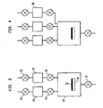
- Figure 1(a)-1(e) are schematic representations of a method and arrangement for delivery of a first precursor gas;
- Figure 2(a)-2(e) are schematic representations of a method and arrangement for delivery of a second precursor gas;
- Figure 3 is an illustration of an atomic layer deposition arrangement; and
- Figure 4 is an illustration of an atomic layer deposition arrangement including a purge gas.
-
- A method of delivering a first precursor gas to a
process reactor chamber 10 is illustrated in Figure 1. Theprocess reactor chamber 10 is coupled to an exhaust pump (not shown) via avacuum valve 12 coupled to anoutlet 14 of theprocess reactor chamber 10. Theprocess reactor chamber 10 is also coupled throughinlets auxiliary chamber 20 having a volume V1 containing a first precursor gas and a secondauxiliary chamber 22 having a volume V2 containing a second precursor gas.Gas valves auxiliary chamber 20 and processreactor chamber inlet 16, and in between the secondauxiliary chamber 22 and processreactor chamber inlet 18, respectively. - In this method, the pressure in
process reactor chamber 10 is reduced byopening valve 12 coupled to the exhaust pump withvalves valve 24 is opened and the first precursor gas discharges from firstauxiliary chamber 20 intoprocess reactor chamber 10 due to the pressure gradient between firstauxiliary chamber 20 andprocess reactor chamber 10. The first precursor gas will apportion itself betweenprocess reactor chamber 10 and firstauxiliary chamber 20 according to chamber volumes, approximately in accordance with the following equation, - Apportionment of the first precursor gas between first
auxiliary chamber 20 andprocess reactor chamber 10 is illustrated in Fig. 1(b). After discharge of the first precursor gas into theprocess reactor chamber 10,valve 24 is closed as illustrated in Fig. 1(c).Valve 12 is then opened and pressure reduced inprocess reactor 10 as shown in Fig. 1(d). After a reduced pressure is achieved inprocess reactor 10,valve 12 is closed as shown in Fig. I(e) and Fig. 2(a). - Next, as shown in Fig. 2(b),
valve 26 is opened and the second precursor gas discharges from the secondauxiliary chamber 22 intoprocess reactor chamber 10 due to the pressure gradient between the secondauxiliary chamber 22 andprocess reactor chamber 10. The second precursor gas will apportion itself betweenprocess reactor 10 and secondauxiliary chamber 22 according to chamber volume, approximately in accordance with the following equation - Where P2 is the pressure in
auxiliary chamber 22 before discharge and Pr2 is the pressure in the second auxiliary chamber and process reactor chamber after discharge. After discharge of the second precursor gas into theprocess reactor chamber 10,valve 26 is closed as illustrated in Fig. 2(c).Valve 12 is then opened and pressure reduced inprocess reactor chamber 10 as shown in Fig. 2(d). After a reduced pressure is achieved inprocess reactor 10,valve 12 is closed as shown in Fig. 2(e). - The above is repeated, alternating gas discharge from first
auxiliary chamber 20 and secondauxiliary chamber 22 until the desired thickness of deposition layer is obtained. - The first
auxiliary chamber 20 and secondauxiliary chamber 22 may be coupled by an intermittent valve connection to any suitable gas supply and recharged in between alternating discharge of the first precursor gas and second precursor gas to the process reactor chamber. - As is well known by those of skill in the art, the gas supply source can be a pressurized gas source such as a gas cylinder or a chamber including a solid or liquid substance. The chamber is heated to vaporize the substance and obtain a desired vapor pressure. The first
auxiliary chamber 20 and secondauxiliary chamber 22 may itself contain a solid or liquid substance and be heated to a predetermined temperature to vaporize the substance and obtain the desired vapor pressure. - Optionally,
process reactor chamber 10 may be purged with an inert gas after evacuation as in Fig. 1(d) or Fig. 2(d) and prior to introduction of an alternate precursor gas as in Fig. 1(b) of Fig. 2(b). - Precursors for use in ALD are well known to those skilled in the art. Examples of commonly used precursors include Zr(OC4H9)4 and O2, ZrCl4 and H2O, HfCI4 and H2O, 2,2,6,6-tetramethyl-3,5-heptanedionato Yttrium ("Y(thd)3") and O3, Al(CH3)3 and H2O, Al(CH3)3 and O2, dimethylaluminumhydride ethylene-piperidine-pyrocatechol ("DMAH-EPP") and NH3, tetrakis dimethylamino titanium ("TDMAT") and NH3, TiCl4 and NH3, TiCl4 and H2/N2, TiCl4 and H2, TiCl4 and H2O, TiCl4 and O2, Ti(OCH(CH3)2))4 and O2, TaCl5 and NH3, Ta(OC2H5)5 and H2O, strontiumbis (triisopropylcyclopentadienyl) ("Sr(C5iPr3H2)2 ")and O2, Zn(CH2CH3)2 and H2O, and tetrakis (organo-amino) hafnium compounds, for example tetrakis (dimethylamino) hafnium, tetrakis (diethylamino) hafnium, tetrakis (ethylmethylamino) hafnium and H2O.
- Figure 3 illustrates an embodiment for the manufacture of thin films. In the interior of a
process reactor chamber 10 is asubstrate holder 30 which can be heated by electrical power to a predetermined temperature. This temperature is referred to as the deposition temperature. Asubstrate 32 is mounted on the substrate holder such that good thermal contact is established betweensubstrate holder 30 andsubstrate 32. By conducting the aforementioned methods, thin films are deposited at the exposed surface ofsubstrate 32. Theprocess reactor chamber 10 is made of stainless steel and is vacuum-pumped by a vacuum pumping system (not shown). The vacuum system pumping system is connected to theprocess reactor chamber 10 by means of a highconductance vacuum valve 12.Vacuum valve 12 is either in an open or closed position, transitioning between these states with a fast acting mechanism. In this embodiment the connecting vacuum valve is manufactured by BOC Edwards, model number QVA060. The interior of theprocess reactor chamber 10 is pumped down to a base pressure of 10-5 Torr by the evacuation system whenvacuum valve 12 is in its open position. The pressure ofprocess reactor chamber 10 is typically less than 10-3Torr 10 minutes aftervacuum valve 12 has been closed, indicating leak tightness of the vessel. In normal operation, there is no provision to either measure or control the pressure ofprocess reactor chamber 10. - The
process reactor chamber 10 is connected to a source-material delivery system consisting of twovessels gas valves process reactor chamber 10.Vessels valve 24 can be electrically heated to temperatures up to 300° C. In this embodiment, the connecting high temperature valve is provided by Fujikin, model number FWBR-71-9.52.Vessels valves vessel 20 through eithervalve 34 or through a fill opening in the wall ofvessel 20 which can be closed gas tight. - For the apparatus and method shown in Figure 3 and by way of example, the net volume enclosed between
valves vessel 20. This vessel andvalve 24 are heated to a predetermined temperature referred to as the vaporization temperature. The net volume ofvessel 20 is 231 cc and the volume ofvessel 22 is 37 cc. - All the valves in the system are opened and closed at pre-programmed times by a system controller, typically a computer, a programmable logic controller (PLC) or a microprocessor.
- For deposition of titanium nitride films, one of the source materials used is titaniumtetrachloride while the second gas is ammonia gas. Thirty cc of titaniumtetrachloride is loaded at room temperature as a liquid into
vessel 20. The ammonia gas is supplied tovessel 22 from a gas cylinder with a regulator set at 30 psi (gauge pressure). The deposition process is started by affixing a silicon wafer which is thesubstrate 32, to thesubstrate holder 30, then closingvalves vacuum valve 12, thus evacuating the process reactor chamber. Thesubstrate holder 30 and, by inference thesubstrate 32, is heated to the deposition temperature of 400° C. Thevessel 20 containing titaniumtetrachloride and its connectingvalve 24 are heated to a vaporization temperature of about 60°C. Valve 26 is briefly opened to evacuatevessel 22 and closed. Whenvalve 26 has reached closure,valve 36 is opened for a time long enough forvessel 22 to be charged with ammonia gas at a pressure of 30 psi. In this system,valve 26 is kept open for 2 seconds.Valve 36 is opened and closed at regular intervals to keep thevessel 22 charged at 30 psi. - Once the pressure in
vessel 20 reaches 60 Torr,valve 12 is closed and when it reachesclosure valve 24 is opened, kept open for 1 second and then closed. From previous diagnostic pressure measurements, it is known that the process vessel is now filled with titaniumtetrachloride at a pressure between 10 and 20 Torr. One second aftervalve 24 reaches closure,valve 12 is opened for 15 seconds and then closed. From previous measurements it is known that the pressure of titanium chloride in the process vessel is now less than 10-4 Torr. At the moment thatvalve 12 reaches closure,valve 26 is opened for 1 second. From previous diagnostic pressure measurements it is known that ammonia is now present in the process vessel at a pressure of 20 Torr. One second aftervalve 26 reaches closure,valve 12 is opened for 15 seconds and then closed. From previous measurements it is known that the pressure of ammonia in the process vessel is now less than 10-4 Torr. - This sequence has exposed the surface of the
silicon wafer 32 to titaniumtetrachloride and to ammonia, respectively, under isobaric conditions. This complete cycle is referred to as one deposition cycle. In this deposition cycle a monolayer of a film which is substantially titanium nitride is uniformly deposited on the surface of thesilicon wafer 32. A desired film thickness is obtained by repeating the deposition cycle a sufficient number of times. After 50 deposition cycles all valves are closed, the substrate temperature is allowed to decrease to room temperature and theprocess reactor chamber 10 is vented to atmospheric pressure. The silicon wafer substrate with the titanium nitride film is removed from the system and the deposited film is measured for thickness uniformity across the wafer surface. The thickness uniformity is found to be better than the measurement error of the measurement apparatus and the non-uniformity is estimated to be less than 1%. - In a further embodiment shown in Figure 4, a
third vessel 38, with internal volume of 73 cc but otherwise identical to thevessels reactor chamber 10 right aftervalve 12 is opened to drive the titaniumtetrachloride and then the ammonia out of the system and decrease the pumping time to 5 seconds instead of 15 seconds in both cases. - The invention has the desirable effect of improving the thickness uniformity of a film deposited by means of an atomic layer deposition method whereby the gases are in contact with the substrate surface under conditions of zero flow. Another advantage of this invention is the simplicity of the apparatus because the process obviates the need for complicated measurements of flow and pressure.
- The atomic layer deposition arrangement and process of the invention minimizes waste of precursor gases, decreases process costs and minimizes problems associated with delivery of precursor gas to the process reactor chamber by pumping. The adsorption of precursor gas by a substrate in a process without gas flow by pumping ensures the spatial uniformity of the layer deposited on the substrate.
- Although preferred embodiments are specifically illustrated and described herein above, it will be appreciated that many modifications and variations of the present invention are possible in light of the above teachings and within the purview of the appended claims without departing from the scope of the invention.
Claims (21)
- An atomic layer deposition apparatus comprising:a process reactor chamber (10) having at least one inlet (16, 18) and at least one outlet (14),a first auxiliary chamber (20) for receiving a first precursor gas and coupled to the process reactor chamber (10) through a first flow path extending between an inlet (16) of the process reactor chamber (10) and the first auxiliary chamber (20),at least one first precursor gas valve (24) in the first flow path,a second auxiliary chamber (22) for receiving a second precursor gas and coupled to the process reactor chamber (10) through a second flow path, between an inlet (18) of the process reactor chamber (10) and the second auxiliary chamber (22),at least one second precursor gas valve (26) located in the second flow path andan exhaust pump coupled to the at least one outlet (14) of the process reactor chamber(10).
- An atomic layer deposition apparatus according to Claim 1, wherein the first auxiliary chamber (20) is coupled to a first precursor gas supply and the second auxiliary chamber (22) is coupled to a second precursor gas supply.
- An atomic layer deposition apparatus according to Claim 2, wherein the first second precursor gas supplies are each configured to deliver gas to the respective auxiliary chamber at a substantially constant delivery pressure.
- An atomic layer deposition apparatus according to Claim 2 or Claim 3, wherein the first precursor gas supply and the second precursor gas supply are the same or different and are obtained from a source selected from the group consisting of a pressurized gas tank and a heated chamber.
- An atomic layer deposition apparatus according to Claim 4, wherein the first precursor gas supply comprises titaniumtetrachloride.
- An atomic layer deposition apparatus according to Claim 4 or Claim 5, wherein the second precursor gas supply comprises ammonia.
- An atomic layer deposition apparatus according to any preceding claim, wherein the process reactor chamber (10) includes a substrate holder (30).
- An atomic layer deposition apparatus according to any preceding claim, comprising a valve (12) in between the outlet (14) of the process reactor chamber (10) and the exhaust pump.
- An atomic layer deposition apparatus according to any preceding claim, comprising a third auxiliary chamber (38) for receiving a purge gas, the third auxiliary chamber (38) being coupled to the process reactor chamber (10).
- An atomic layer deposition apparatus according to Claim 9, wherein the third auxiliary chamber (38) is coupled to a purge gas supply.
- An atomic layer deposition apparatus according to Claim 9 or Claim 10, comprising a valve in between the third auxiliary chamber (38) and the process reactor chamber (10).
- An atomic layer deposition apparatus according to any preceding claim, wherein a mass flow controller is absent from the first flow path and second flow path.
- A method of delivering precursor gas comprising:closing a first precursor gas valve located in between a first auxiliary chamber and an inlet of a process reactor chamber,closing a second precursor gas valve located in between a second auxiliary chamber and an inlet of the process reactor chamber,reducing the pressure in the process reactor chamber,opening the first precursor gas valve,allowing a first precursor gas to flow from the first auxiliary chamber to an inlet of the process reactor chamber solely under a pressure gradient,closing the first precursor gas valve,reducing the pressure in the process reactor chamber,opening the second precursor gas valve, andallowing a second precursor gas to flow from the second auxiliary chamber to an inlet of the process reactor chamber solely under a pressure gradient.
- A method of delivering precursor gas according to Claim 13, further comprising purging the process reactor chamber with an inert gas, and reducing the pressure in the process reactor chamber prior to opening the second precursor gas valve.
- A method of delivering precursor gas according to Claim 14, further comprising purging the process reactor chamber with an inert gas, and reducing the pressure in the process reactor chamber prior to opening the first precursor gas value.
- A method of delivering precursor gas according to Claim 14 or Claim 15, wherein the inert gas is argon.
- A method of delivering precursor gas according to any of Claims 13 to 16, wherein the first precursor gas is selected from the group consisting of Zr(OC4H9)4, ZrCl4, HfCl4, Hf(N(CH3)2)4, Hf(N(CH2CH3)2)4, Hf(N(CH3C2H5))4, Y(thd)3, Al(CH3)3, DMAH-EPP, TDMAT, TiCl4, Ti(OCH(CH3)2))4, TaCl5, Ta(OC2H5)5, Sr(C5iPr3H2)2 and Zn (CH2CH3)2.
- A method of delivering precursor gas according to any of Claims 13 to 17, wherein the second precursor gas is selected from the group consisting of NH3, O2, H2O, O3, N2 and H2.
- A method of delivering precursor gas according to any of Claims 13 to 18, further comprising providing a first precursor gas supply coupled to the first auxiliary chamber and a second precursor gas supply coupled to the second auxiliary chamber.
- A method of delivering precursor gas according to Claim 19, further comprising flowing first precursor gas from the first precursor gas supply to the first auxiliary chamber after closing the first precursor gas valve and flowing second precursor gas from the second precursor gas supply to the second auxiliary chamber after closing the second precursor gas valve.
- A method of delivering precursor gas according to any of Claims 13 to 20, wherein the first precursor gas comprises titaniumtetrachloride and the second precursor gas comprises ammonia.
Applications Claiming Priority (2)
| Application Number | Priority Date | Filing Date | Title |
|---|---|---|---|
| US712495 | 1985-03-18 | ||
| US10/712,495 US20050103264A1 (en) | 2003-11-13 | 2003-11-13 | Atomic layer deposition process and apparatus |
Publications (2)
| Publication Number | Publication Date |
|---|---|
| EP1531191A2 true EP1531191A2 (en) | 2005-05-18 |
| EP1531191A3 EP1531191A3 (en) | 2006-01-11 |
Family
ID=34435668
Family Applications (1)
| Application Number | Title | Priority Date | Filing Date |
|---|---|---|---|
| EP04256919A Withdrawn EP1531191A3 (en) | 2003-11-13 | 2004-11-09 | Atomic layer deposition process and apparatus |
Country Status (7)
| Country | Link |
|---|---|
| US (1) | US20050103264A1 (en) |
| EP (1) | EP1531191A3 (en) |
| JP (1) | JP2005146418A (en) |
| KR (1) | KR20050046617A (en) |
| CN (1) | CN1624194A (en) |
| SG (1) | SG112103A1 (en) |
| TW (1) | TW200520109A (en) |
Cited By (2)
| Publication number | Priority date | Publication date | Assignee | Title |
|---|---|---|---|---|
| EP1884517A1 (en) * | 2006-07-31 | 2008-02-06 | Rohm and Haas Electronic Materials, L.L.C. | Organometallic compounds containing an alkenyl ligand and suitable for use as vapor deposition precursors |
| US9012294B2 (en) | 2010-07-27 | 2015-04-21 | Panasonic Intellectual Property Management Co., Ltd. | Manufacturing method of non-volatile memory device |
Families Citing this family (20)
| Publication number | Priority date | Publication date | Assignee | Title |
|---|---|---|---|---|
| US7695231B2 (en) * | 2004-03-08 | 2010-04-13 | Jusung Engineering Co., Ltd. | Vacuum pumping system, driving method thereof, apparatus having the same, and method of transferring substrate using the same |
| KR101272321B1 (en) * | 2005-05-09 | 2013-06-07 | 한국에이에스엠지니텍 주식회사 | Multiple inlet atomic layer deposition reactor |
| US7562672B2 (en) * | 2006-03-30 | 2009-07-21 | Applied Materials, Inc. | Chemical delivery apparatus for CVD or ALD |
| KR20090022557A (en) * | 2007-08-31 | 2009-03-04 | 삼성전자주식회사 | Apparatus for hdp-cvd and method for forming insulating layer using the same |
| KR100949914B1 (en) * | 2007-11-28 | 2010-03-30 | 주식회사 케이씨텍 | Atomic layer deposition apparatus |
| US20110020547A1 (en) * | 2009-07-21 | 2011-01-27 | Julien Gatineau | High dielectric constant films deposited at high temperature by atomic layer deposition |
| JP5541223B2 (en) * | 2010-07-29 | 2014-07-09 | 東京エレクトロン株式会社 | Film forming method and film forming apparatus |
| CN102345111B (en) * | 2010-07-29 | 2015-03-04 | 东京毅力科创株式会社 | Film forming method and apparatus |
| US9348339B2 (en) | 2010-09-29 | 2016-05-24 | Mks Instruments, Inc. | Method and apparatus for multiple-channel pulse gas delivery system |
| US8997686B2 (en) | 2010-09-29 | 2015-04-07 | Mks Instruments, Inc. | System for and method of fast pulse gas delivery |
| US10031531B2 (en) | 2011-02-25 | 2018-07-24 | Mks Instruments, Inc. | System for and method of multiple channel fast pulse gas delivery |
| US10126760B2 (en) | 2011-02-25 | 2018-11-13 | Mks Instruments, Inc. | System for and method of fast pulse gas delivery |
| US10353408B2 (en) | 2011-02-25 | 2019-07-16 | Mks Instruments, Inc. | System for and method of fast pulse gas delivery |
| JP2012184482A (en) * | 2011-03-07 | 2012-09-27 | Ulvac Japan Ltd | Vacuum film forming apparatus and film forming method |
| JP5922352B2 (en) * | 2011-08-11 | 2016-05-24 | Sppテクノロジーズ株式会社 | NITRIDE FILM MANUFACTURING DEVICE, ITS MANUFACTURING METHOD, AND ITS MANUFACTURING PROGRAM |
| US9162209B2 (en) * | 2012-03-01 | 2015-10-20 | Novellus Systems, Inc. | Sequential cascading of reaction volumes as a chemical reuse strategy |
| TWI633200B (en) | 2014-01-23 | 2018-08-21 | 烏翠泰克股份有限公司 | Vapor delivery system |
| CN105506581B (en) * | 2015-12-15 | 2019-03-19 | 北京北方华创微电子装备有限公司 | A kind of implementation method preparing film using technique for atomic layer deposition |
| FR3047604B1 (en) | 2016-02-04 | 2018-02-02 | Commissariat A L'energie Atomique Et Aux Energies Alternatives | HUMIDITY PROTECTED HYBRID ELECTRONIC DEVICE AND HUMIDITY PROTECTION METHOD OF HYBRID ELECTRONIC DEVICE |
| DE102019109987A1 (en) * | 2019-04-16 | 2020-10-22 | Aixtron Se | Method for conditioning a substrate treatment device and a device relating thereto |
Family Cites Families (8)
| Publication number | Priority date | Publication date | Assignee | Title |
|---|---|---|---|---|
| SE393967B (en) * | 1974-11-29 | 1977-05-31 | Sateko Oy | PROCEDURE AND PERFORMANCE OF LAYING BETWEEN THE STORAGE IN A LABOR PACKAGE |
| US6287965B1 (en) * | 1997-07-28 | 2001-09-11 | Samsung Electronics Co, Ltd. | Method of forming metal layer using atomic layer deposition and semiconductor device having the metal layer as barrier metal layer or upper or lower electrode of capacitor |
| US6391785B1 (en) * | 1999-08-24 | 2002-05-21 | Interuniversitair Microelektronica Centrum (Imec) | Method for bottomless deposition of barrier layers in integrated circuit metallization schemes |
| US6828218B2 (en) * | 2001-05-31 | 2004-12-07 | Samsung Electronics Co., Ltd. | Method of forming a thin film using atomic layer deposition |
| EP1466034A1 (en) * | 2002-01-17 | 2004-10-13 | Sundew Technologies, LLC | Ald apparatus and method |
| US6787185B2 (en) * | 2002-02-25 | 2004-09-07 | Micron Technology, Inc. | Deposition methods for improved delivery of metastable species |
| KR20030081144A (en) * | 2002-04-11 | 2003-10-17 | 가부시키가이샤 히다치 고쿠사이 덴키 | Vertical semiconductor manufacturing apparatus |
| US6861094B2 (en) * | 2002-04-25 | 2005-03-01 | Micron Technology, Inc. | Methods for forming thin layers of materials on micro-device workpieces |
-
2003
- 2003-11-13 US US10/712,495 patent/US20050103264A1/en not_active Abandoned
-
2004
- 2004-11-09 EP EP04256919A patent/EP1531191A3/en not_active Withdrawn
- 2004-11-10 SG SG200407235A patent/SG112103A1/en unknown
- 2004-11-12 KR KR1020040092488A patent/KR20050046617A/en not_active Application Discontinuation
- 2004-11-12 JP JP2004328883A patent/JP2005146418A/en active Pending
- 2004-11-12 TW TW093134802A patent/TW200520109A/en unknown
- 2004-11-15 CN CNA2004101023948A patent/CN1624194A/en active Pending
Non-Patent Citations (1)
| Title |
|---|
| None * |
Cited By (3)
| Publication number | Priority date | Publication date | Assignee | Title |
|---|---|---|---|---|
| EP1884517A1 (en) * | 2006-07-31 | 2008-02-06 | Rohm and Haas Electronic Materials, L.L.C. | Organometallic compounds containing an alkenyl ligand and suitable for use as vapor deposition precursors |
| US7531458B2 (en) | 2006-07-31 | 2009-05-12 | Rohm And Haas Electronics Materials Llp | Organometallic compounds |
| US9012294B2 (en) | 2010-07-27 | 2015-04-21 | Panasonic Intellectual Property Management Co., Ltd. | Manufacturing method of non-volatile memory device |
Also Published As
| Publication number | Publication date |
|---|---|
| US20050103264A1 (en) | 2005-05-19 |
| CN1624194A (en) | 2005-06-08 |
| TW200520109A (en) | 2005-06-16 |
| SG112103A1 (en) | 2005-06-29 |
| JP2005146418A (en) | 2005-06-09 |
| EP1531191A3 (en) | 2006-01-11 |
| KR20050046617A (en) | 2005-05-18 |
Similar Documents
| Publication | Publication Date | Title |
|---|---|---|
| EP1531191A2 (en) | Atomic layer deposition process and apparatus | |
| EP3339470B1 (en) | Apparatus and methods for deposition reactors | |
| US7635502B2 (en) | ALD apparatus and method | |
| EP1649076B1 (en) | Apparatus and method for chemical source vapor pressure control | |
| CN106062245B (en) | Protecting the interior of a gas container with ALD coating | |
| US8734901B2 (en) | Film deposition method and apparatus | |
| US10329662B2 (en) | Protecting an interior of a hollow body with an ALD coating | |
| US20200385858A1 (en) | Coating of fluid-permeable materials | |
| US20190186002A1 (en) | Solid Precursor, Apparatus for Supplying Source Gas and Deposition Device Having the Same | |
| FI130131B (en) | Precursor container | |
| JP2018188736A (en) | Protection of hollow body inner surface by ald coating |
Legal Events
| Date | Code | Title | Description |
|---|---|---|---|
| PUAI | Public reference made under article 153(3) epc to a published international application that has entered the european phase |
Free format text: ORIGINAL CODE: 0009012 |
|
| AK | Designated contracting states |
Kind code of ref document: A2 Designated state(s): AT BE BG CH CY CZ DE DK EE ES FI FR GB GR HU IE IS IT LI LU MC NL PL PT RO SE SI SK TR |
|
| AX | Request for extension of the european patent |
Extension state: AL HR LT LV MK YU |
|
| PUAL | Search report despatched |
Free format text: ORIGINAL CODE: 0009013 |
|
| AK | Designated contracting states |
Kind code of ref document: A3 Designated state(s): AT BE BG CH CY CZ DE DK EE ES FI FR GB GR HU IE IS IT LI LU MC NL PL PT RO SE SI SK TR |
|
| AX | Request for extension of the european patent |
Extension state: AL HR LT LV MK YU |
|
| 17P | Request for examination filed |
Effective date: 20060628 |
|
| AKX | Designation fees paid |
Designated state(s): AT BE BG CH CY CZ DE DK EE ES FI FR GB GR HU IE IS IT LI LU MC NL PL PT RO SE SI SK TR |
|
| 17Q | First examination report despatched |
Effective date: 20061201 |
|
| STAA | Information on the status of an ep patent application or granted ep patent |
Free format text: STATUS: THE APPLICATION IS DEEMED TO BE WITHDRAWN |
|
| 18D | Application deemed to be withdrawn |
Effective date: 20070612 |