EP1530744B1 - Method and apparatus for increasing the intensity of an eye safe laser - Google Patents
Method and apparatus for increasing the intensity of an eye safe laser Download PDFInfo
- Publication number
- EP1530744B1 EP1530744B1 EP03751781A EP03751781A EP1530744B1 EP 1530744 B1 EP1530744 B1 EP 1530744B1 EP 03751781 A EP03751781 A EP 03751781A EP 03751781 A EP03751781 A EP 03751781A EP 1530744 B1 EP1530744 B1 EP 1530744B1
- Authority
- EP
- European Patent Office
- Prior art keywords
- optical parametric
- pumping
- parametric oscillator
- laser
- oscillator
- Prior art date
- Legal status (The legal status is an assumption and is not a legal conclusion. Google has not performed a legal analysis and makes no representation as to the accuracy of the status listed.)
- Expired - Lifetime
Links
Images


Classifications
-
- G—PHYSICS
- G02—OPTICS
- G02F—OPTICAL DEVICES OR ARRANGEMENTS FOR THE CONTROL OF LIGHT BY MODIFICATION OF THE OPTICAL PROPERTIES OF THE MEDIA OF THE ELEMENTS INVOLVED THEREIN; NON-LINEAR OPTICS; FREQUENCY-CHANGING OF LIGHT; OPTICAL LOGIC ELEMENTS; OPTICAL ANALOGUE/DIGITAL CONVERTERS
- G02F1/00—Devices or arrangements for the control of the intensity, colour, phase, polarisation or direction of light arriving from an independent light source, e.g. switching, gating or modulating; Non-linear optics
- G02F1/35—Non-linear optics
- G02F1/39—Non-linear optics for parametric generation or amplification of light, infrared or ultraviolet waves
Definitions
- This invention relates to eye safe lasers and more particularly to the utilization of a combined optical parametric oscillator and an optical parametric amplifier to significantly increase power without increasing beam divergence.
- High-energy "eye safe” laser illumination is needed for various ranging and illumination applications most specifically with respect LIDAR and gated viewing systems.
- Of specific interest is single pulse identification at ranges exceeding 25km using a 1.5 ⁇ m (micron) source packaged for airborne operation.
- the desired combination of high pulse energy, low beam divergence within the system packaging and operating constraints has proved challenging as reported by Larry R. Marshall, Alex Kax and Orhan Aytur, in an article entitled “Multimode Pumping of Optical Parametric Oscillators", IEEE Journal of Quantum Electronics 32 177-182 (1996 ). It will be appreciated that airborne systems require and in fact mandate compactness, low weight and reliability.
- One of the first attempts to increase power for such eye safe lasers included simply adding additional KTP crystals in the oscillator cavity, with the suggestion of using three such crystals to boost the 60mJ prior output power to a 150mJ level.
- optical parametric oscillator, optical parametric amplifier combination was initially ruled out due to the optical complexity and space needed to split and synchronize the pump beam.
- US-A-5 400 173 discloses a tunable mid-infrared wavelength converter that uses cascaded parametric oscillators.
- a pumping laser provides a beam at a first wavelength that is converted to two beams at a second and a third wavelength. These two beams are converted into three beams at a preferred wavelength and at a fourth and fifth wavelength.
- US-A-5 606 453 discloses optical parametric amplifiers and oscillators that are pumped by tunable laser sources.
- US-A-5 663 973 discloses a tunable narrow band source of coherent radiation that includes optical parametric oscillators and amplifiers.
- the device according to the invention in defined in claim 1.
- the method implemented in said device is defined in claim 11. than attempting to amplify the output of an eye safe laser by Indeed rather merely inserting more crystals in the oscillator cavity, and rather than providing a system in which an optical parametric oscillator, OPO, was followed by an optical parametric amplifier, OPA, provided with separate pumping pulses, in the subject invention an optical parametric oscillator, optical parametric amplifier combination was placed on a single beam line starting with the pump laser, followed by the optical parametric oscillator and followed in turn by the optical parametric amplifier outside of the oscillator cavity.
- OPO optical parametric oscillator
- OPA optical parametric amplifier
- the first factor is alignment insensitivity in the non-critically phased matched OPO crystal orientation, and secondly the long operating pump pulse width of 18ns (nanoseconds).
- the optical parametric oscillator was reconfigured to an unstable resonator having a magnification of 1.25 and with a cavity length of 8cm.
- a fused silica input mirror was 75cm concave providing high transmission at 1064nm (nanometers) and high reflectivity at 1570nm (nanometers).
- the out coupler, also fused silica was a 60cm convex device, with a 45% reflective at 1570nm (nanometers), with less than 5% reflective at the pump and idler wavelength.
- This optical parametric oscillator, combined with the direct pumped dual crystal optical parametric amplifier provided required brightness and operated with slope efficiency approaching 60%.
- signal OPO-OPA combination the increased OPO threshold to 110mJ versus 50mJ, with both configurations producing approximately equal signal outputs. Interestingly, up to 75mJ of Amplified Parametric Emission was obtained with OPO cavity mirrors removed.
- a 300mJ pump laser operating at 1 ⁇ m (micron) was used to pump the optical parametric oscillator which was configured so as to be a singly resonant oscillator having an output only at 1.5 ⁇ m (micron).
- the output power from optical parametric oscillator was measured to be 75mJ.
- the pump power left over after pumping the optical parametric oscillator was measured to be 225mJ which was injected into the optical parametric amplifier.
- the result is an eye safe laser having double the power currently provided which permits long range laser ranging up to 25km (kilometres) as well as utility in laser illuminating systems.
- the subject laser With a 20mm clear aperture and a less than a 1.2mrad (milliradian) beam divergence, the subject laser can be utilized for single pulse applications in which objects can be identified exceeding 25km (kilometres). Due to the narrowness of the beam angle, resolution of target recognition systems is greatly improved over the long distances.
- a higher intensity eye safe laser is provided for long range target designation or illumination as well as long range eye safe communications by providing a single beam line combination of an optical parametric oscillator and optical parametric amplifier which are used to double the output of the optical parametric oscillator while limiting beam spread to less than 1.2mrad (milliradians) with a 20mm aperture.
- the OPO/OPA combination requires no conditioning, isolation or synchronization optics and provides a factor of two improvements in beam quality as compared to an equivalent optical parametric oscillator, with the subject system providing a compact robust configuration.
- the high conversion is provided by the use of a simple optical parametric oscillator seeding an optical parametric amplifier without double passing the pump pulse in the optical parametric oscillator.
- Low beam divergence operation is provided with minimum optics in a compact space with the optical parametric oscillator operating at a reduced signal intercavity flux which provides increased damaged threshold margins.
- an aircraft 10 is provided with a laser target designator 12 which provides a beam 14 directed to a target 16 in which the target is illuminated by a single pulse 18.
- a pump laser 20 has been utilized to pump an optical parametric oscillator 22 having an input mirror 24 and an output mirror 26 into which is disposed a non-linear crystal 28 usually of KTP.
- the result is a output beam 30 having an output power of 60mJ and a beam divergence of less than 1.2mrad (milliradian) with a 20mm aperture, clearly usable for close in laser target designation and illumination applications, but not enough power for robust long range work.
- beam divergence depends on aperture size.
- aperture size When one multiplies the aperture size with beam divergence, one gets a beam quality characteristic measured in terms of mm-milliradians.
- beam quality For a 20mm clear aperture and a 1.2mrad (milliradian) beam spread, one has a beam quality of 24mm.mrad (mm.milliradians).
- the KTP optical parametric oscillator is pumped using the 300mJ to 400mJ output from the 1.06 ⁇ m designator laser.
- the pumping laser is a diode-pumped, conduction cooled, Nd:YAG zig-zag slab oscillator-amplifier which produces 300mJ at 1064nm with a pulse repetition frequency of 20Hz (hertz), and with each of the pulses being 15ns (nanoseconds) in duration.
- the pumping laser was used to pump a multi-crystal optical parametric oscillator 32 having three KTP crystals 34, 36 and 38, with the result that an output beam 40 did indeed deliver the 150mJ.
- the output beam had significant divergence or beam spread measured at one point at 80mrad (milliradians) for a 20mm aperture. It will be appreciated that such a widely diverging beam has no ready application for long range laser target designators or laser target illuminators.
- a combined optical parametric oscillator and optical parametric amplifier was designed in which pump laser 20 had its output divided by beam splitting mirror 42 into two pumping pulses P1 along path 44 and P2 along path 46.
- the first pumping pulse was delivered to optical parametric oscillator 22 identical to that of Figure 2 , the output of which on line 46 was passed through a beam splitting mirror 48 to an optical parametric amplifier 50 having two additional crystals 52 and 54 identical to the KTP non-linear crystal 28.
- the second pumping pulse, P2 was to be passed through an optical pulse timing delay unit 60 which was to be redirected by a mirror 62 to beam splitting mirror 48 where the delayed pumping pulse was injected into optical parametric amplifier 50.
- the pumping pulse 61 is illustrated as having a waveform 63 with a peak at point P1 and a temporal duration of ⁇ TP 1 .
- This pumping pulse is split at mirror 42 into pulses 65 and 67, respectively, P2 and P3, which only reduces the peak amplitude but does not alter the waveform shape or temporal duration.
- pumping pulse P2 is directed into the OPO, which generates an OPO signal output 69.
- the generated OPO signal waveform is of shorter duration than the pumping pulse due to the non-linear nature of the device. Note that a portion of the pump pulse is needed to achieve threshold, ⁇ T thresh , in the device and once that threshold is exceeded the OPO signal is rapidly extracted.
- an optical delay 67 is introduced for P3 to insure P3 arrives at the OPA at the beginning 71 of the OPO signal, and increases the peak OPO signal. This addresses the fact that there is a delay between the time that the OPO lasers and when the OPO needs to be pumped when using the dual pulse pumping system.
- two pumping pulses are avoided. Rather a single pumping pulse is first delivered to the oscillator with enough of the pumping pulse left over from the output of the oscillator to pump the amplifier. Moreover, since the left over pumping pulse comes out of the oscillator with the 1.5 ⁇ m (micron) signal output, it arrives at exactly the right time to pump the amplifier, just as the amplifier is receiving the output of the oscillator.
- a pumping laser 80 has its output 82 directed though an input mirror 84 into a singly resonant oscillator having a crystal 86 interposed between input mirror 84 and output mirror 88.
- the combination of input mirror 84, crystal 86 and output mirror 88 constitutes optical parametric oscillator 90 as illustrated.
- the pumping laser is a diode laser producing a 300mJ output at 1.0 ⁇ m (micron), with the non-linear crystal 86 being a KTP crystal.
- this crystal is pumped with 1.0 ⁇ m (micron) energy, its response is an output at 1.5 ⁇ m (micron) as well as 3.3 ⁇ m (microns).
- coatings on mirrors 84 and 88 suppress the 3.3 ⁇ m (microns) output such that upon pumping optical parametric oscillator 90 produces a 75mJ output at 1.5 ⁇ m (microns) coupled into an optical parametric amplifier 92 composed of non-linear crystals 94 and 96 identical in one embodiment to the crystal in optical parametric oscillator.
- the optical parametric amplifier is seeded with 75mJ at 1.5 ⁇ m (micron) as well as a pumping pulse of 225mJ of 1.0 ⁇ m (micron) energy.
- the output from the optical parametric amplifier is 150mJ at 1.5 ⁇ m (micron) with a beam divergence less than 1.2mrad (milliradian) assuming a 20mm aperture.
- the delay of the 225mJ pumping pulse caused by the pumping of the optical parametric oscillator is exactly such as to provide the appropriate timing for the pumping pulse for the optical parametric amplifier.
- the result also is a 15ns (nanoseconds) pulse 98 useful for long range eye safe single pulse target illumination and designation.
- the pumping pulse for the optical parametric oscillator is at 300mJ and 1.0 ⁇ m (micron) as illustrated by waveform 100, whereas the pumping pulse 102 for the optical parametric amplifier is at 225mJ at 1.0 ⁇ m (micron), with this waveform being slightly flattened due to the fact of its having passed through the optical parametric oscillator.
- the Nd:YAG pumped KTP optical parametric oscillator of the prior art was configured as an oscillator amplifier using identical side diode pumped conduction cooled zig-zag slabs. The details of such a pump laser have been described in " Multifunction Laser Radar" J. A. Hutchinson, C. W. Trussell, S. J. Hamlin, T. H. Allik, J.
- the pump laser pulse width is 18ns (nanoseconds) in one embodiment operating at 9mrad (milliradians) for repetition rates between 10 and 20Hz.
- the pumping laser has a simple 1064nm (nanometers) pumped non-critically phased matched KTP OPO-OPA architecture, with the optical parametric oscillator having an unstable resonator of magnification 1.2 as described in " Improved OPO Brightness with a GRM Non-confocal Unstable Resonator", S. Chandra, T. H. Allik, J. A. Hutchinson , and M. S. Bowers, "OSA Trends in Optics and Photonics on Advanced Solid State Lasers", Stephen A. Payne and Clifford R. Pollock (Optical Society of America, Washington, D. C., 1996), Vol.
- the optical parametric oscillator threshold is set to provide approximately half the total OPO-OPA output.
- a low optical parametric oscillator threshold will couple too efficiently to high order oscillator modes and degrade the beam quality, while a high optical parametric oscillator threshold will force the amplified parametric florescence to dominate, also with poor beam quality.
- the subject technique is thus usable at other wavelengths with the criteria that the non-linear converter is preferably non-critically phase matched, meaning that is has reduced alignment sensitivity.
- the subject system is usable in the mid infrared using an OPO-OPA combination involving zinc germanium phosphide crystals, with the laser being angle tunable between 3-5 ⁇ m (microns) and using a 2 ⁇ m (microns) pump laser.
Landscapes
- Physics & Mathematics (AREA)
- Nonlinear Science (AREA)
- General Physics & Mathematics (AREA)
- Optics & Photonics (AREA)
- Lasers (AREA)
- Optical Modulation, Optical Deflection, Nonlinear Optics, Optical Demodulation, Optical Logic Elements (AREA)
- Laser Surgery Devices (AREA)
- Radiation-Therapy Devices (AREA)
- Laser Beam Processing (AREA)
Abstract
Description
- This invention relates to eye safe lasers and more particularly to the utilization of a combined optical parametric oscillator and an optical parametric amplifier to significantly increase power without increasing beam divergence.
- High-energy "eye safe" laser illumination is needed for various ranging and illumination applications most specifically with respect LIDAR and gated viewing systems. Of specific interest is single pulse identification at ranges exceeding 25km using a 1.5µm (micron) source packaged for airborne operation. The desired combination of high pulse energy, low beam divergence within the system packaging and operating constraints has proved challenging as reported by Larry R. Marshall, Alex Kax and Orhan Aytur, in an article entitled "Multimode Pumping of Optical Parametric Oscillators", IEEE Journal of Quantum Electronics 32 177-182 (1996). It will be appreciated that airborne systems require and in fact mandate compactness, low weight and reliability.
- In the past laser target designators have used Nd:YAG pumped KTP crystals utilized in an optical parametric oscillator which produces 60mJ of energy when pumping the optical parametric oscillator with a 1µm (micron) pumping source.
- The task for military and other purposes requires a doubling of the output energy so as to provide a long-range eye safe laser for use in long range laser ranging and laser illumination applications. In order to provide the required energy on target, between 100mJ and 200mJ must be produced from the laser transmitter with a beam quality of less than 25mm.rad (mm.milliradians). For this application, such performance must be obtained using a designator class laser, 300mJ, 20Hz, in a compact configuration, with a transmitting aperture less than 20mm.
- One of the first attempts to increase power for such eye safe lasers included simply adding additional KTP crystals in the oscillator cavity, with the suggestion of using three such crystals to boost the 60mJ prior output power to a 150mJ level.
- However, this approach while generating the required output power, resulting in a beam spread of 80mrad (milliradians), clearly an order of magnitude greater than that which is desirable. It is noted that the cross section of such a beam at 25km (kilometres) puts very little of the projected energy on target. Moreover, for target illumination purposes requiring high resolution, such beam widths are not readily unusable.
- In an effort to reduce the beam divergence, it was suggested to pump an optical parametric oscillator followed by an optical parametric amplifier by dividing the pumping pulse into two pulses. The first pulse was to be redirected through the optical parametric amplifier, whereas the second pulse is directed through a pulse timing delay unit so as to appropriately pump the follow on optical parametric amplifier.
- However, providing an optical delay takes up a significant amount of space and requires an increased parts count which can in some cases deleteriously affect the efficiency of the system due to alignment problems.
- Also synchronizing the pulse time delay is non-trivial problem so that the pumping pulse from the pumping laser arrives at the optical parametric amplifier so that it is not pumped too soon. It would therefore be desirable to have a single beam line system which avoids alignment problems while at the same time eliminating beam redirecting optics and yet still have an intense output beam with a less than 1.2 mrad (milliradian) beam divergence.
- As will be appreciated, the above proposed optical parametric oscillator, optical parametric amplifier combination was initially ruled out due to the optical complexity and space needed to split and synchronize the pump beam.
-
US-A-5 400 173 discloses a tunable mid-infrared wavelength converter that uses cascaded parametric oscillators. A pumping laser provides a beam at a first wavelength that is converted to two beams at a second and a third wavelength. These two beams are converted into three beams at a preferred wavelength and at a fourth and fifth wavelength. -
US-A-5 606 453 discloses optical parametric amplifiers and oscillators that are pumped by tunable laser sources. -
US-A-5 663 973 discloses a tunable narrow band source of coherent radiation that includes optical parametric oscillators and amplifiers. - The device according to the invention in defined in claim 1. The method implemented in said device is defined in claim 11. than attempting to amplify the output of an eye safe laser by Indeed rather merely inserting more crystals in the oscillator cavity, and rather than providing a system in which an optical parametric oscillator, OPO, was followed by an optical parametric amplifier, OPA, provided with separate pumping pulses, in the subject invention an optical parametric oscillator, optical parametric amplifier combination was placed on a single beam line starting with the pump laser, followed by the optical parametric oscillator and followed in turn by the optical parametric amplifier outside of the oscillator cavity. Surprisingly, in a first test of the subject system the signal output energy was within 5% of the multi-crystal optical parametric oscillator system but had significant improvement in beam divergence.
- Two factors prompted moving two of the three OPO crystals directly outside the optical cavity of the optical parametric oscillator. The first factor is alignment insensitivity in the non-critically phased matched OPO crystal orientation, and secondly the long operating pump pulse width of 18ns (nanoseconds).
- To further reduce signal beam divergence, the optical parametric oscillator was reconfigured to an unstable resonator having a magnification of 1.25 and with a cavity length of 8cm. With a 1064nm (nanometer) pumping laser, a fused silica input mirror was 75cm concave providing high transmission at 1064nm (nanometers) and high reflectivity at 1570nm (nanometers). The out coupler, also fused silica, was a 60cm convex device, with a 45% reflective at 1570nm (nanometers), with less than 5% reflective at the pump and idler wavelength. This optical parametric oscillator, combined with the direct pumped dual crystal optical parametric amplifier provided required brightness and operated with slope efficiency approaching 60%. In one embodiment, signal OPO-OPA combination the increased OPO threshold to 110mJ versus 50mJ, with both configurations producing approximately equal signal outputs. Interestingly, up to 75mJ of Amplified Parametric Emission was obtained with OPO cavity mirrors removed.
- More specifically, in one embodiment a 300mJ pump laser operating at 1µm (micron) was used to pump the optical parametric oscillator which was configured so as to be a singly resonant oscillator having an output only at 1.5µm (micron). The output power from optical parametric oscillator was measured to be 75mJ. Moreover, the pump power left over after pumping the optical parametric oscillator was measured to be 225mJ which was injected into the optical parametric amplifier.
- It was interesting to note that there was no optical delay timing necessary due to the inline, single beam line configuration, and synchronization of pumping pulses was completely eliminated with the subject configuration.
- While the OPO-OPA combination did produce 3.0µm (microns) outputs, these were suppressed through appropriate coating on the mirrors forming the cavity.
- The result is an eye safe laser having double the power currently provided which permits long range laser ranging up to 25km (kilometres) as well as utility in laser illuminating systems. With a 20mm clear aperture and a less than a 1.2mrad (milliradian) beam divergence, the subject laser can be utilized for single pulse applications in which objects can be identified exceeding 25km (kilometres). Due to the narrowness of the beam angle, resolution of target recognition systems is greatly improved over the long distances.
- In summary, a higher intensity eye safe laser is provided for long range target designation or illumination as well as long range eye safe communications by providing a single beam line combination of an optical parametric oscillator and optical parametric amplifier which are used to double the output of the optical parametric oscillator while limiting beam spread to less than 1.2mrad (milliradians) with a 20mm aperture. The OPO/OPA combination requires no conditioning, isolation or synchronization optics and provides a factor of two improvements in beam quality as compared to an equivalent optical parametric oscillator, with the subject system providing a compact robust configuration. The high conversion is provided by the use of a simple optical parametric oscillator seeding an optical parametric amplifier without double passing the pump pulse in the optical parametric oscillator. Low beam divergence operation is provided with minimum optics in a compact space with the optical parametric oscillator operating at a reduced signal intercavity flux which provides increased damaged threshold margins.
- These and other features of the subject invention will be better understood in connection with the Detailed Description in conjunction with the Drawings, of which:
-
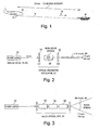
Figure 1 is a diagrammatic illustration of a tactical situation in which an airborne laser target designator produces a single pulse for illuminating a target at a substantial distance in which the laser is an eye safe laser operating in the 1.5µm (micron) region of the electromagnetic spectrum; -
Figure 2 is a block diagram of a prior art laser for use in a laser target designating system in which an optical parametric oscillator utilizes a non-linear crystal such as KTP pumped by a 1µm (micron) pumping laser to produce a 60mJ output having a beam divergence less than 1.2mrad (milliradian) with a 20mm aperture; -
Figure 3 is a block diagram of a proposed multicrystal optical parametric oscillator for increasing the output over the system depicted inFigure 2 but resulting in an unacceptable beam spread; -
Figure 4 is a block diagram of a combined optical parametric oscillator, optical parametric amplifier system in which pumping pulses are split apart, with one pumping pulse used to pump the optical parametric oscillator and with the other pumping pulse delayed and used to pump the optical parametric amplifier, illustrating the number of optical elements used; -
Figure 5A, 5B, and 5C are graphs showing the generation of pumping pulses and the resultant output from respectively the optical parametric oscillator and optical parametric amplifier ofFigure 4 , indicating the delay necessary in the pumping pulse to the optical parametric amplifier; -
Figure 6 is a block diagram of the subject combined optical parametric oscillator and optical parametric amplifier located in a single beam line in which the optical parametric oscillator is pumped with the output from a pump laser, the output of which is utilized to pump the optical parametric amplifier without the requirement of synchronization, thus to produce a 150mJ output at 1.5µm (micron) with a less than 1.2mrad (milliradian) beam divergence when using a 20mm aperture, with half of the power from the optical parametric oscillator and with the other half of the power from the optical parametric amplifier; and, -
Figure 7 is a pair of graphs showing the pumping pulse for the optical parametric oscillator and the reduced power of the optical parametric amplifier pumping pulse, with the original pumping pulse being reduced by the amount of energy converted by the optical parametric oscillator to produce its 75mJ output which is coupled to the optical parametric amplifier. - Referring now to
Figure 1 , for eye safe laser target designation or target illumination, in an airborne application anaircraft 10 is provided with alaser target designator 12 which provides abeam 14 directed to atarget 16 in which the target is illuminated by asingle pulse 18. - It will be appreciated that it is important to provide an eye safe laser for such laser target designation or illumination due to the fact that human beings may be in the area and if the radiation impinges upon the eye of a human being, damage can occur unless the radiation is in the 1.5µm (micron) range.
- For long distance eye safe laser ranging and illumination, for instance up to and exceeding 25km, it is only with difficulty that one can provide sufficient power on target to operate at such long ranges.
- Referring to
Figure 2 , as has been attempted, apump laser 20 has been utilized to pump an opticalparametric oscillator 22 having aninput mirror 24 and anoutput mirror 26 into which is disposed anon-linear crystal 28 usually of KTP. The result is aoutput beam 30 having an output power of 60mJ and a beam divergence of less than 1.2mrad (milliradian) with a 20mm aperture, clearly usable for close in laser target designation and illumination applications, but not enough power for robust long range work. - Note that beam divergence depends on aperture size. When one multiplies the aperture size with beam divergence, one gets a beam quality characteristic measured in terms of mm-milliradians. Thus for a 20mm clear aperture and a 1.2mrad (milliradian) beam spread, one has a beam quality of 24mm.mrad (mm.milliradians).
- In typical military designator/range finder laser transmitters, the KTP optical parametric oscillator is pumped using the 300mJ to 400mJ output from the 1.06µm designator laser. In one embodiment, the pumping laser is a diode-pumped, conduction cooled, Nd:YAG zig-zag slab oscillator-amplifier which produces 300mJ at 1064nm with a pulse repetition frequency of 20Hz (hertz), and with each of the pulses being 15ns (nanoseconds) in duration.
- As mentioned hereinbefore, 60mJ is insufficient for long range operation. In an effort to increase the laser output, the pumping laser was used to pump a multi-crystal optical
parametric oscillator 32 having threeKTP crystals output beam 40 did indeed deliver the 150mJ. However, the output beam had significant divergence or beam spread measured at one point at 80mrad (milliradians) for a 20mm aperture. It will be appreciated that such a widely diverging beam has no ready application for long range laser target designators or laser target illuminators. - In an effort to minimize beam spread, referring now to
Figure 4 , a combined optical parametric oscillator and optical parametric amplifier was designed in which pumplaser 20 had its output divided bybeam splitting mirror 42 into two pumping pulses P1 along path 44 and P2 alongpath 46. The first pumping pulse was delivered to opticalparametric oscillator 22 identical to that ofFigure 2 , the output of which online 46 was passed through abeam splitting mirror 48 to an opticalparametric amplifier 50 having twoadditional crystals non-linear crystal 28. - The second pumping pulse, P2, was to be passed through an optical pulse timing delay unit 60 which was to be redirected by a
mirror 62 tobeam splitting mirror 48 where the delayed pumping pulse was injected into opticalparametric amplifier 50. - However, the timing, synchronization and duration of these two pulses is critical in the generation of the higher amplitude output. Referring to
Figure 5A , the pumpingpulse 61 is illustrated as having awaveform 63 with a peak at point P1 and a temporal duration of ΔTP1. This pumping pulse is split atmirror 42 into pulses 65 and 67, respectively, P2 and P3, which only reduces the peak amplitude but does not alter the waveform shape or temporal duration. Note that ΔTP1=ΔTP2=ΔTP3. - Referring to
Figure 5B , pumping pulse P2 is directed into the OPO, which generates anOPO signal output 69. The generated OPO signal waveform is of shorter duration than the pumping pulse due to the non-linear nature of the device. Note that a portion of the pump pulse is needed to achieve threshold, ΔTthresh, in the device and once that threshold is exceeded the OPO signal is rapidly extracted. - Referring to
Figure 5C , an optical delay 67 is introduced for P3 to insure P3 arrives at the OPA at the beginning 71 of the OPO signal, and increases the peak OPO signal. This addresses the fact that there is a delay between the time that the OPO lasers and when the OPO needs to be pumped when using the dual pulse pumping system. - As can be seen from
Figures 5A, 5B, and 5C , there are significant synchronization issues introduced due to the fact that the optimal pumping pulse for the optical parametric amplifier must be delayed with respect with respect to the optimal pumping pulse for the optical parametric oscillator. Moreover, for the delayed pulse pumping there are at least five additional optical elements, namely the four mirrors involved in the pump pulse beam splitting and the optical pulse timing delay unit 60. Not only are the parts count increased, but alignment problems are exacerbated in terms of the mirrors involved. Moreover, the laser target designator/illuminator ofFigure 4 is not at all compact as there has to be significant space allotted for the separation of the two pumping pulses and the pumping pulse timing delay unit. - Referring now to
Figure 6 , in one embodiment of the subject invention two pumping pulses are avoided. Rather a single pumping pulse is first delivered to the oscillator with enough of the pumping pulse left over from the output of the oscillator to pump the amplifier. Moreover, since the left over pumping pulse comes out of the oscillator with the 1.5µm (micron) signal output, it arrives at exactly the right time to pump the amplifier, just as the amplifier is receiving the output of the oscillator. - To illustrate this, in
Figure 6 a pumpinglaser 80 has itsoutput 82 directed though aninput mirror 84 into a singly resonant oscillator having acrystal 86 interposed betweeninput mirror 84 andoutput mirror 88. The combination ofinput mirror 84,crystal 86 andoutput mirror 88 constitutes opticalparametric oscillator 90 as illustrated. - In one embodiment, the pumping laser is a diode laser producing a 300mJ output at 1.0µm (micron), with the
non-linear crystal 86 being a KTP crystal. When this crystal is pumped with 1.0µm (micron) energy, its response is an output at 1.5µm (micron) as well as 3.3µm (microns). However, coatings onmirrors parametric oscillator 90 produces a 75mJ output at 1.5µm (microns) coupled into an opticalparametric amplifier 92 composed ofnon-linear crystals - Thus it will be seen that the optical parametric amplifier is seeded with 75mJ at 1.5µm (micron) as well as a pumping pulse of 225mJ of 1.0µm (micron) energy.
- It has been found that the output from the optical parametric amplifier is 150mJ at 1.5µm (micron) with a beam divergence less than 1.2mrad (milliradian) assuming a 20mm aperture.
- What will be appreciated is that there need be no specialized synchronization for the pumping pulses for the optical parametric oscillator and the optical parametric amplifier. The delay of the 225mJ pumping pulse caused by the pumping of the optical parametric oscillator is exactly such as to provide the appropriate timing for the pumping pulse for the optical parametric amplifier. The result also is a 15ns (nanoseconds)
pulse 98 useful for long range eye safe single pulse target illumination and designation. - Referring to
Figure 7 , it will be appreciated that the pumping pulse for the optical parametric oscillator is at 300mJ and 1.0µm (micron) as illustrated bywaveform 100, whereas thepumping pulse 102 for the optical parametric amplifier is at 225mJ at 1.0µm (micron), with this waveform being slightly flattened due to the fact of its having passed through the optical parametric oscillator. - As will be seen, one has therefore taken the Nd:YAG pumped KTP optical parametric oscillator of the prior art and amplified its output from 60mJ to 150mJ at greater than 35% efficiency with less than 1.2mrad (milliradians) beam divergence using in one embodiment the existing telescope magnification of 3.8 and a clear aperture 20mm (millimetres) combination. In this embodiment, the prior diode pump Nd:YAG laser was configured as an oscillator amplifier using identical side diode pumped conduction cooled zig-zag slabs. The details of such a pump laser have been described in " Multifunction Laser Radar" J. A. Hutchinson, C. W. Trussell, S. J. Hamlin, T. H. Allik, J. C. McCarthy and M. S. Bowers, Laser Radar Technology and Applications IV, Gary W. Kamerman, Christian Werner, Editors, Proceedings of SPIE, Vol. 3707, pumping pulse, 222-233 (1999). Note that in one embodiment, the pump laser pulse width is 18ns (nanoseconds) in one embodiment operating at 9mrad (milliradians) for repetition rates between 10 and 20Hz.
- Note that in the subject application the pumping laser has a simple 1064nm (nanometers) pumped non-critically phased matched KTP OPO-OPA architecture, with the optical parametric oscillator having an unstable resonator of magnification 1.2 as described in " Improved OPO Brightness with a GRM Non-confocal Unstable Resonator", S. Chandra, T. H. Allik, J. A. Hutchinson, and M. S. Bowers, "OSA Trends in Optics and Photonics on Advanced Solid State Lasers", Stephen A. Payne and Clifford R. Pollock (Optical Society of America, Washington, D. C., 1996), Vol. 1, 177-178, with both generated signal and residual pump directly pumping dual 20 millimeter length KTP OPA's. The pump beam spot size input to the optical parametric oscillator was approximate; 4 x 4 millimeters providing a 110MW/cm2 of drive.
- Ideally the optical parametric oscillator threshold is set to provide approximately half the total OPO-OPA output. A low optical parametric oscillator threshold will couple too efficiently to high order oscillator modes and degrade the beam quality, while a high optical parametric oscillator threshold will force the amplified parametric florescence to dominate, also with poor beam quality.
- It is noted that while the subject invention has been described in connection with eye safe lasers, the same techniques can be used at other wavelengths. The subject technique is thus usable at other wavelengths with the criteria that the non-linear converter is preferably non-critically phase matched, meaning that is has reduced alignment sensitivity. Whether or not non-critically phase matched, in one embodiment the subject system is usable in the mid infrared using an OPO-OPA combination involving zinc germanium phosphide crystals, with the laser being angle tunable between 3-5µm (microns) and using a 2µm (microns) pump laser.
- Having now described a few embodiments of the invention, and some modifications and variations thereto, it should be apparent to those skilled in the art that the foregoing is merely illustrative and not limiting, having been presented by the way of example only. Numerous modifications and other embodiments are within the scope of one skilled in the art and are contemplated as falling within the scope of the invention as limited only by the appended claims and equivalents thereto.
Claims (11)
- An eye safe laser comprising:- a pumping source (80) arranged to produce pumping pulses (82) at a first wavelength;- an optical parametric oscillator (90) coupled to said pumping source (80) arranged to receive pumping pulses at said first wavelength and arranged to generate an output at a second wavelength; and- an optical parametric amplifier (92) coupled to said optical parametric oscillator (90) arranger to amplify said output at said second wavelength utilizing said pumping pulses from said pumping source (80), said oscillator (90), amplifier (92) and pumping source (80) being all located on a single beam line.
- A laser according to Claim 1, wherein said pumping source (80) outputs 1.0µm pumping pulses (82) at a given energy level.
- A laser according to Claim 2, wherein said pumping pulses (82) pump said optical parametric oscillator (90) to produce said output at said second wavelength at a first energy level less than said given energy level.
- A laser according to Claim 2 or 3, wherein said second wavelength is 1.5µm.
- A laser according to Claim 4, wherein said optical parametric oscillator (90) has a cavity delimited by input and output mirrors (84, 86), said mirrors being coated so that 1.5µm radiation is outputted together with said pumping pulses (82) at a second energy level.
- A laser according to any one of Claims 2 to 4, wherein said pulses have a pulse duration in excess of 15ns.
- A laser according to any one of the preceding Claims, wherein said oscillator (90) and said amplifier (92) each include at least one non-linear crystal.
- A laser according to Claim 7, wherein said crystals include KTP crystals.
- A laser according to Claim 8, wherein said pumping source (80) includes a Nd:YAG laser.
- A laser according to any one of the preceding Claims, wherein said laser produces a beam having a beam quality characteristic measured in terms of mm.mrad of 24 mm.mrad.
- A method of operating an eye safe laser including a pumping source (80), an optical parametric oscillator (90), and an optical parametric amplifier (92), all located on a single beam line, the method comprising the steps of:(a) producing pumping pulses (82) at a first wavelength using said pumping source (80);(b) generating an output at a second wavelength using said optical parametric oscillator (90);(c) amplifying said output at a second wavelength using said optical parametric amplifier (92); and(d) pumping both said optical parametric oscillator (90) and amplifier (92) with said pumping pulses (82) from said pumping source (80).
Applications Claiming Priority (5)
| Application Number | Priority Date | Filing Date | Title |
|---|---|---|---|
| US39095202P | 2002-06-24 | 2002-06-24 | |
| US390952P | 2002-06-24 | ||
| US424300 | 2003-04-28 | ||
| US10/424,300 US6898218B2 (en) | 2002-06-24 | 2003-04-28 | Method and apparatus for increasing the intensity of an eye safe laser |
| PCT/US2003/019934 WO2004000163A2 (en) | 2002-06-24 | 2003-06-24 | Method and apparatus for increasing the intensity of an eye safe laser |
Publications (3)
| Publication Number | Publication Date |
|---|---|
| EP1530744A2 EP1530744A2 (en) | 2005-05-18 |
| EP1530744A4 EP1530744A4 (en) | 2005-09-14 |
| EP1530744B1 true EP1530744B1 (en) | 2009-04-01 |
Family
ID=30003177
Family Applications (1)
| Application Number | Title | Priority Date | Filing Date |
|---|---|---|---|
| EP03751781A Expired - Lifetime EP1530744B1 (en) | 2002-06-24 | 2003-06-24 | Method and apparatus for increasing the intensity of an eye safe laser |
Country Status (6)
| Country | Link |
|---|---|
| US (1) | US6898218B2 (en) |
| EP (1) | EP1530744B1 (en) |
| AT (1) | ATE427518T1 (en) |
| AU (1) | AU2003269894A1 (en) |
| DE (1) | DE60326960D1 (en) |
| WO (1) | WO2004000163A2 (en) |
Cited By (1)
| Publication number | Priority date | Publication date | Assignee | Title |
|---|---|---|---|---|
| US11349276B1 (en) | 2020-12-02 | 2022-05-31 | Bae Systems Information And Electronic Systems Integration Inc. | Ultra-short pulse mid and long wave infrared laser |
Families Citing this family (21)
| Publication number | Priority date | Publication date | Assignee | Title |
|---|---|---|---|---|
| US7916388B2 (en) * | 2007-12-20 | 2011-03-29 | Cymer, Inc. | Drive laser for EUV light source |
| US6870664B2 (en) * | 2001-12-13 | 2005-03-22 | The Regents Of The University Of California | Nondegenerate optical parametric chirped pulse amplifier |
| US6965621B2 (en) * | 2003-10-28 | 2005-11-15 | Bae Systems Information And Electronic Systems Integration Inc. | Ring optical parametric oscillator/optical parametric amplifier combination in single beamline |
| US8040929B2 (en) | 2004-03-25 | 2011-10-18 | Imra America, Inc. | Optical parametric amplification, optical parametric generation, and optical pumping in optical fibers systems |
| US7751462B2 (en) * | 2007-03-14 | 2010-07-06 | The United States Of America As Represented By The Secretary Of The Army | Mono-slab laser cavity |
| US7714989B1 (en) | 2007-11-28 | 2010-05-11 | The United States Of America As Represented By The Secretary Of The Navy | Micropulse laser guidance |
| US8023538B2 (en) | 2008-03-27 | 2011-09-20 | Imra America, Inc. | Ultra-high power parametric amplifier system at high repetition rates |
| US20120020378A1 (en) * | 2010-07-21 | 2012-01-26 | Li Steven X | Widely tunable optical parametric generator having narrow bandwidth field |
| WO2012092362A2 (en) * | 2010-12-30 | 2012-07-05 | Lockheed Martin Corporation | Optically locked high energy opo-opa |
| US9823351B2 (en) | 2012-12-18 | 2017-11-21 | Uber Technologies, Inc. | Multi-clad fiber based optical apparatus and methods for light detection and ranging sensors |
| US9470520B2 (en) | 2013-03-14 | 2016-10-18 | Apparate International C.V. | LiDAR scanner |
| CA2931055C (en) | 2013-11-22 | 2022-07-12 | Ottomotto Llc | Lidar scanner calibration |
| CN105281191B (en) * | 2015-11-18 | 2018-01-26 | 浙江大学 | A kind of device and method for producing high efficiency narrow linewidth mid-infrared laser |
| CN106898942A (en) * | 2017-02-28 | 2017-06-27 | 中国科学院光电研究院 | The adjusting method of multi beam pulse phototiming |
| US10756505B2 (en) | 2017-09-21 | 2020-08-25 | Qioptiq Photonics Gmbh & Co. Kg | Tunable light source with broadband output |
| US10409139B2 (en) | 2017-09-21 | 2019-09-10 | Qioptiq Photonics Gmbh & Co. Kg | Light source with multi-longitudinal mode continuous wave output based on multi-mode resonant OPO technology |
| EP3857656B1 (en) * | 2018-09-27 | 2023-11-15 | Iridesense | A laser device for laser detection and ranging (lidar) |
| US11754681B2 (en) * | 2019-04-04 | 2023-09-12 | Aeva, Inc. | LIDAR system with a multi-mode waveguide photodetector |
| CN111146672B (en) * | 2019-12-30 | 2021-03-23 | 哈尔滨工业大学 | Narrow-linewidth 3-5 μm medium-wave infrared solid laser |
| CN115117721A (en) * | 2022-06-28 | 2022-09-27 | 中国科学院上海光学精密机械研究所 | Narrow linewidth multi-wavelength nanosecond single-frequency pulse laser |
| CN115832845A (en) * | 2022-11-08 | 2023-03-21 | 中国科学院上海光学精密机械研究所 | Large-energy nanosecond pulse optical parameter amplification system |
Family Cites Families (7)
| Publication number | Priority date | Publication date | Assignee | Title |
|---|---|---|---|---|
| US5181211A (en) * | 1991-05-20 | 1993-01-19 | Fibertek, Inc. | Eye-safe laser system |
| US5606453A (en) * | 1993-04-20 | 1997-02-25 | Light Age, Inc. | Optical parametric amplifiers and oscillators pumped by tunable laser sources |
| US5400173A (en) * | 1994-01-14 | 1995-03-21 | Northrop Grumman Corporation | Tunable mid-infrared wavelength converter using cascaded parametric oscillators |
| US5577058A (en) * | 1994-09-13 | 1996-11-19 | Spectra-Physics Lasers, Inc. | Broadly tunable single longitudinal mode output produced from multi longitudinal mode seed source |
| DE19619483A1 (en) * | 1996-05-14 | 1997-11-20 | Lambda Physik Gmbh | Tunable narrowband source of coherent radiation |
| US6359914B1 (en) * | 1999-10-04 | 2002-03-19 | University Of Dayton | Tunable pulsed narrow bandwidth light source |
| EP1207387A1 (en) * | 2000-11-20 | 2002-05-22 | Institut Curie | Multi-photon imaging installation. |
-
2003
- 2003-04-28 US US10/424,300 patent/US6898218B2/en not_active Expired - Lifetime
- 2003-06-24 WO PCT/US2003/019934 patent/WO2004000163A2/en not_active Ceased
- 2003-06-24 EP EP03751781A patent/EP1530744B1/en not_active Expired - Lifetime
- 2003-06-24 AT AT03751781T patent/ATE427518T1/en not_active IP Right Cessation
- 2003-06-24 DE DE60326960T patent/DE60326960D1/en not_active Expired - Lifetime
- 2003-06-24 AU AU2003269894A patent/AU2003269894A1/en not_active Abandoned
Cited By (1)
| Publication number | Priority date | Publication date | Assignee | Title |
|---|---|---|---|---|
| US11349276B1 (en) | 2020-12-02 | 2022-05-31 | Bae Systems Information And Electronic Systems Integration Inc. | Ultra-short pulse mid and long wave infrared laser |
Also Published As
| Publication number | Publication date |
|---|---|
| EP1530744A4 (en) | 2005-09-14 |
| WO2004000163A3 (en) | 2005-02-10 |
| WO2004000163A2 (en) | 2003-12-31 |
| ATE427518T1 (en) | 2009-04-15 |
| AU2003269894A1 (en) | 2004-01-06 |
| US6898218B2 (en) | 2005-05-24 |
| AU2003269894A8 (en) | 2004-01-06 |
| DE60326960D1 (en) | 2009-05-14 |
| EP1530744A2 (en) | 2005-05-18 |
| US20040012841A1 (en) | 2004-01-22 |
Similar Documents
| Publication | Publication Date | Title |
|---|---|---|
| US6898218B2 (en) | Method and apparatus for increasing the intensity of an eye safe laser | |
| US5434662A (en) | Speckle resistant method and apparatus with chirped laser beam | |
| EP0009108B1 (en) | An improved laser having a nonlinear phase conjugating reflector | |
| US5659419A (en) | Tunable narrowband optical parametrical oscillator | |
| US9136667B2 (en) | High peak power optical amplifier | |
| EP0795855A3 (en) | Optical pickup apparatus | |
| EP2026124A1 (en) | Wide-band vhf-pulse light oscillator utilizing chirp pulse amplification | |
| US5383198A (en) | Self-starting mode-locked ring cavity laser | |
| ATE369641T1 (en) | TUNABLE HIGH POWER LASER | |
| EP3360209B1 (en) | Sub-nanosecond broad spectrum generating laser system | |
| US20020048078A1 (en) | Short pulse optical parametric oscillator system | |
| US5721748A (en) | Intracavity doubled solid state Raman laser system | |
| US7999228B2 (en) | Apparatus for use in operator training with, and the testing and evaluation of, infrared sensors which are for missile detection | |
| US20130195128A1 (en) | Multiple Wavelength Laser System | |
| US5751472A (en) | Multi-pass optical parametric generator | |
| US4852107A (en) | Laser resonator with changable frequency of radiation | |
| US6005878A (en) | Efficient frequency conversion apparatus for use with multimode solid-state lasers | |
| TW324866B (en) | Compact laser apparatus and method | |
| US5144629A (en) | Method and apparatus for laser tuning | |
| US5917843A (en) | Laser cavity assembly | |
| GB2306828A (en) | Covert 3-dimensional imaging lidar | |
| JPH0350879A (en) | Phase conjugate laser with temporary square pulse | |
| US5241551A (en) | High average power laser which generates radiation at a wavelength near 530 nm | |
| WO2025090160A2 (en) | Methods of generating laser outputs based on different states of laser inputs and related systems | |
| US4992750A (en) | Coupling mechanism for efficient conversion of axisymmetric beam profiles into profiles suitable for diffraction |
Legal Events
| Date | Code | Title | Description |
|---|---|---|---|
| PUAI | Public reference made under article 153(3) epc to a published international application that has entered the european phase |
Free format text: ORIGINAL CODE: 0009012 |
|
| 17P | Request for examination filed |
Effective date: 20041223 |
|
| AK | Designated contracting states |
Kind code of ref document: A2 Designated state(s): AT BE BG CH CY CZ DE DK EE ES FI FR GB GR HU IE IT LI LU MC NL PT RO SE SI SK TR |
|
| AX | Request for extension of the european patent |
Extension state: AL LT LV MK |
|
| A4 | Supplementary search report drawn up and despatched |
Effective date: 20050803 |
|
| RIC1 | Information provided on ipc code assigned before grant |
Ipc: 7G 02F 1/35 A Ipc: 7H 01S 3/10 B |
|
| DAX | Request for extension of the european patent (deleted) | ||
| GRAP | Despatch of communication of intention to grant a patent |
Free format text: ORIGINAL CODE: EPIDOSNIGR1 |
|
| GRAS | Grant fee paid |
Free format text: ORIGINAL CODE: EPIDOSNIGR3 |
|
| GRAA | (expected) grant |
Free format text: ORIGINAL CODE: 0009210 |
|
| AK | Designated contracting states |
Kind code of ref document: B1 Designated state(s): AT BE BG CH CY CZ DE DK EE ES FI FR GB GR HU IE IT LI LU MC NL PT RO SE SI SK TR |
|
| REG | Reference to a national code |
Ref country code: GB Ref legal event code: FG4D |
|
| REG | Reference to a national code |
Ref country code: CH Ref legal event code: EP |
|
| REG | Reference to a national code |
Ref country code: IE Ref legal event code: FG4D |
|
| REF | Corresponds to: |
Ref document number: 60326960 Country of ref document: DE Date of ref document: 20090514 Kind code of ref document: P |
|
| PG25 | Lapsed in a contracting state [announced via postgrant information from national office to epo] |
Ref country code: SI Free format text: LAPSE BECAUSE OF FAILURE TO SUBMIT A TRANSLATION OF THE DESCRIPTION OR TO PAY THE FEE WITHIN THE PRESCRIBED TIME-LIMIT Effective date: 20090401 |
|
| NLV1 | Nl: lapsed or annulled due to failure to fulfill the requirements of art. 29p and 29m of the patents act | ||
| PG25 | Lapsed in a contracting state [announced via postgrant information from national office to epo] |
Ref country code: ES Free format text: LAPSE BECAUSE OF FAILURE TO SUBMIT A TRANSLATION OF THE DESCRIPTION OR TO PAY THE FEE WITHIN THE PRESCRIBED TIME-LIMIT Effective date: 20090712 Ref country code: PT Free format text: LAPSE BECAUSE OF FAILURE TO SUBMIT A TRANSLATION OF THE DESCRIPTION OR TO PAY THE FEE WITHIN THE PRESCRIBED TIME-LIMIT Effective date: 20090902 Ref country code: EE Free format text: LAPSE BECAUSE OF FAILURE TO SUBMIT A TRANSLATION OF THE DESCRIPTION OR TO PAY THE FEE WITHIN THE PRESCRIBED TIME-LIMIT Effective date: 20090401 Ref country code: AT Free format text: LAPSE BECAUSE OF FAILURE TO SUBMIT A TRANSLATION OF THE DESCRIPTION OR TO PAY THE FEE WITHIN THE PRESCRIBED TIME-LIMIT Effective date: 20090401 Ref country code: FI Free format text: LAPSE BECAUSE OF FAILURE TO SUBMIT A TRANSLATION OF THE DESCRIPTION OR TO PAY THE FEE WITHIN THE PRESCRIBED TIME-LIMIT Effective date: 20090401 |
|
| PG25 | Lapsed in a contracting state [announced via postgrant information from national office to epo] |
Ref country code: NL Free format text: LAPSE BECAUSE OF FAILURE TO SUBMIT A TRANSLATION OF THE DESCRIPTION OR TO PAY THE FEE WITHIN THE PRESCRIBED TIME-LIMIT Effective date: 20090401 Ref country code: SE Free format text: LAPSE BECAUSE OF FAILURE TO SUBMIT A TRANSLATION OF THE DESCRIPTION OR TO PAY THE FEE WITHIN THE PRESCRIBED TIME-LIMIT Effective date: 20090701 |
|
| PG25 | Lapsed in a contracting state [announced via postgrant information from national office to epo] |
Ref country code: RO Free format text: LAPSE BECAUSE OF FAILURE TO SUBMIT A TRANSLATION OF THE DESCRIPTION OR TO PAY THE FEE WITHIN THE PRESCRIBED TIME-LIMIT Effective date: 20090401 Ref country code: DK Free format text: LAPSE BECAUSE OF FAILURE TO SUBMIT A TRANSLATION OF THE DESCRIPTION OR TO PAY THE FEE WITHIN THE PRESCRIBED TIME-LIMIT Effective date: 20090401 Ref country code: MC Free format text: LAPSE BECAUSE OF NON-PAYMENT OF DUE FEES Effective date: 20090630 Ref country code: CZ Free format text: LAPSE BECAUSE OF FAILURE TO SUBMIT A TRANSLATION OF THE DESCRIPTION OR TO PAY THE FEE WITHIN THE PRESCRIBED TIME-LIMIT Effective date: 20090401 |
|
| REG | Reference to a national code |
Ref country code: CH Ref legal event code: PL |
|
| PLBE | No opposition filed within time limit |
Free format text: ORIGINAL CODE: 0009261 |
|
| STAA | Information on the status of an ep patent application or granted ep patent |
Free format text: STATUS: NO OPPOSITION FILED WITHIN TIME LIMIT |
|
| PG25 | Lapsed in a contracting state [announced via postgrant information from national office to epo] |
Ref country code: BE Free format text: LAPSE BECAUSE OF FAILURE TO SUBMIT A TRANSLATION OF THE DESCRIPTION OR TO PAY THE FEE WITHIN THE PRESCRIBED TIME-LIMIT Effective date: 20090401 Ref country code: SK Free format text: LAPSE BECAUSE OF FAILURE TO SUBMIT A TRANSLATION OF THE DESCRIPTION OR TO PAY THE FEE WITHIN THE PRESCRIBED TIME-LIMIT Effective date: 20090401 |
|
| 26N | No opposition filed |
Effective date: 20100105 |
|
| PG25 | Lapsed in a contracting state [announced via postgrant information from national office to epo] |
Ref country code: BG Free format text: LAPSE BECAUSE OF FAILURE TO SUBMIT A TRANSLATION OF THE DESCRIPTION OR TO PAY THE FEE WITHIN THE PRESCRIBED TIME-LIMIT Effective date: 20090701 |
|
| PG25 | Lapsed in a contracting state [announced via postgrant information from national office to epo] |
Ref country code: LI Free format text: LAPSE BECAUSE OF NON-PAYMENT OF DUE FEES Effective date: 20090630 Ref country code: CH Free format text: LAPSE BECAUSE OF NON-PAYMENT OF DUE FEES Effective date: 20090630 Ref country code: IE Free format text: LAPSE BECAUSE OF NON-PAYMENT OF DUE FEES Effective date: 20090624 |
|
| PG25 | Lapsed in a contracting state [announced via postgrant information from national office to epo] |
Ref country code: GR Free format text: LAPSE BECAUSE OF FAILURE TO SUBMIT A TRANSLATION OF THE DESCRIPTION OR TO PAY THE FEE WITHIN THE PRESCRIBED TIME-LIMIT Effective date: 20090702 |
|
| PG25 | Lapsed in a contracting state [announced via postgrant information from national office to epo] |
Ref country code: IT Free format text: LAPSE BECAUSE OF FAILURE TO SUBMIT A TRANSLATION OF THE DESCRIPTION OR TO PAY THE FEE WITHIN THE PRESCRIBED TIME-LIMIT Effective date: 20090401 |
|
| PG25 | Lapsed in a contracting state [announced via postgrant information from national office to epo] |
Ref country code: LU Free format text: LAPSE BECAUSE OF NON-PAYMENT OF DUE FEES Effective date: 20090624 |
|
| PG25 | Lapsed in a contracting state [announced via postgrant information from national office to epo] |
Ref country code: HU Free format text: LAPSE BECAUSE OF FAILURE TO SUBMIT A TRANSLATION OF THE DESCRIPTION OR TO PAY THE FEE WITHIN THE PRESCRIBED TIME-LIMIT Effective date: 20091002 |
|
| PG25 | Lapsed in a contracting state [announced via postgrant information from national office to epo] |
Ref country code: TR Free format text: LAPSE BECAUSE OF FAILURE TO SUBMIT A TRANSLATION OF THE DESCRIPTION OR TO PAY THE FEE WITHIN THE PRESCRIBED TIME-LIMIT Effective date: 20090401 |
|
| PG25 | Lapsed in a contracting state [announced via postgrant information from national office to epo] |
Ref country code: CY Free format text: LAPSE BECAUSE OF FAILURE TO SUBMIT A TRANSLATION OF THE DESCRIPTION OR TO PAY THE FEE WITHIN THE PRESCRIBED TIME-LIMIT Effective date: 20090401 |
|
| REG | Reference to a national code |
Ref country code: FR Ref legal event code: TP Owner name: SCHILMASS CO LLC, US Effective date: 20120315 |
|
| REG | Reference to a national code |
Ref country code: DE Ref legal event code: R081 Ref document number: 60326960 Country of ref document: DE Owner name: SCHILMASS CO. L.L.C., US Free format text: FORMER OWNER: BAE SYSTEMS INFORMATION AND ELECTRONIC SYSTEMS INTEGRATION INC., NASHUA, US Effective date: 20120319 |
|
| REG | Reference to a national code |
Ref country code: GB Ref legal event code: 732E Free format text: REGISTERED BETWEEN 20120419 AND 20120425 |
|
| PGFP | Annual fee paid to national office [announced via postgrant information from national office to epo] |
Ref country code: DE Payment date: 20120629 Year of fee payment: 10 |
|
| REG | Reference to a national code |
Ref country code: DE Ref legal event code: R119 Ref document number: 60326960 Country of ref document: DE Effective date: 20140101 |
|
| PG25 | Lapsed in a contracting state [announced via postgrant information from national office to epo] |
Ref country code: DE Free format text: LAPSE BECAUSE OF NON-PAYMENT OF DUE FEES Effective date: 20140101 |
|
| PGFP | Annual fee paid to national office [announced via postgrant information from national office to epo] |
Ref country code: GB Payment date: 20140527 Year of fee payment: 12 |
|
| PGFP | Annual fee paid to national office [announced via postgrant information from national office to epo] |
Ref country code: FR Payment date: 20140527 Year of fee payment: 12 |
|
| GBPC | Gb: european patent ceased through non-payment of renewal fee |
Effective date: 20150624 |
|
| REG | Reference to a national code |
Ref country code: FR Ref legal event code: ST Effective date: 20160229 |
|
| PG25 | Lapsed in a contracting state [announced via postgrant information from national office to epo] |
Ref country code: GB Free format text: LAPSE BECAUSE OF NON-PAYMENT OF DUE FEES Effective date: 20150624 |
|
| PG25 | Lapsed in a contracting state [announced via postgrant information from national office to epo] |
Ref country code: FR Free format text: LAPSE BECAUSE OF NON-PAYMENT OF DUE FEES Effective date: 20150630 |