EP1530259A1 - Improvement to source antennas with radiating aperture - Google Patents
Improvement to source antennas with radiating aperture Download PDFInfo
- Publication number
- EP1530259A1 EP1530259A1 EP04104946A EP04104946A EP1530259A1 EP 1530259 A1 EP1530259 A1 EP 1530259A1 EP 04104946 A EP04104946 A EP 04104946A EP 04104946 A EP04104946 A EP 04104946A EP 1530259 A1 EP1530259 A1 EP 1530259A1
- Authority
- EP
- European Patent Office
- Prior art keywords
- insert
- horn
- aperture
- source antenna
- antenna according
- Prior art date
- Legal status (The legal status is an assumption and is not a legal conclusion. Google has not performed a legal analysis and makes no representation as to the accuracy of the status listed.)
- Withdrawn
Links
- 230000006872 improvement Effects 0.000 title description 3
- 239000003989 dielectric material Substances 0.000 claims abstract description 7
- 238000007667 floating Methods 0.000 claims abstract description 3
- 239000006260 foam Substances 0.000 claims description 12
- 230000005855 radiation Effects 0.000 claims description 10
- 230000001747 exhibiting effect Effects 0.000 claims description 8
- 229920002994 synthetic fiber Polymers 0.000 claims description 5
- 238000012937 correction Methods 0.000 claims description 2
- 230000004044 response Effects 0.000 description 12
- 238000009826 distribution Methods 0.000 description 6
- 239000000463 material Substances 0.000 description 5
- 238000001465 metallisation Methods 0.000 description 5
- 238000003780 insertion Methods 0.000 description 3
- 230000037431 insertion Effects 0.000 description 3
- 230000010363 phase shift Effects 0.000 description 3
- 238000004891 communication Methods 0.000 description 2
- 238000004088 simulation Methods 0.000 description 2
- 230000004075 alteration Effects 0.000 description 1
- 230000005540 biological transmission Effects 0.000 description 1
- 238000013461 design Methods 0.000 description 1
- 238000006073 displacement reaction Methods 0.000 description 1
- 230000005684 electric field Effects 0.000 description 1
- 230000005672 electromagnetic field Effects 0.000 description 1
- 238000013012 foaming technology Methods 0.000 description 1
- 238000005286 illumination Methods 0.000 description 1
- 238000004519 manufacturing process Methods 0.000 description 1
- 238000000034 method Methods 0.000 description 1
- 230000003287 optical effect Effects 0.000 description 1
- 230000010287 polarization Effects 0.000 description 1
- 230000009467 reduction Effects 0.000 description 1
- 239000007787 solid Substances 0.000 description 1
Images




Classifications
-
- H—ELECTRICITY
- H01—ELECTRIC ELEMENTS
- H01Q—ANTENNAS, i.e. RADIO AERIALS
- H01Q13/00—Waveguide horns or mouths; Slot antennas; Leaky-waveguide antennas; Equivalent structures causing radiation along the transmission path of a guided wave
- H01Q13/02—Waveguide horns
- H01Q13/0283—Apparatus or processes specially provided for manufacturing horns
-
- H—ELECTRICITY
- H01—ELECTRIC ELEMENTS
- H01Q—ANTENNAS, i.e. RADIO AERIALS
- H01Q13/00—Waveguide horns or mouths; Slot antennas; Leaky-waveguide antennas; Equivalent structures causing radiation along the transmission path of a guided wave
- H01Q13/02—Waveguide horns
- H01Q13/0208—Corrugated horns
- H01Q13/0225—Corrugated horns of non-circular cross-section
-
- H—ELECTRICITY
- H01—ELECTRIC ELEMENTS
- H01Q—ANTENNAS, i.e. RADIO AERIALS
- H01Q19/00—Combinations of primary active antenna elements and units with secondary devices, e.g. with quasi-optical devices, for giving the antenna a desired directional characteristic
- H01Q19/06—Combinations of primary active antenna elements and units with secondary devices, e.g. with quasi-optical devices, for giving the antenna a desired directional characteristic using refracting or diffracting devices, e.g. lens
- H01Q19/08—Combinations of primary active antenna elements and units with secondary devices, e.g. with quasi-optical devices, for giving the antenna a desired directional characteristic using refracting or diffracting devices, e.g. lens for modifying the radiation pattern of a radiating horn in which it is located
-
- H—ELECTRICITY
- H01—ELECTRIC ELEMENTS
- H01Q—ANTENNAS, i.e. RADIO AERIALS
- H01Q19/00—Combinations of primary active antenna elements and units with secondary devices, e.g. with quasi-optical devices, for giving the antenna a desired directional characteristic
- H01Q19/10—Combinations of primary active antenna elements and units with secondary devices, e.g. with quasi-optical devices, for giving the antenna a desired directional characteristic using reflecting surfaces
- H01Q19/12—Combinations of primary active antenna elements and units with secondary devices, e.g. with quasi-optical devices, for giving the antenna a desired directional characteristic using reflecting surfaces wherein the surfaces are concave
- H01Q19/13—Combinations of primary active antenna elements and units with secondary devices, e.g. with quasi-optical devices, for giving the antenna a desired directional characteristic using reflecting surfaces wherein the surfaces are concave the primary radiating source being a single radiating element, e.g. a dipole, a slot, a waveguide termination
- H01Q19/132—Horn reflector antennas; Off-set feeding
Definitions
- the present invention relates to source antennas constituted by a radiating aperture, more particularly by a horn. It also relates to an antenna structure comprising a source antenna in accordance with the invention, associated with a focusing system of the homogeneous lens type.
- the use of a focusing system of the parabola type is not adequate.
- the latter in order to ensure the continuous tracking of nongeostationary satellites over their trajectory and to avoid the interruption of communication when said satellites are no longer in direct line of sight with the ground antenna, the latter must exhibit, at least during the period of switching from one satellite to another, two separate beams.
- the angular coverage of the beams must be ensured over a very wide area.
- a homogeneous lens exhibits a lower manufacturing cost. However, it does not allow perfect focusing of an incident plane wave. Specifically, aberration phenomena are noted at the level of the focal surface. In the case of a homogeneous lens, one no longer speaks of a focal point as in a focusing system constituted by a parabola or a Luneberg lens but of a focal spot, the focusing area being more extended.
- the exit focusing imperfections of a homogeneous lens render the design constraints of the associated primary source antenna more complex.
- the main function of the source antenna associated with the homogeneous lenses is therefore to take into account and to compensate as well as possible for the phase and amplitude distortions introduced by this imperfect focusing system.
- the present invention therefore relates to a source antenna which makes it possible to obtain a distribution of the fields in its radiating aperture and which superimposes as well as possible with that generated by the focusing system.
- the solution conventionally used for the source antenna is a horn.
- the technique generally employed to ensure the symmetrization of the E and H planes consists in the addition of transverse or longitudinal furrows or corrugations inside or outside the horn so as to modify the modal distribution of the electromagnetic fields at the level of the aperture of the horn.
- the corrugations in fact introduce higher hybrid modes into the guided structure at the level of the corrugations, which make it possible to harmonize the phase- and amplitude-response in the aperture of the horn.
- the present invention proposes another solution for the source antenna constituted by a radiating aperture.
- the antenna consists of a source antenna of radiating aperture type inside which is disposed a dielectric insert.
- the use of the dielectric insert makes it possible:
- the radiating aperture is constituted by a horn.
- the horn is formed by a block of foam made of synthetic material whose external surface is metallized, the said block exhibiting an internal recess for receiving the insert.
- the horn is constituted by a block of foam made of synthetic material recessed internally and exhibiting metallized internal and external surfaces.
- the present invention also relates to an antenna structure comprising a source antenna such as described above, associated with a focusing system of the homogeneous lens type.
- the radiating aperture forming the source antenna is constituted by a horn 1 made of a radiating material exhibiting, at one end, a cylindrical shape 1a which flares out progressively up to its aperture 1b.
- an insert 2 made of a dielectric material.
- the materials that may be used are the materials known by the commercial name:
- any dielectric material of permittivity > 1 and with a low enough loss tangent to minimize the dielectric losses may be used, this material possibly being machinable or mouldable.
- the dielectric insert 2 exhibits an elliptical front view.
- the shape of the insert is represented in greater detail in Figure 3.
- the left-hand view of Figure 3 represents the elliptical face of the insert 2 while the right-hand view is a profile view and shows that the insert 2 has a concave shape, according to its longitudinal profile.
- the insert dimensions given in Figure 3 will be used subsequently for simulations.
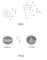
- FIG. 2 gives the phase charts obtained in the aperture of a conventional horn linearly polarized along the axis Ox, respectively in the case where the horn has no insert (left-hand figure), and in the case where the horn has an elliptical dielectric insert (right-hand figure).
- the addition of the elliptical insert makes it possible to symmetrize the phase response in the aperture of the horn. This translates, at the level of the radiation pattern, into a symmetrization in the E and H planes.
- the geometry of the dielectric insert is important for obtaining this symmetrization.
- the elliptical nature of the insert is necessary to ensure the symmetrization of the phase response, the elliptical profile being all the more accentuated the bigger the phase dissymmetry of the horn without insert.
- the longitudinal profile of the slightly concave insert, as illustrated in Figure 3, and the positioning of the insert inside the horn are two parameters that make it possible to adapt, in an optimal manner, the phase- and amplitude-response with respect to the desired response of a given lens.
- the positioning of the insert along the axis Oz greatly influences the amplitude correction, the concave profile allowing it to reduce the phase shift between central and marginal rays.
- This horn exhibits a diameter of 4 cm at the level of the top-centred radiating aperture and the insert exhibits the dimensions given in Figure 3, namely a major axis of the ellipse of 14 mm, a minor axis of 7 mm and a depth between the two concave parts of 18 mm with a permittivity of 1.4.
- the results of the simulations are given in the various curves 4, 5A, 5B, 6, 7 and 8.
- the curves of Figures 4, 5A and 5B are curves giving either the amplitude of the E field along the Ox axis, or the phase of the E field and the phase of the H field along the same axis.
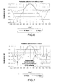
- the symmetrization of the phase response translates into a significant improvement in the radiation pattern, as shown by Figures 6 and 7 which represent, in the case of Figure 6 the radiation pattern of the horn without insert and, in the case of Figure 7, the radiation pattern of the horn with insert.
- Figures 6 and 7 represent, in the case of Figure 6 the radiation pattern of the horn without insert and, in the case of Figure 7, the radiation pattern of the horn with insert.
- the elliptical insert makes it possible to symmetrize the responses in the E and H planes while making it possible to reduce the level of the side lobes.
- the insert affords significant improvements together with a big reduction in the side lobes, this making it possible to achieve wideband operation.
- the horn may be constituted by a block of foam 10 which has been recessed internally and which exhibits an external metallization 11 and an internal metallization 12, the inside of the horn being filled with air.
- the floating insert may be fixed in a groove provided inside the horn but not represented in Figure 9.
- the horn is constituted by a solid block of foam made of a synthetic material shaped to have a cylindrical part which extends as a flared part.
- the external surface of the foam block 20 is metallized so as to make the source antenna.
- the foam horn may be made from materials known by the commercial name:
- the foam block 30 receives a metallization 31 on its external surface.
- the aperture side of the horn 30 is furnished with a nook 32 of concave shape that allows the insertion of an insert 33 made of a dielectric material, exhibiting a shape of the type of that described with reference to Figure 3.
- This insert exhibits a slightly concave profile, making it possible to reduce the phase shift of the marginal rays with respect to the central rays.
- FIG. 12 Represented in Figure 12 is a horn 40 similar to the horn of Figure 11.
- This horn is furnished on its external surface with a metallization 41 and it exhibits at the level of its aperture a nook 42 allowing the insertion of the dielectric insert 43.
- the insert 43 exhibits a profile of convex type which makes it possible, on the contrary, to increase the phase shift of the marginal rays with respect to the central rays.
- FIG. 13 Represented in Figure 13 is yet another embodiment of a horn constituted by a block of foam 50, coated on its external surface with a metallization 51.
- the foam block 50 comprises a central nook 52A for receiving a first central insert 53A made of a dielectric material and a circular groove 52B for receiving an insert formed by a circular ring 53B.
- the central insert makes it possible to correct the distortions at the level of the core of the focal spot while the insert at the periphery exhibiting the shape of a circular ring makes it possible to adapt the field distribution at the level of the periphery of the radiating aperture.
- the geometry of the radiating aperture is not limited to that of a horn, such as represented in the figures. It may have any other shape, in particular the shape of pyramidal horns or of radiating apertures exhibiting other known shapes.
- the insert of dielectric material may have shapes other than the shapes given above.
- the elliptical shape may be modified to a circular shape and the profile may have a different shape from a concave or convex shape.
Landscapes
- Engineering & Computer Science (AREA)
- Manufacturing & Machinery (AREA)
- Waveguide Aerials (AREA)
- Aerials With Secondary Devices (AREA)
Abstract
Description
- The present invention relates to source antennas constituted by a radiating aperture, more particularly by a horn. It also relates to an antenna structure comprising a source antenna in accordance with the invention, associated with a focusing system of the homogeneous lens type.
- In the case of low-orbit satellite communication systems, the use of a focusing system of the parabola type is not adequate. Specifically, in order to ensure the continuous tracking of nongeostationary satellites over their trajectory and to avoid the interruption of communication when said satellites are no longer in direct line of sight with the ground antenna, the latter must exhibit, at least during the period of switching from one satellite to another, two separate beams. Moreover, the angular coverage of the beams must be ensured over a very wide area.
- To respond to these problems, it is possible to use a focusing system of the Luneberg lens type which, by virtue of its spherical symmetry, makes it possible to envisage a multitude of beams and the tracking of satellites over a wide angular sector by simple displacement of the transmission/reception sources in the focal surface of the lens. However, the practical embodiment of a Luneberg lens is complex and expensive. Consequently, in place of a Luneberg lens, it is possible to envisage the use of a homogeneous spherical lens.
- A homogeneous lens exhibits a lower manufacturing cost. However, it does not allow perfect focusing of an incident plane wave. Specifically, aberration phenomena are noted at the level of the focal surface. In the case of a homogeneous lens, one no longer speaks of a focal point as in a focusing system constituted by a parabola or a Luneberg lens but of a focal spot, the focusing area being more extended.
- Consequently, the exit focusing imperfections of a homogeneous lens render the design constraints of the associated primary source antenna more complex. The main function of the source antenna associated with the homogeneous lenses is therefore to take into account and to compensate as well as possible for the phase and amplitude distortions introduced by this imperfect focusing system.
- Thus, the application of Robieux's theorem makes it possible to show that the efficiency of an antenna system comprising a primary source antenna and its associated focusing system is optimal when the electric field E and magnetic field H of the source antenna and of the focusing system are mutually conjugate. The distribution of the fields in the aperture of the source antenna must therefore be identical to that of the focusing system in amplitude and its phase response must be in phase opposition.
- The present invention therefore relates to a source antenna which makes it possible to obtain a distribution of the fields in its radiating aperture and which superimposes as well as possible with that generated by the focusing system. When the focusing system is a system of parabola type, the solution conventionally used for the source antenna is a horn. However, in the case of source antennas such as horns, the technique generally employed to ensure the symmetrization of the E and H planes consists in the addition of transverse or longitudinal furrows or corrugations inside or outside the horn so as to modify the modal distribution of the electromagnetic fields at the level of the aperture of the horn. The corrugations in fact introduce higher hybrid modes into the guided structure at the level of the corrugations, which make it possible to harmonize the phase- and amplitude-response in the aperture of the horn.
- However, when the focusing system is a homogeneous lens, the focusing being less effective than at the exit of a focusing system of conventional parabola type, this translates into a much more extended focusing area. Therefore, corrugated horns do not constitute the best solution in the case of a focusing system of the homogeneous lens type.
- Consequently, the present invention proposes another solution for the source antenna constituted by a radiating aperture.
- In accordance with the invention, the antenna consists of a source antenna of radiating aperture type inside which is disposed a dielectric insert. The use of the dielectric insert makes it possible:
- 1) to establish the symmetry of the phase response, in particular on account of the fact that, according to a characteristic of the invention, the insert exhibits, along a section transverse to the aperture, an elliptical shape,
- 2) to adapt the phase- and amplitude-response of the source antenna to that of the homogeneous lens by altering the positioning and the longitudinal profile of the dielectric insert. In particular the insert exhibits along a section made along the axis Oz of radiation of the aperture a concave or convex shape. This specific shape will modify the optical path, hence the phase response inside the radiating aperture and the amplitude distribution.
-
- According to another characteristic of the present invention, the radiating aperture is constituted by a horn.
- According to a first embodiment, the horn is formed by a block of foam made of synthetic material whose external surface is metallized, the said block exhibiting an internal recess for receiving the insert.
- According to another embodiment, the horn is constituted by a block of foam made of synthetic material recessed internally and exhibiting metallized internal and external surfaces.
- The present invention also relates to an antenna structure comprising a source antenna such as described above, associated with a focusing system of the homogeneous lens type.
- Other characteristics and advantages of the present invention will become apparent on reading the description given hereinafter of various embodiments, this description being given with reference to the annexed figures in which:
- Fig. 1 depicts respectively a view in transverse and longitudinal section of a source of horn type furnished with a dielectric insert.
- Fig. 2 depicts the phase charts in the case of a horn without insert and of a horn with insert.
- Fig. 3 are diagrammatic front and profile views of the geometry of the insert.
- Fig. 4 is a curve giving the amplitude of the E field along the axis
O
x for the lens, the horn alone and the horn with insert. - Figs 5A and 5B are curves identical to that of Fig. 4 in the case of
the phase of the E field and of the H field along the axis O
x. - Fig. 6 represents the radiation pattern in the E and H planes of a source antenna of horn without insert type.
- Fig. 7 represents the radiation pattern in the E and H planes of a source antenna of horn with insert type.
- Fig. 8 represents various radiation patterns at 16 GHz.
- Fig. 9 is a diagrammatic view of a first embodiment of a horn.
- Fig. 10 is a diagrammatic view of a second embodiment of a horn.
- Fig. 11 is a sectional view of an embodiment of a horn furnished with an insert, in accordance with the present invention.
- Fig. 12 is a sectional view identical to Fig. 11 for a second embodiment, and
- Fig. 13 is a sectional view identical to those of Figs 11 and 12 for a third embodiment.
-
- To simplify the description in the figures, the same elements bear the same references.
- An embodiment of the source antenna in accordance with the present invention will firstly be described with reference to Figs 1 to 8. In this case, as represented in Fig. 1, the radiating aperture forming the source antenna is constituted by a
horn 1 made of a radiating material exhibiting, at one end, acylindrical shape 1a which flares out progressively up to itsaperture 1b. - In accordance with the invention, inside the
horn 1 is mounted aninsert 2 made of a dielectric material. - The materials that may be used are the materials known by the commercial name:
- Eccostock Lok: permittivity 1.7 loss tangent 0.004
- Eccostock SH-14: permittivity 1.25 loss tangent 0.005
-
- In a general manner, any dielectric material of permittivity > 1 and with a low enough loss tangent to minimize the dielectric losses may be used, this material possibly being machinable or mouldable.
- As represented clearly in the cross section of Figure 1, the
dielectric insert 2 exhibits an elliptical front view. In fact, the shape of the insert is represented in greater detail in Figure 3. The left-hand view of Figure 3 represents the elliptical face of theinsert 2 while the right-hand view is a profile view and shows that theinsert 2 has a concave shape, according to its longitudinal profile. The insert dimensions given in Figure 3 will be used subsequently for simulations. - The role of the dielectric insert is represented in Figure 2 which gives the phase charts obtained in the aperture of a conventional horn linearly polarized along the axis Ox, respectively in the case where the horn has no insert (left-hand figure), and in the case where the horn has an elliptical dielectric insert (right-hand figure). As is clearly apparent in the figures, the addition of the elliptical insert makes it possible to symmetrize the phase response in the aperture of the horn. This translates, at the level of the radiation pattern, into a symmetrization in the E and H planes.
- Moreover, the geometry of the dielectric insert is important for obtaining this symmetrization. The elliptical nature of the insert is necessary to ensure the symmetrization of the phase response, the elliptical profile being all the more accentuated the bigger the phase dissymmetry of the horn without insert.
- Moreover, the longitudinal profile of the slightly concave insert, as illustrated in Figure 3, and the positioning of the insert inside the horn are two parameters that make it possible to adapt, in an optimal manner, the phase- and amplitude-response with respect to the desired response of a given lens. The positioning of the insert along the axis Oz greatly influences the amplitude correction, the concave profile allowing it to reduce the phase shift between central and marginal rays.
- The results obtained by the insertion of an elliptical insert into a horn such as represented in Figure 1 have been verified using the programme known by the trade name "Feko" on the basis of a horn excited by a linear polarization along the axis Ox at 12 GHz. The horn has been dimensioned in such a way as to ensure the illumination of a homogeneous dielectric lens of permittivity 1.5 and 30 cm in diameter. This horn exhibits a diameter of 4 cm at the level of the top-centred radiating aperture and the insert exhibits the dimensions given in Figure 3, namely a major axis of the ellipse of 14 mm, a minor axis of 7 mm and a depth between the two concave parts of 18 mm with a permittivity of 1.4. The results of the simulations are given in the
various curves - Moreover, the symmetrization of the phase response translates into a significant improvement in the radiation pattern, as shown by Figures 6 and 7 which represent, in the case of Figure 6 the radiation pattern of the horn without insert and, in the case of Figure 7, the radiation pattern of the horn with insert. In these figures, it is seen that the elliptical insert makes it possible to symmetrize the responses in the E and H planes while making it possible to reduce the level of the side lobes.
- Thus, as represented in Figure 8, the insert affords significant improvements together with a big reduction in the side lobes, this making it possible to achieve wideband operation.
- Various embodiments of a source antenna of horn type as well as various embodiments of the present invention will now be described with reference to Figures 9 to 13.
- As represented in Figure 9, the horn may be constituted by a block of
foam 10 which has been recessed internally and which exhibits anexternal metallization 11 and aninternal metallization 12, the inside of the horn being filled with air. In this case, the floating insert may be fixed in a groove provided inside the horn but not represented in Figure 9. - Represented in Figure 10 is another embodiment of a horn using the foam technology. In this case, the horn is constituted by a solid block of foam made of a synthetic material shaped to have a cylindrical part which extends as a flared part. In this case, the external surface of the
foam block 20 is metallized so as to make the source antenna. - The foam horn may be made from materials known by the commercial name:
- Rohacell 71: permittivity 1.09 loss tangent 0.0038 or,
- Eccostock PP: permittivity range from 1.03 to 1.1 loss tangent 0.0002.
-
- Various alternative embodiments of the horn in the case where the horn is constituted by a metallized foam block, as described with reference to Figure 10, will now be described with reference to Figures 11, 12 and 13.
- In the case of Figure 11, the
foam block 30 receives ametallization 31 on its external surface. Moreover, the aperture side of thehorn 30 is furnished with anook 32 of concave shape that allows the insertion of aninsert 33 made of a dielectric material, exhibiting a shape of the type of that described with reference to Figure 3. This insert exhibits a slightly concave profile, making it possible to reduce the phase shift of the marginal rays with respect to the central rays. - Represented in Figure 12 is a
horn 40 similar to the horn of Figure 11. This horn is furnished on its external surface with ametallization 41 and it exhibits at the level of its aperture anook 42 allowing the insertion of thedielectric insert 43. However, in this embodiment, theinsert 43 exhibits a profile of convex type which makes it possible, on the contrary, to increase the phase shift of the marginal rays with respect to the central rays. - Represented in Figure 13 is yet another embodiment of a horn constituted by a block of
foam 50, coated on its external surface with ametallization 51. In this case, severaldielectric inserts foam block 50 comprises acentral nook 52A for receiving a firstcentral insert 53A made of a dielectric material and acircular groove 52B for receiving an insert formed by acircular ring 53B. In this case, the central insert makes it possible to correct the distortions at the level of the core of the focal spot while the insert at the periphery exhibiting the shape of a circular ring makes it possible to adapt the field distribution at the level of the periphery of the radiating aperture. - It is obvious to the person skilled in the art that the embodiments given above are merely examples that may be modified in numerous ways. In particular the geometry of the radiating aperture is not limited to that of a horn, such as represented in the figures. It may have any other shape, in particular the shape of pyramidal horns or of radiating apertures exhibiting other known shapes. Likewise the insert of dielectric material may have shapes other than the shapes given above. In particular the elliptical shape may be modified to a circular shape and the profile may have a different shape from a concave or convex shape.
Claims (8)
- Source antenna constituted by a radiating aperture, characterized in that it comprises at least one insert (2) made of a dielectric material mounted floating inside the radiating aperture (1).
- Source antenna according to Claim 1, characterized in that the insert exhibits, along a section transverse to the aperture, an elliptical shape.
- Source antenna according to Claim 1 or 2, characterized in that the insert exhibits, along a section made along the axis (Oz) of radiation of the aperture, a concave or convex shape.
- Source antenna according to one of Claims 1 to 3, characterized in that the insert is positioned inside the aperture along the axis (Oz) of radiation of the aperture, as a function of the amplitude correction requested.
- Source antenna according to one of Claims 1 to 4, characterized in that the radiating aperture is constituted by a horn.
- Source antenna according to Claim 5, characterized in that the horn is constituted by a block of foam made of synthetic material whose external surface is metallized, the said block exhibiting an internal recess for receiving the insert.
- Source antenna according to Claim 5, characterized in that the horn is constituted by a block of foam made of synthetic material recessed internally and exhibiting metallized internal and external surfaces.
- Antenna structure comprising a source antenna according to one of Claims 1 to 7, associated with a focusing system of the homogeneous lens type.
Applications Claiming Priority (2)
| Application Number | Priority Date | Filing Date | Title |
|---|---|---|---|
| FR0350767 | 2003-10-31 | ||
| FR0350767A FR2861899A1 (en) | 2003-10-31 | 2003-10-31 | ANTENNA-SOURCE CONSISTING OF A RADIANT OPENING COMPOTING AN INSERT |
Publications (1)
| Publication Number | Publication Date |
|---|---|
| EP1530259A1 true EP1530259A1 (en) | 2005-05-11 |
Family
ID=34430066
Family Applications (1)
| Application Number | Title | Priority Date | Filing Date |
|---|---|---|---|
| EP04104946A Withdrawn EP1530259A1 (en) | 2003-10-31 | 2004-10-08 | Improvement to source antennas with radiating aperture |
Country Status (6)
| Country | Link |
|---|---|
| US (1) | US7528787B2 (en) |
| EP (1) | EP1530259A1 (en) |
| JP (1) | JP2005137010A (en) |
| KR (1) | KR20050041921A (en) |
| CN (1) | CN1612413A (en) |
| FR (1) | FR2861899A1 (en) |
Families Citing this family (3)
| Publication number | Priority date | Publication date | Assignee | Title |
|---|---|---|---|---|
| DE102007009363B4 (en) * | 2007-02-23 | 2013-09-19 | KROHNE Meßtechnik GmbH & Co. KG | Antenna for a radar-based level measuring device |
| RU169524U1 (en) * | 2016-07-18 | 2017-03-22 | федеральное государственное бюджетное образовательное учреждение высшего образования "Воронежский государственный университет" (ФГБОУ ВО "ВГУ") | WIDTH TEM HORN ANTENNA WITH HETEROGENEOUS DIELECTRIC FILLING OF THE OPENING SPACE |
| US10484120B2 (en) * | 2017-09-30 | 2019-11-19 | Intel Corporation | Waveguide couplers and junctions to enable frequency division multiplexed sensor systems in autonomous vehicle |
Citations (3)
| Publication number | Priority date | Publication date | Assignee | Title |
|---|---|---|---|---|
| JPH04301902A (en) * | 1991-03-28 | 1992-10-26 | Mitsubishi Electric Corp | horn antenna |
| US20030167839A1 (en) * | 2000-08-21 | 2003-09-11 | Stefan Burger | Device for dertermining the level of a filter material in a container |
| FR2838245A1 (en) * | 2002-04-04 | 2003-10-10 | Thomson Licensing Sa | Structure of antenna used for LDMS telecommunications and multimedia networks, has a compact design and is lightweight |
Family Cites Families (11)
| Publication number | Priority date | Publication date | Assignee | Title |
|---|---|---|---|---|
| US4788553A (en) * | 1983-04-06 | 1988-11-29 | Trw Inc. | Doppler radar velocity measurement apparatus |
| JPS61163704A (en) * | 1985-01-16 | 1986-07-24 | Junkosha Co Ltd | Dielectric line |
| NO157480C (en) * | 1985-02-28 | 1988-03-30 | Sintef | HYBRID MODE HORNANTENNE. |
| US5166698A (en) * | 1988-01-11 | 1992-11-24 | Innova, Inc. | Electromagnetic antenna collimator |
| US5706017A (en) * | 1993-04-21 | 1998-01-06 | California Institute Of Technology | Hybrid antenna including a dielectric lens and planar feed |
| US5883604A (en) * | 1994-10-20 | 1999-03-16 | Lockheed Fort Worth Company | Horn antenna |
| US5872494A (en) * | 1997-06-27 | 1999-02-16 | Rosemount Inc. | Level gage waveguide process seal having wavelength-based dimensions |
| US6661389B2 (en) * | 2000-11-20 | 2003-12-09 | Vega Grieshaber Kg | Horn antenna for a radar device |
| US20020101387A1 (en) * | 2001-01-30 | 2002-08-01 | Brandau Ronald J. | Dielectric loaded feed horn |
| US6891513B2 (en) * | 2001-11-26 | 2005-05-10 | Vega Greishaber, Kg | Antenna system for a level measurement apparatus |
| SE0200792D0 (en) * | 2002-03-18 | 2002-03-18 | Saab Marine Electronics | Horn Antenna |
-
2003
- 2003-10-31 FR FR0350767A patent/FR2861899A1/en active Pending
-
2004
- 2004-10-08 EP EP04104946A patent/EP1530259A1/en not_active Withdrawn
- 2004-10-28 KR KR1020040086614A patent/KR20050041921A/en not_active Withdrawn
- 2004-10-28 US US10/975,800 patent/US7528787B2/en not_active Expired - Fee Related
- 2004-10-29 CN CNA2004100959950A patent/CN1612413A/en active Pending
- 2004-10-29 JP JP2004316412A patent/JP2005137010A/en active Pending
Patent Citations (3)
| Publication number | Priority date | Publication date | Assignee | Title |
|---|---|---|---|---|
| JPH04301902A (en) * | 1991-03-28 | 1992-10-26 | Mitsubishi Electric Corp | horn antenna |
| US20030167839A1 (en) * | 2000-08-21 | 2003-09-11 | Stefan Burger | Device for dertermining the level of a filter material in a container |
| FR2838245A1 (en) * | 2002-04-04 | 2003-10-10 | Thomson Licensing Sa | Structure of antenna used for LDMS telecommunications and multimedia networks, has a compact design and is lightweight |
Non-Patent Citations (3)
| Title |
|---|
| AVERTY F ET AL: "Optimization of the electromagnetic fields at the aperture of a wave guide horn by using a floating dielectric insert, in foam technology", ANTENNAS AND PROPAGATION SOCIETY SYMPOSIUM, 2004. IEEE MONTEREY, CA, USA JUNE 20-25, 2004, PISCATAWAY, NJ, USA,IEEE, vol. 2, 20 June 2004 (2004-06-20), pages 1547 - 1550, XP010721640, ISBN: 0-7803-8302-8 * |
| PATENT ABSTRACTS OF JAPAN vol. 0171, no. 25 (E - 1332) 16 March 1993 (1993-03-16) * |
| PHILIPS B ET AL: "Design and performance of profiled dielectric loaded horns", IEE PROCEEDINGS: MICROWAVES, ANTENNAS AND PROPAGATION, IEE, STEVENAGE, HERTS, GB, vol. 141, no. 5, 1 October 1994 (1994-10-01), pages 337 - 41, XP006001954, ISSN: 1350-2417 * |
Also Published As
| Publication number | Publication date |
|---|---|
| US7528787B2 (en) | 2009-05-05 |
| FR2861899A1 (en) | 2005-05-06 |
| KR20050041921A (en) | 2005-05-04 |
| CN1612413A (en) | 2005-05-04 |
| JP2005137010A (en) | 2005-05-26 |
| US20050093759A1 (en) | 2005-05-05 |
Similar Documents
| Publication | Publication Date | Title |
|---|---|---|
| US10224638B2 (en) | Lens antenna | |
| US7205950B2 (en) | Radio wave lens antenna | |
| US7656358B2 (en) | Antenna operable at two frequency bands simultaneously | |
| US7656359B2 (en) | Apparatus and method for antenna RF feed | |
| US5117240A (en) | Multimode dielectric-loaded double-flare antenna | |
| US7847749B2 (en) | Integrated waveguide cavity antenna and reflector RF feed | |
| KR101292230B1 (en) | Compact nonaxisymmetric double-reflector antenna | |
| CA2058628A1 (en) | Electromagnetic antenna collimator | |
| US4855751A (en) | High-efficiency multibeam antenna | |
| US20220247067A1 (en) | Base station antenna | |
| CN112909559B (en) | Offset-feed type reflecting surface sum-difference network antenna | |
| US10553957B2 (en) | Antenna integrating delay lenses in the interior of a distributor based on parallel-plate waveguide dividers | |
| US20150288068A1 (en) | Primary radiator | |
| US7528787B2 (en) | Source antennas with radiating aperture | |
| EP1184939B1 (en) | Gridded reflector antenna | |
| EP1207584B1 (en) | Integrated dual beam reflector antenna | |
| EP0164466B1 (en) | High-efficiency multibeam antenna | |
| CN108649345A (en) | A kind of confocal dual paraboloid antenna | |
| US6633264B2 (en) | Earth coverage reflector antenna for geosynchronous spacecraft | |
| US20020005813A1 (en) | Shaped reflector antenna assembly | |
| CN121618201A (en) | Bullseye antenna unit, array and superlens structure | |
| JPS6036643B2 (en) | Multi-horn fed offset parabolic antenna | |
| JPS59231903A (en) | Electromagnetic lens antenna | |
| BR202018010827Y1 (en) | CONSTRUCTIVE ARRANGEMENT INTRODUCED IN LNBF WITH DIELECTRIC LENS FOR APPLICATION IN SATELLITE ANTENNAS | |
| MXPA01000683A (en) | Shaped reflector antenna assembly |
Legal Events
| Date | Code | Title | Description |
|---|---|---|---|
| PUAI | Public reference made under article 153(3) epc to a published international application that has entered the european phase |
Free format text: ORIGINAL CODE: 0009012 |
|
| AK | Designated contracting states |
Kind code of ref document: A1 Designated state(s): AT BE BG CH CY CZ DE DK EE ES FI FR GB GR HU IE IT LI LU MC NL PL PT RO SE SI SK TR |
|
| AX | Request for extension of the european patent |
Extension state: AL HR LT LV MK |
|
| RAP1 | Party data changed (applicant data changed or rights of an application transferred) |
Owner name: THOMSON LICENSING |
|
| 17P | Request for examination filed |
Effective date: 20051021 |
|
| AKX | Designation fees paid |
Designated state(s): DE FR GB IT |
|
| RAP1 | Party data changed (applicant data changed or rights of an application transferred) |
Owner name: THOMSON LICENSING |
|
| 17Q | First examination report despatched |
Effective date: 20110114 |
|
| STAA | Information on the status of an ep patent application or granted ep patent |
Free format text: STATUS: THE APPLICATION IS DEEMED TO BE WITHDRAWN |
|
| 18D | Application deemed to be withdrawn |
Effective date: 20110503 |