EP1530243A2 - An electricity generator device including a combustor matrix of porous semi-conductor material - Google Patents
An electricity generator device including a combustor matrix of porous semi-conductor material Download PDFInfo
- Publication number
- EP1530243A2 EP1530243A2 EP04026127A EP04026127A EP1530243A2 EP 1530243 A2 EP1530243 A2 EP 1530243A2 EP 04026127 A EP04026127 A EP 04026127A EP 04026127 A EP04026127 A EP 04026127A EP 1530243 A2 EP1530243 A2 EP 1530243A2
- Authority
- EP
- European Patent Office
- Prior art keywords
- pores
- separation element
- chamber
- region
- semi
- Prior art date
- Legal status (The legal status is an assumption and is not a legal conclusion. Google has not performed a legal analysis and makes no representation as to the accuracy of the status listed.)
- Withdrawn
Links
Images

Classifications
-
- F—MECHANICAL ENGINEERING; LIGHTING; HEATING; WEAPONS; BLASTING
- F23—COMBUSTION APPARATUS; COMBUSTION PROCESSES
- F23C—METHODS OR APPARATUS FOR COMBUSTION USING FLUID FUEL OR SOLID FUEL SUSPENDED IN A CARRIER GAS OR AIR
- F23C99/00—Subject-matter not provided for in other groups of this subclass
- F23C99/006—Flameless combustion stabilised within a bed of porous heat-resistant material
-
- H—ELECTRICITY
- H10—SEMICONDUCTOR DEVICES; ELECTRIC SOLID-STATE DEVICES NOT OTHERWISE PROVIDED FOR
- H10N—ELECTRIC SOLID-STATE DEVICES NOT OTHERWISE PROVIDED FOR
- H10N10/00—Thermoelectric devices comprising a junction of dissimilar materials, i.e. devices exhibiting Seebeck or Peltier effects
- H10N10/10—Thermoelectric devices comprising a junction of dissimilar materials, i.e. devices exhibiting Seebeck or Peltier effects operating with only the Peltier or Seebeck effects
- H10N10/13—Thermoelectric devices comprising a junction of dissimilar materials, i.e. devices exhibiting Seebeck or Peltier effects operating with only the Peltier or Seebeck effects characterised by the heat-exchanging means at the junction
Definitions
- the present invention relates to an electricity generator including a combustor in the form of a matrix of porous semiconductor material.
- the device according to the invention is an electricity generator which is characterised in that it comprises a combustor including an inlet region or chamber intended to receive a flow of fuel and a combustion supporter or comburent at high pressure, an outlet region or chamber or exhaust for the combustion products at a relatively lower pressure, and at least one separation element of nano-porous or micro-porous semi-conductor material which separates the inlet region or chamber from the outlet region or chamber; this separation element having a plurality of nano-pores or micro-pores passing therethrough which define communication passages between the inlet region or chamber and the outlet region or chamber; the surface of the said or nano-pores or micro-pores are at least partly clad with a layer of electrically conductive or semi-conductive material which, relative to the material of the said separation element, form a substantially extensive p-n junction; and first and second electrodes connected to the said nano-porous or micro-porous cladding and respectively to the semi-conductor material of the separation element; and the arrangement being
- FIG. 1 an electricity generator according to the invention is generally indicated 1.
- This electricity generator 1 includes a combustor generally indicated 2.
- this combustor comprises a casing 3 at a first end of which is defined an inlet region or chamber 4 intended to receive in operation a flow of fuel 5 and flow of combustion supporter 6 at high pressure.
- an outlet region or chamber 7 for exhaust of the combustion products At the opposite end of the casing 3 is defined an outlet region or chamber 7 for exhaust of the combustion products.
- the exhaust gases or combustion products are symbolically represented by the arrow 8.
- a separation element 9 essentially in the form of a sheet or disc of nano-porous or micro-porous semi-conductor material.
- the separation element 9 is conveniently made of silicon and has a plurality of nano-pores or micro-pores 10 passing therethrough which define communication passages between the inlet region or chamber 4 and the outlet region or chamber 7.
- the surface of the pores 10 passing through the separation element 9 is at least partly provided with a cladding formed by a layer of electrically conductive or semi-conductive material 11.
- the said cladding material forms a substantially extended p-n junction with respect to the semi-conductor material of the separation element 9.
- the material of the cladding 11 of the nano-pores or micro-pores 10 is for example constituted by a noble metal, preferably palladium or gold, or by a doped semi-conductor material so as to present a conductivity of predetermined type or sign.
- Formation of the through pores 10 can moreover be achieved by means of anodisation in a bath of hydrofluoric acid.
- the typical currents to obtain nano-porous silicon are of the order of 10 mA/cm 2 .
- the duration of this process must be sufficient to achieve pores passing through the separation element 9.
- the cladding of the wall of the nano-pores or micro-pores 10 can be formed with sol gel deposition techniques or, more generally, with CSD (Chemical Solution Deposition) techniques, or else by sputtering, or more generally with CVD (Chemical Vapour Deposition) techniques.
- CSD Chemical Solution Deposition
- CVD Chemical Vapour Deposition
- the claddings 11 of the individual pores 10 passing therethrough are interconnected by a cladding 12 which extends over a principal surface or face of the separation element 9.
- this principal surface or face is the upper-face, facing the inlet region or chamber 4 of the combustor.
- Two electrodes are connected to the cladding 12 and, respectively, to the semi-conductor material which constitutes the separation element 9 in the form of sheet or disc.
- the arrangement is such that in operation the pores 10 of the separation element 9 act as resonant micro-chambers in which a rapid confined combustion of the fuel 5 with the fuel supporter 6 takes place. Part of the energy developed by the combustion in each pore 10 passing therethrough is directly converted into an electron-hole pair.
- the reaction enthalpy of a combustion is of the order of 10 eV/molecule, whilst the energy necessary for the formation of an excitation (electron-hole pair) is typically 1 eV.
- the energy developed by the combustion process principally manifests itself in the form of kinetic energy of the molecules of the reaction products (it can also partly develop as visible or infrared photons for example flame). Given that the combustion takes place in a confined space of the dimensions of several tens of nm or less, the kinetic modes of the gas molecules are strongly inhibited. The energy associated with these modes must nevertheless be dissipated in some way and this takes place in part in the form of phonons (on the surface of the pores 10 which host the reaction) and partly in the form of electronic excitation of the atoms of the walls of the said pores (by kinetic energy of the gas upon excitation of the electrons). The phonons cause an increase in the temperature of the walls of the cavity.
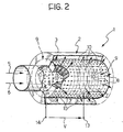
- the separation element 9 of semiconductor material has an essentially tubular form and the said nano-pores or micro-pores 10 extend essentially radially between the inner surface and the outer surface thereof.
- inlet region or chamber 4 for the fuel 5 and the combustion supporter 6 correspond to the internal region of the tubular separation element 9, whilst the outlet region or chamber 7 for the exhaust of the combustion products 8 surrounds the separation element 9.
- the surface of the pores 10 passing therethrough is also provided with a layer of electrically conductive or semi-conductive cladding material capable of forming, together with the semi-conductor material which constitutes the separation element 9, an extended p-n junction.
- the claddings of the pores 10 of the separation element 9 are interconnected by a cladding 12 which extends for example onto the outer surface of the separation element 9.
Landscapes
- Engineering & Computer Science (AREA)
- Chemical & Material Sciences (AREA)
- Combustion & Propulsion (AREA)
- Mechanical Engineering (AREA)
- General Engineering & Computer Science (AREA)
- Physical Or Chemical Processes And Apparatus (AREA)
- Incineration Of Waste (AREA)
- Wick-Type Burners And Burners With Porous Materials (AREA)
Abstract
Description
a combustor including
an inlet region or chamber intended to receive a flow of fuel and a combustion supporter or comburent at high pressure,
an outlet region or chamber or exhaust for the combustion products at a relatively lower pressure, and
at least one separation element of nano-porous or micro-porous semi-conductor material which separates the inlet region or chamber from the outlet region or chamber; this separation element having a plurality of nano-pores or micro-pores passing therethrough which define communication passages between the inlet region or chamber and the outlet region or chamber; the surface of the said or nano-pores or micro-pores are at least partly clad with a layer of electrically conductive or semi-conductive material which, relative to the material of the said separation element, form a substantially extensive p-n junction; and
first and second electrodes connected to the said nano-porous or micro-porous cladding and respectively to the semi-conductor material of the separation element; and
the arrangement being such that in operation the said nano-pores or micro-pores passing therethrough of the separation element function as confined combustion micro-chambers and the energy developed by the combustion is capable of causing at the said p-n junction the creation of stable electron-hole pairs and the generation of a corresponding potential difference between the said electrodes.
Claims (5)
- An electricity generator device (1) including
a combustor (2) comprising
an inlet region or chamber (4) intended to receive a flow of fuel (5) and a combustion supporter (6) at high pressure,
an outlet region or chamber (7) or combustion product exhaust (8) at relatively lower pressure, and
at least one separation element (9) of nano-porous or micro-porous semi-conductor material which separates the inlet region or chamber (4) from the outlet region or chamber (7); the separation element (9) having a plurality of nano-pores or micro-pores (10) passing therethrough which define communication passages between the inlet region or chamber (4) and the outlet region or chamber (7); the surface of the said pores (10) passing therethrough being at least partly clad in a layer (11) of electrically conductive or semi-conductive material which, relative to the semi-conductor material of the separation element (9), substantially forms an extended junction, in particular a p-n junction or a Schottky junction or a hetero junction; and
first and second electrodes (13, 14) connected to the cladding (11) of the said pores (10) passing therethrough and, respectively, to the semi-conductor material of the separation element (9);
the arrangement being such that in operation the said pores (10) passing therethrough act as confined combustion microchambers and the energy developed by the combustion is capable of causing, in the said junction, the creation of stable electron-hole pairs and the generation of a corresponding potential difference (V) between the said electrodes (13, 14). - An electricity generator device according to Claim 1, in which the semi-conductor material of the separation element (9) is silicon, and the cladding (11) of its pores (10) passing therethrough is made of a catalyzing material or a noble metal, in particular palladium or gold or platinum, or with a doped semi-conductor material having a conductivity of predetermined type or sign.
- An electricity generator device according to Claim 1 or Claim 2, in which the separation element (9) is made in the form of disc or sheet.
- An electricity generator device according to Claim 1 or Claim 2, in which the separation element (9) is essentially of tubular form and the said pores (10, 11) passing therethrough extend between its internal surface and its external surface.
- An electricity generator device according to any preceding claim, in which the claddings (11) of the pores (10) passing through the separation element (9) are interconnected by a cladding (12) which extends over a principal face or surface of the separation element (9) facing the inlet chamber or region (4) or the outlet chamber or region (7).
Applications Claiming Priority (2)
| Application Number | Priority Date | Filing Date | Title |
|---|---|---|---|
| IT000882A ITTO20030882A1 (en) | 2003-11-07 | 2003-11-07 | ELECTRIC GENERATOR DEVICE INCLUDING A COMBUSTOR WITH A POROUS MATERIAL MATERIAL. |
| ITTO20030882 | 2003-11-07 |
Publications (2)
| Publication Number | Publication Date |
|---|---|
| EP1530243A2 true EP1530243A2 (en) | 2005-05-11 |
| EP1530243A3 EP1530243A3 (en) | 2007-03-14 |
Family
ID=34430813
Family Applications (1)
| Application Number | Title | Priority Date | Filing Date |
|---|---|---|---|
| EP04026127A Withdrawn EP1530243A3 (en) | 2003-11-07 | 2004-11-04 | An electricity generator device including a combustor matrix of porous semi-conductor material |
Country Status (5)
| Country | Link |
|---|---|
| US (1) | US20050155639A1 (en) |
| EP (1) | EP1530243A3 (en) |
| JP (1) | JP2005143286A (en) |
| CN (1) | CN1614868A (en) |
| IT (1) | ITTO20030882A1 (en) |
Cited By (3)
| Publication number | Priority date | Publication date | Assignee | Title |
|---|---|---|---|---|
| RU2426906C2 (en) * | 2009-07-02 | 2011-08-20 | Государственное образовательное учреждение высшего профессионального образования "Санкт-Петербургский государственный технологический институт (технический университет)" | Intensification method of operation of burners and internal combustion engines |
| WO2012004472A1 (en) * | 2010-07-06 | 2012-01-12 | Commissariat à l'Energie Atomique et aux Energies Alternatives | Device for generating current and/or voltage based on a thermoelectric module placed in a flowing fluid |
| WO2013037689A1 (en) * | 2011-09-14 | 2013-03-21 | Emitec Gesellschaft Für Emissionstechnologie Mbh | Thermoelectric generator having a compact design |
Families Citing this family (5)
| Publication number | Priority date | Publication date | Assignee | Title |
|---|---|---|---|---|
| WO2006138211A2 (en) * | 2005-06-17 | 2006-12-28 | University Of Delaware | Catalytic microcombustors for compact power or heat generation |
| MX2012002417A (en) * | 2009-08-27 | 2012-06-19 | Landa Labs 2012 Ltd | Method and device for generating electricity and method of fabrication thereof. |
| US9196916B2 (en) | 2012-12-04 | 2015-11-24 | Syracuse University | Non-propulsive miniature power device based on solid oxide fuel cell and combustion-driven thermal transpiration pump |
| FR3031795B1 (en) * | 2015-01-20 | 2019-11-01 | Commissariat A L'energie Atomique Et Aux Energies Alternatives | COMBUSTION MODULE WITH SUBSTANTIALLY UNIFORM TEMPERATURE |
| FR3031797B1 (en) * | 2015-01-20 | 2017-03-03 | Commissariat Energie Atomique | COMBUSTION MODULE HAVING IMPROVED OPERATING SAFETY AND OPTIMIZED THERMAL EFFICIENCY |
Family Cites Families (8)
| Publication number | Priority date | Publication date | Assignee | Title |
|---|---|---|---|---|
| GB1113396A (en) * | 1966-02-04 | 1968-05-15 | Int Nickel Ltd | Improvements relating to thermo-electric generators |
| US3881962A (en) * | 1971-07-29 | 1975-05-06 | Gen Atomic Co | Thermoelectric generator including catalytic burner and cylindrical jacket containing heat exchange fluid |
| US5834828A (en) * | 1993-09-20 | 1998-11-10 | The United States Of America, As Represented By The Secretary Of The Army | Nanoporous semiconductor material and fabrication technique for use as thermoelectric elements |
| JP2001210879A (en) * | 1999-11-17 | 2001-08-03 | Sumitomo Metal Ind Ltd | High output porous thermoelectric conversion element |
| JP2003533956A (en) * | 2000-01-07 | 2003-11-11 | ユニバーシティ・オブ・サザン・カリフォルニア | Micro-combustors and thermoelectric micro-generators based on combustion |
| JP4538981B2 (en) * | 2001-04-23 | 2010-09-08 | トヨタ自動車株式会社 | Thermolight generator |
| JP2003070274A (en) * | 2001-08-22 | 2003-03-07 | Hakukin Warmers Co Ltd | Portable thermoelectric generator |
| US6699032B2 (en) * | 2002-02-26 | 2004-03-02 | General Motors Corporation | Catalytic combustion of storage tank off-gases |
-
2003
- 2003-11-07 IT IT000882A patent/ITTO20030882A1/en unknown
-
2004
- 2004-11-02 JP JP2004319349A patent/JP2005143286A/en not_active Withdrawn
- 2004-11-04 EP EP04026127A patent/EP1530243A3/en not_active Withdrawn
- 2004-11-04 US US10/980,153 patent/US20050155639A1/en not_active Abandoned
- 2004-11-05 CN CNA2004100922316A patent/CN1614868A/en active Pending
Cited By (5)
| Publication number | Priority date | Publication date | Assignee | Title |
|---|---|---|---|---|
| RU2426906C2 (en) * | 2009-07-02 | 2011-08-20 | Государственное образовательное учреждение высшего профессионального образования "Санкт-Петербургский государственный технологический институт (технический университет)" | Intensification method of operation of burners and internal combustion engines |
| WO2012004472A1 (en) * | 2010-07-06 | 2012-01-12 | Commissariat à l'Energie Atomique et aux Energies Alternatives | Device for generating current and/or voltage based on a thermoelectric module placed in a flowing fluid |
| FR2962597A1 (en) * | 2010-07-06 | 2012-01-13 | Commissariat Energie Atomique | DEVICE FOR GENERATING CURRENT AND / OR VOLTAGE BASED ON THERMOELECTRIC MODULE ARRANGED IN A FLOW OF FLUID. |
| US9099942B2 (en) | 2010-07-06 | 2015-08-04 | Commissariat A L'energie Atomique Et Aux Energies Alternatives | Device for generating current and/or voltage based on a thermoelectric module placed in a flowing fluid |
| WO2013037689A1 (en) * | 2011-09-14 | 2013-03-21 | Emitec Gesellschaft Für Emissionstechnologie Mbh | Thermoelectric generator having a compact design |
Also Published As
| Publication number | Publication date |
|---|---|
| EP1530243A3 (en) | 2007-03-14 |
| CN1614868A (en) | 2005-05-11 |
| US20050155639A1 (en) | 2005-07-21 |
| JP2005143286A (en) | 2005-06-02 |
| ITTO20030882A1 (en) | 2005-05-08 |
Similar Documents
| Publication | Publication Date | Title |
|---|---|---|
| JP6937404B2 (en) | Pre-equilibrium systems and methods using nanodesign porous network structural materials and solid-state devices as energy transducers | |
| JP5676377B2 (en) | Electret film and vibration power generation element using the same | |
| US20050155639A1 (en) | Electricity generator device including a combustor martix of porous semi-conductor material | |
| US8354729B2 (en) | Gas sensor and manufacturing method thereof | |
| JP6730069B2 (en) | Nitrogen oxide gas sensor and oxygen pump | |
| JP2002100789A (en) | Solar cell manufacturing method | |
| US9607815B2 (en) | Low work-function, mechanically and thermally robust emitter for thermionic energy converters | |
| TW201023408A (en) | Thermoelectric device | |
| US6220164B1 (en) | Semiconductor igniter | |
| JP2012507855A (en) | Method for forming a multi-doped junction on a substrate | |
| TW201121066A (en) | Bificial solar cell | |
| CN104272086A (en) | Infrared radiation element | |
| TW201521208A (en) | Epitaxial solar cell with moisture barrier | |
| JPH06310740A (en) | Solar cell and manufacturing method thereof | |
| US20070034426A1 (en) | Motor vehicle with thermal electric power generation apparatus | |
| CN103472097B (en) | Micro gas sensor recoverable for repeated preparation and preparation method thereof | |
| CN102947954B (en) | Solaode and manufacture method thereof with dielectric back reflection coating | |
| TW201020343A (en) | A hydrogen-oxygen mixed gas generator | |
| JP5018688B2 (en) | Film forming apparatus and film forming method | |
| CN110024145B (en) | Thermoelectric module and thermoelectric generator | |
| KR101407165B1 (en) | Method of forming LBSF back electrode of solar cell | |
| Tu et al. | Micromachined, silicon filament light source for spectrophotometric microsystems | |
| JP2011204456A (en) | Heating member and heating device using the same | |
| JP2007037318A (en) | Thermoelectric generator | |
| CN115931982A (en) | A new type of MEMS multi-dimensional gas sensor chip and its preparation process |
Legal Events
| Date | Code | Title | Description |
|---|---|---|---|
| PUAI | Public reference made under article 153(3) epc to a published international application that has entered the european phase |
Free format text: ORIGINAL CODE: 0009012 |
|
| AK | Designated contracting states |
Kind code of ref document: A2 Designated state(s): AT BE BG CH CY CZ DE DK EE ES FI FR GB GR HU IE IS IT LI LU MC NL PL PT RO SE SI SK TR |
|
| AX | Request for extension of the european patent |
Extension state: AL HR LT LV MK YU |
|
| 17P | Request for examination filed |
Effective date: 20060510 |
|
| PUAL | Search report despatched |
Free format text: ORIGINAL CODE: 0009013 |
|
| AK | Designated contracting states |
Kind code of ref document: A3 Designated state(s): AT BE BG CH CY CZ DE DK EE ES FI FR GB GR HU IE IS IT LI LU MC NL PL PT RO SE SI SK TR |
|
| AX | Request for extension of the european patent |
Extension state: AL HR LT LV MK YU |
|
| 17Q | First examination report despatched |
Effective date: 20070608 |
|
| AKX | Designation fees paid |
Designated state(s): AT BE BG CH CY CZ DE DK EE ES FI FR GB GR HU IE IS IT LI LU MC NL PL PT RO SE SI SK TR |
|
| STAA | Information on the status of an ep patent application or granted ep patent |
Free format text: STATUS: THE APPLICATION IS DEEMED TO BE WITHDRAWN |
|
| 18D | Application deemed to be withdrawn |
Effective date: 20071019 |