EP1530183A2 - Parking indicator and control system - Google Patents
Parking indicator and control system Download PDFInfo
- Publication number
- EP1530183A2 EP1530183A2 EP04256804A EP04256804A EP1530183A2 EP 1530183 A2 EP1530183 A2 EP 1530183A2 EP 04256804 A EP04256804 A EP 04256804A EP 04256804 A EP04256804 A EP 04256804A EP 1530183 A2 EP1530183 A2 EP 1530183A2
- Authority
- EP
- European Patent Office
- Prior art keywords
- parking
- bays
- vehicle
- vacant
- indicator
- Prior art date
- Legal status (The legal status is an assumption and is not a legal conclusion. Google has not performed a legal analysis and makes no representation as to the accuracy of the status listed.)
- Withdrawn
Links
Images




Classifications
-
- G—PHYSICS
- G08—SIGNALLING
- G08G—TRAFFIC CONTROL SYSTEMS
- G08G1/00—Traffic control systems for road vehicles
- G08G1/14—Traffic control systems for road vehicles indicating individual free spaces in parking areas
-
- G—PHYSICS
- G08—SIGNALLING
- G08G—TRAFFIC CONTROL SYSTEMS
- G08G1/00—Traffic control systems for road vehicles
- G08G1/01—Detecting movement of traffic to be counted or controlled
- G08G1/04—Detecting movement of traffic to be counted or controlled using optical or ultrasonic detectors
Definitions
- This invention relates to electronic systems adapted for use as indicator systems and/or as control systems for vehicle parks.
- any particular vehicle park takes the form of an extended parking lot with individual marked bays for vehicles arranged in groups or rows or of a multi-storey vehicle park with marked bays for vehicles located on different floors
- a driver entering the park with his vehicle will generally have little idea where vacant bays are located, particularly when, as often happens, the vehicle park is generally quite full.
- Drivers are often reduced to circulating through the vehicle park in the hope of locating a vacant bay.
- bays adjacent the entrance and exit and bays adjacent the facility (for example a supermarket) for which the parking lot may be dedicated tend to be filled first and drivers only approach more remote locations of the parking lot once they have exhausted every available vacant bay in the preferred locations.
- conventional parking lots and conventional multi-storey vehicle parks are characterised by considerable inefficiency giving rise to wastage of time and fuel on behalf of customers, and even leading to potential customers leaving the vehicle park without parking their vehicle and making a payment to the vehicle park owner because they thought there were no bays available when there may, after all, have been vacant bays in a part of the vehicle park that they failed to find or failed to visit when circulating.
- Siemens AG in WO98/19286 propose a system in which a multi-storey vehicle park is fitted with a control system using ultrasonic proximity switches and in which the signal and energy bus system for the ultrasonic detectors is also used for carrying out monitoring functions such as smoke, temperature, movement and CO 2 gas using parallel systems of dedicated sensors for these functions.
- Guermonprez in FR2756959 proposes an ultrasonic system in which the time between transmission and reception of a reflected signal is measured, thereby determining the distance from which the reflection occurs. If this distance is less than the reference a parking space is assumed to be occupied.
- Su in EP1262613A discloses a parking system in which detectors are located in each parking space, providing information as to whether a specifically numbered parking space is occupied or not, information concerning all these individual numbered parking spaces being collected and displayed for the benefit of parking system controllers and/or drivers.
- Muraki in US2002/0171562A discloses a parking lot guidance system in which vehicle detection units are located in each parking bay, data as to which bays are occupied and which are not being collated and translated into a system of optical beacons guiding drivers to unoccupied parking spaces.
- the Applicant is aware of more practical systems that have been put into effect, and which count the number of vacant spaces within an entire vehicle park by means of induction loops located at the vehicle entrance and at the vehicle exit, the system counting the number of vehicles entering and the number of vehicles leaving and producing a difference, being the number of vacant bays, which is then electronically displayed.
- the present invention seeks to provide an improved indicator and/or control system for vehicle parks in which practical embodiments, described in detail hereinbelow, address, among others, the several problems discussed above.
- a driver approaching a particular group may be advised that all bays in that group are filled, and so will make directly for the next successive group in the hierarchy in the hope of finding a vacant bay there, rather than vainly circulating in the first group.
- controllers are linked so that each indicator is adapted both to give an indication of the number of vacant bays at any time in the group to which its controller belongs and to give an indication of the total number of vacant bays in groups beyond the said group in the hierarchy.
- the indication system could, for example, be arranged so as to give an indication of the number of vacant bays on a particular floor, the number of vacant bays on the next higher floor and the number of vacant bays on all higher floors. In this way, a driver may be efficiently guided to an appropriate floor in which he or she can readily manoeuvre their vehicle into a vacant bay.
- the most suitable presence/absence sensors are ultrasonic transducers adapted to send an ultrasonic pulse train, preferably a single ultrasonic ping, and to detect the echo from that ping after a time interval depending upon the distance from which the ping is reflected.
- the respective floor controllers 1 are connected to a main controller 4 which serves both as a master network controller and, if a personal computer, may also provide so-called "Back Office" functions. Connection between the floor controllers and the main controller 4 is suitably by a separate RS485 network 5 or by an Ethernet network.
- the main controller 4 may be provided with an Internet connection 6 enabling the parking system as a whole to be controlled from or report to a remote location.
- each bank of 8 sensors can measure the distance to an object (in practice the floor or a vehicle occupying the parking bay, the sensor being mounted in or from the roof above its parking bay) without interfering with neighbouring sensors because of the way in which the sensors are offset from each other.
- the respective controllers can be polled by the main controller 4 to retrieve the status of each sensor 2 in its respective sub-net 3.
- Associated with each sensor in each parking bay is a light indicating parking bay vacancy.
- the controllers are arranged to send each sensor in their respective group or sub-net set-up data determining when the sensor will illuminate the light indicating a parking bay vacancy.
- the settings can be adjusted to suit the particular environment of a particular sensor, as explained further below.
- each sensor is effectively an ultrasonic transducer comprising both an ultrasonic transmitter 12 and an ultrasonic receiver 13.
- the ultrasonic transducer is controlled by an integral microcontroller 14, which communicates with the transmitter 12 via a MOSFET switch 15 to cause the transmitter to issue a ping.
- Receiver 13 will sense any echo, the echo producing a signal in the receiver which passes via bandpass filter 16, programmable gain amplifier 17 and peak detector 18 back to the microcontroller 14.
- the microcontroller 14 is also linked by a further MOSFET switch 19 to a light 20 which, when lit, indicates that the parking bay is vacant.
- the senor is effective to measure physical distance by means of the ultrasonic transmitter/receiver pair, is also capable of switching the parking bay "vacant" indicator lamp, based on distance calibration received from the controller or under remote control, and is also capable of communicating measurement data and system status to the controller. Synchronisation of the ultrasonic pings to avoid unwanted interaction and disruption of measurements with other sensors in the network is arranged as described previously.
- the controller 1 is arranged to set operational parameters for the sensor including in particular ultrasonic receiver sensitivity, ultrasonic power level and input filter characteristics as explained in more detail below.
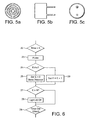
- this routine shows what happens when there is an echo and a distance measurement is possible based on the time elapsed from the ping being sent to the echo being detected. Where this distance is greater than X for N successive polls (30) then the vacancy light 20 is switched on or maintained on (31). If the measurement is not greater than X for N successive polls, the system checks whether the measurement was less than X for N successive polls (32). If it was, this indicates that the parking bay is occupied and the light is switched off or maintained off (33) if, having first checked at 30 that the measurement was not greater than X for N successive polls and then at 32 that it was not less than X for N successive polls, there is no change in status and no change in the parking bay light 20, whether on or off.
- the main controller 4 is preferably provided with an over-ride program that enables main controller 4 to over-ride individual controllers 1 so that they control their respective indicator 7 to show "no vacancies" even when one or more spaces may actually be present in their associated group.
- This enables those in control of a vehicle park to direct vehicles away from congested groups of parking bays, even if there may be the odd vacancy in those groups, to less congested groups, merely by suggesting to drivers reading the indicators that a particular group has no vacancies but that groups further on in the hierarchy do have vacancies.
- the described system has additional utility when combined with a security system for the vehicle park, for example a CCTV system.
- a security system for the vehicle park for example a CCTV system.
- vehicle parks particularly multi-storey vehicle parks in inner city locations late at night, of vehicle theft or so-called "joy-riding" in which vehicles are broken into and driven around, often without actually leaving the vehicle park, frequently causing damage to the vehicle itself, other parked vehicles and the infrastructure of the vehicle park.
- the system preferably additionally includes a warning system (which may be directly linked into the security system, for example to switch on the appropriate CCTV camera or a video recording system linked to the appropriate CCTV camera) that is operable at times (usually late at night) when there are relatively few vehicles present in the vehicle park, the warning system coming into effect whenever a change of status is accepted for any parking bay from "occupied” to "vacant", implying that a previously parked vehicle is moving. Security personnel can then immediately check the appropriate CCTV picture to establish whether this appears to be a legitimate driver having retrieved his vehicle, or a vehicle having been broken into and/or being driven in an erratic manner, and take any action required.
- a warning system which may be directly linked into the security system, for example to switch on the appropriate CCTV camera or a video recording system linked to the appropriate CCTV camera
- Some high value vehicles are fitted with ultrasonic vehicle reversing proximity detectors giving a warning to the driver when the vehicle is getting close to an obstacle; and potentially such ultrasonic devices could interfere with an ultrasonic sensor system employed in a system of the kind disclosed herein. This may cause a false result in the sensor system and may interfere with the reversing system so that the driver fails to receive the correct response and so might hit an obstacle.
- this possibility can easily be overcome by including an additional step in the routines described herein requiring the sensors to "listen" (that is: be empowered to receive a signal) for ultrasonic signals ahead of their time slot for transmitting an ultrasonic ping. Should an ultrasonic signal be detected, the sensor concerned simply vacates its time slot.
- the most suitable prescence/absence detectors are ultrasonic transducers
- other forms of detectors are can be employed for some or all of the detectors in the system, depending on the operating circumstances.
- infra-red detectors may be employed. They are less reliable, as the much higher speed of transmission makes distance measurement unfeasible.
- a reflection or alternatively no reflection can be detected and used to discriminate between occupied and vacant parking spaces, especially if the floor is roughened to reduce any reflection back to the transmitter from the floor.
- a pixelated optical recognition system may be employed. Vehicles have a generally oblong shape with sharp boundaries, whereas the floor, which will be visible when no vehicle is present in a parking space, has an absence of sharp boundaries. This difference may be employed in an object recognition system to discriminate between occupied and vacant parking spaces using an optical system employing relatively few pixels at each parking space, and thus having a relatively low band-width.
- Indicator signs indicating the number of vacant spaces in a group of parking bays may also be used for other purposes, for example by displaying advertising or public service messages in alternation with the indication of numbers of vacant parking bays.
- the system may incorporate an over-ride remote check for individual sensors.
Landscapes
- Physics & Mathematics (AREA)
- General Physics & Mathematics (AREA)
- Traffic Control Systems (AREA)
Abstract
Description
- S =
- the particular time domain slot (see Fig. 2)
- X =
- the distance to the floor minus half the minimum detectable vehicle height
- E =
- the number of "no-echo" samples in successive polls, and
- N =
- a predetermined number of measurement samples or polls before a change of status is accepted by the system.
Claims (16)
- A parking indicator/control system for a vehicle park in which potentially available parking bays for vehicles are arranged in groups of parking bays, the groups being arranged in a hierarchy such that successive groups are located further from an entrance for vehicles than preceding groups; the system being characterised in comprising a controller for each said group, each controller being linked to individual sensors associated with individual parking bays of its group, each of which sensors is adapted to detect the presence or absence of a vehicle in the respective said bay and to communicate such presence or absence to its controller, and each controller being linked to a respective indicator adapted to give an indication of the number of vacant bays at any time in the group to which its controller belongs.
- A system according to Claim 1, further characterised in that the presence/absence sensors linked to a particular indicator are polled in a predetermined sequence to sense the presence or absence of a vehicle in their associated parking bay, thereby avoiding interference between sensors in adjacent parking bays.
- A system according to Claim 2, further characterised in that the presence/absence sensors linked to a particular indicator are periodically synchronised by transmittal of a synchronisation signal from the controller to all sensors associated with that controller.
- A system according to any preceding Claim, further characterised in that said presence/absence sensors comprise ultrasonic transducers adapted to send an ultrasonic pulse train, preferably a single ultrasonic ping, and to detect an echo from that pulse train (ping) resulting from reflection.
- A system according to Claim 3, further characterised in that each presence/absence sensor comprises a single ultrasonic transducer adapted both to transmit an ultrasonic pulse train, preferably a single ultrasonic ping, and to detect the echo from that pulse train (ping) resulting from reflection.
- A system according to any preceding Claim, further characterised in that the several controllers are linked so that each indicator is adapted both to give an indication of the number of vacant bays at any time in the group to which its controller belongs and to give an indication of the total number of vacant bays in groups beyond the said group in the hierarchy.
- A system according to any of Claims 1 to 4, further characterised in that the indicators are linked to a master control provided with an indicator over-ride, enabling more even distribution of vehicles within the vehicle park by over-riding indicators in the most popular groups to cause such indicators to show no vacancies even when one might be present, thereby directing vehicles to less popular parts of the vehicle park.
- A multi-storey vehicle park characterised in being provided with a parking indicator/control system according to any of Claims 1 to 4, wherein each indicator associated with a floor other than the highest floor is arranged to display the number of vacant bays on the particular floor associated with the said indicator, and also at least one of the number of vacant bays on the next higher floor and the total number of vacant bays on all higher floors.
- A multi-level underground vehicle park characterised in being provided with a parking indicator/control system according to any of Claims 1 to 4, wherein each indicator associated with a level other than the lowest level is arranged to display the number of vacant bays on the particular level associated with the said indicator, and also at least one of the number of vacant bays on the next lower level and the total number of vacant bays on all lower levels.
- A vehicle park characterised in being provided with a parking indicator/control system according to Claim 3 or Claim 4, and selected from vehicle parks located in buildings and underground vehicle parks, in which vehicle parks each parking bay has both an associated ceiling and floor, wherein the presence/absence sensors are mounted in the ceiling above respective parking bays and adapted to time the interval between a transmitted pulse train (ping) and its echo resulting from reflection by a vehicle in the said bay or by the floor of the bay, thereby providing an indication whether the said bay is "vacant" or "occupied".
- A vehicle park according to Claim 9 characterised in being provided with a parking indicator/control system according to Claim 2, wherein an existing status, namely one of "vacant" and "occupied", for a particular parking bay, as recognised by the controller associated with that bay, is changed to the other said status only after that other status has been indicated by a predetermined number N of successive polls of the associated sensor.
- A vehicle park according to Claim 11, further characterised in that N is selectable, and optionally is different for different sensors in the system.
- A vehicle park according to Claims 10, 11 or 12, further characterised in that a situation where no echo is detected on polling a particular sensor is treated as an indication that the associated bay is "occupied".
- A vehicle park according to Claims 10, 11 or 12, further characterised in that a situation where a complex multipath signal is detected on polling a particular sensor is treated as an indication that the associated bay is "occupied".
- A vehicle park according to any of Claims 8 to 14, further characterised in that each parking bay has an associated ceiling mounting a vacant lamp, the vacant lamps of parking bays recognised as having a "vacant" status by the associated controller being lit.
- A vehicle park according to any of Claims 8 to 15, further characterised in that a CCTV security system is selectively linked to the parking indicator/control system, whereby an appropriate CCTV camera and/or video recording system is actuated whenever a change of status for a particular parking bay is recognised.
Applications Claiming Priority (2)
| Application Number | Priority Date | Filing Date | Title |
|---|---|---|---|
| GBGB0326135.1A GB0326135D0 (en) | 2003-11-08 | 2003-11-08 | Parking indicator and/or control system |
| GB0326135 | 2003-11-08 |
Publications (2)
| Publication Number | Publication Date |
|---|---|
| EP1530183A2 true EP1530183A2 (en) | 2005-05-11 |
| EP1530183A3 EP1530183A3 (en) | 2006-02-15 |
Family
ID=29726225
Family Applications (1)
| Application Number | Title | Priority Date | Filing Date |
|---|---|---|---|
| EP04256804A Withdrawn EP1530183A3 (en) | 2003-11-08 | 2004-11-04 | Parking indicator and control system |
Country Status (2)
| Country | Link |
|---|---|
| EP (1) | EP1530183A3 (en) |
| GB (2) | GB0326135D0 (en) |
Cited By (8)
| Publication number | Priority date | Publication date | Assignee | Title |
|---|---|---|---|---|
| WO2007000011A1 (en) * | 2005-06-27 | 2007-01-04 | Cds Worldwide Pty Ltd | Access system including parking system and methods |
| SG128498A1 (en) * | 2005-06-14 | 2007-01-30 | Shih Hsiung | Management method and system for a parking lot |
| EP2418634A1 (en) * | 2010-08-10 | 2012-02-15 | Circontrol S.A. | Device and method for detecting the presence of a vehicle in a parking space |
| CN103325279A (en) * | 2013-07-08 | 2013-09-25 | 无锡商业职业技术学院 | Parking position real-time monitoring system |
| EP2709083A2 (en) | 2012-09-12 | 2014-03-19 | Moises Jaime Rodrich | Method and device for detecting presence of a vehicle in a parking space |
| US8830088B2 (en) | 2012-12-18 | 2014-09-09 | TCS International, Inc. | Zone controller |
| CN107705387A (en) * | 2017-01-12 | 2018-02-16 | 西安艾润物联网技术服务有限责任公司 | Pass in and out car data processing method and parking lot controller |
| EP3462429A1 (en) * | 2017-09-29 | 2019-04-03 | Deutsche Telekom AG | Augmented reality parking system and method thereof |
Families Citing this family (1)
| Publication number | Priority date | Publication date | Assignee | Title |
|---|---|---|---|---|
| US10665100B2 (en) * | 2018-02-15 | 2020-05-26 | Verizon Patent And Licensing Inc. | Systems and methods for managing and tracking space availability |
Family Cites Families (13)
| Publication number | Priority date | Publication date | Assignee | Title |
|---|---|---|---|---|
| US3376547A (en) * | 1964-10-20 | 1968-04-02 | Gen Signal Corp | Parking area scanning system |
| JPH01173200A (en) * | 1987-12-28 | 1989-07-07 | Stanley Electric Co Ltd | parking lot display system |
| JPH0218700A (en) * | 1988-07-06 | 1990-01-22 | Hiromasa Takeuchi | Control system for parking lot |
| JPH04169999A (en) * | 1990-11-01 | 1992-06-17 | Matsushita Electric Works Ltd | Parking system device |
| US5432508A (en) * | 1992-09-17 | 1995-07-11 | Jackson; Wayne B. | Technique for facilitating and monitoring vehicle parking |
| JPH06151094A (en) * | 1992-11-11 | 1994-05-31 | Mitsubishi Heavy Ind Ltd | Plasma generation accelerator |
| JP2500894B2 (en) * | 1992-11-16 | 1996-05-29 | 株式会社石川製作所 | Parking condition detection system |
| JP3022156B2 (en) * | 1994-05-10 | 2000-03-15 | 松下電工株式会社 | Parking lot control system equipment |
| GB2320970B (en) * | 1994-09-30 | 1998-08-19 | Wigley K C & Co Ltd | Monitoring of vehicle parking |
| JPH1173200A (en) * | 1997-08-29 | 1999-03-16 | Dainippon Printing Co Ltd | Audio signal encoding method and computer-readable recording medium |
| JP3558058B2 (en) * | 2000-08-11 | 2004-08-25 | 丸鷹株式会社 | Automatic guidance method and outdoor guidance device in outdoor parking lot |
| JP2002342896A (en) * | 2001-05-21 | 2002-11-29 | Seiko Epson Corp | Parking Information System and Parking Information Program |
| WO2003000520A1 (en) * | 2001-06-21 | 2003-01-03 | Tis, Inc. | Parking guidance and vehicle control system |
-
2003
- 2003-11-08 GB GBGB0326135.1A patent/GB0326135D0/en not_active Ceased
-
2004
- 2004-11-04 EP EP04256804A patent/EP1530183A3/en not_active Withdrawn
- 2004-11-04 GB GB0424415A patent/GB2408132B/en not_active Expired - Fee Related
Cited By (13)
| Publication number | Priority date | Publication date | Assignee | Title |
|---|---|---|---|---|
| SG128498A1 (en) * | 2005-06-14 | 2007-01-30 | Shih Hsiung | Management method and system for a parking lot |
| WO2007000011A1 (en) * | 2005-06-27 | 2007-01-04 | Cds Worldwide Pty Ltd | Access system including parking system and methods |
| EP2418634A1 (en) * | 2010-08-10 | 2012-02-15 | Circontrol S.A. | Device and method for detecting the presence of a vehicle in a parking space |
| ES2388291A1 (en) * | 2010-08-10 | 2012-10-11 | Circontrol, S.A. | Device and method for detecting the presence of a vehicle in a parking space |
| US20140112101A1 (en) * | 2012-09-12 | 2014-04-24 | Moises Jaime RODRICH | Method and device for detecting presence of vehicle in parking space |
| EP2709083A2 (en) | 2012-09-12 | 2014-03-19 | Moises Jaime Rodrich | Method and device for detecting presence of a vehicle in a parking space |
| US9213098B2 (en) | 2012-09-12 | 2015-12-15 | Moises Jaime RODRICH | Method and device for detecting presence of vehicle in parking space |
| US9536430B2 (en) | 2012-09-12 | 2017-01-03 | Moises Jaime RODRICH | Method and device for detecting presence of vehicle in parking space |
| US8830088B2 (en) | 2012-12-18 | 2014-09-09 | TCS International, Inc. | Zone controller |
| WO2014099903A3 (en) * | 2012-12-18 | 2014-12-18 | TCS International, Inc. | Zone controller |
| CN103325279A (en) * | 2013-07-08 | 2013-09-25 | 无锡商业职业技术学院 | Parking position real-time monitoring system |
| CN107705387A (en) * | 2017-01-12 | 2018-02-16 | 西安艾润物联网技术服务有限责任公司 | Pass in and out car data processing method and parking lot controller |
| EP3462429A1 (en) * | 2017-09-29 | 2019-04-03 | Deutsche Telekom AG | Augmented reality parking system and method thereof |
Also Published As
| Publication number | Publication date |
|---|---|
| EP1530183A3 (en) | 2006-02-15 |
| GB0424415D0 (en) | 2004-12-08 |
| GB2408132B (en) | 2006-04-26 |
| GB0326135D0 (en) | 2003-12-17 |
| GB2408132A (en) | 2005-05-18 |
| GB2408132A9 (en) | 2005-06-16 |
Similar Documents
| Publication | Publication Date | Title |
|---|---|---|
| AU2014202297B2 (en) | Route computation for navigation system using data exchanged with ticket vending machines | |
| JP4262919B2 (en) | Parking guidance and management system | |
| US5613216A (en) | Self-contained vehicle proximity triggered resettable timer and mass transit rider information system | |
| US6229455B1 (en) | Vehicle-detecting unit for use with electronic parking meter | |
| JP4708666B2 (en) | Electronic parking meter system | |
| US3166732A (en) | Vehicular parking systems | |
| US20060109104A1 (en) | Method and apparatus reporting a vehicular sensor waveform in a wireless vehicular sensor network | |
| US7701361B2 (en) | Parking information sensing device and providing method thereof | |
| KR100831935B1 (en) | Intelligent Vehicle Safe Driving Method and System Using Adaptive Communication Technology | |
| GB2408132A (en) | Parking Control System | |
| WO2003000520A1 (en) | Parking guidance and vehicle control system | |
| US9595194B1 (en) | Sensor system and algorithm for reliable truck stop parking indications | |
| JP2005301884A (en) | Roundabout vehicle information system | |
| CA2679815A1 (en) | Intelligent vehicular speed control system | |
| US20140005961A1 (en) | Occupancy sensing | |
| KR100828088B1 (en) | Billboard combined real-time parking guidance system and its operation method. | |
| KR20100074747A (en) | Park managing system using wireless network | |
| KR101527206B1 (en) | System and method for managing the admittance to parking place | |
| JP4707062B2 (en) | Traffic jam occurrence prediction device and program | |
| JP3073812B2 (en) | Parking system | |
| KR101776861B1 (en) | A setting control system for parking detection means using wireless communication | |
| JP2822697B2 (en) | Parking meter system | |
| GB2415078A (en) | Method and system for managing a parking lot. | |
| JPH04171600A (en) | car management system | |
| US6281809B1 (en) | Vehicle detector with audible call signal indicator |
Legal Events
| Date | Code | Title | Description |
|---|---|---|---|
| PUAI | Public reference made under article 153(3) epc to a published international application that has entered the european phase |
Free format text: ORIGINAL CODE: 0009012 |
|
| AK | Designated contracting states |
Kind code of ref document: A2 Designated state(s): AT BE BG CH CY CZ DE DK EE ES FI FR GB GR HU IE IS IT LI LU MC NL PL PT RO SE SI SK TR |
|
| AX | Request for extension of the european patent |
Extension state: AL HR LT LV MK YU |
|
| PUAL | Search report despatched |
Free format text: ORIGINAL CODE: 0009013 |
|
| AK | Designated contracting states |
Kind code of ref document: A3 Designated state(s): AT BE BG CH CY CZ DE DK EE ES FI FR GB GR HU IE IS IT LI LU MC NL PL PT RO SE SI SK TR |
|
| AX | Request for extension of the european patent |
Extension state: AL HR LT LV MK YU |
|
| 17P | Request for examination filed |
Effective date: 20060501 |
|
| AKX | Designation fees paid |
Designated state(s): AT BE BG CH CY CZ DE DK EE ES FI FR GB GR HU IE IS IT LI LU MC NL PL PT RO SE SI SK TR |
|
| 17Q | First examination report despatched |
Effective date: 20060602 |
|
| GRAP | Despatch of communication of intention to grant a patent |
Free format text: ORIGINAL CODE: EPIDOSNIGR1 |
|
| GRAS | Grant fee paid |
Free format text: ORIGINAL CODE: EPIDOSNIGR3 |
|
| RBV | Designated contracting states (corrected) |
Designated state(s): AT BE BG CH CY CZ DE DK EE ES FI FR GR HU IE IS IT LI LU MC NL PL PT RO SE SI SK TR |
|
| STAA | Information on the status of an ep patent application or granted ep patent |
Free format text: STATUS: THE APPLICATION IS DEEMED TO BE WITHDRAWN |
|
| 18D | Application deemed to be withdrawn |
Effective date: 20090603 |