EP1530163A2 - CT image producing method and x-ray CT apparatus - Google Patents
CT image producing method and x-ray CT apparatus Download PDFInfo
- Publication number
- EP1530163A2 EP1530163A2 EP04256827A EP04256827A EP1530163A2 EP 1530163 A2 EP1530163 A2 EP 1530163A2 EP 04256827 A EP04256827 A EP 04256827A EP 04256827 A EP04256827 A EP 04256827A EP 1530163 A2 EP1530163 A2 EP 1530163A2
- Authority
- EP
- European Patent Office
- Prior art keywords
- ray
- data
- projection
- image
- view
- Prior art date
- Legal status (The legal status is an assumption and is not a legal conclusion. Google has not performed a legal analysis and makes no representation as to the accuracy of the status listed.)
- Withdrawn
Links
Images


Classifications
-
- A—HUMAN NECESSITIES
- A61—MEDICAL OR VETERINARY SCIENCE; HYGIENE
- A61B—DIAGNOSIS; SURGERY; IDENTIFICATION
- A61B6/00—Apparatus or devices for radiation diagnosis; Apparatus or devices for radiation diagnosis combined with radiation therapy equipment
- A61B6/02—Arrangements for diagnosis sequentially in different planes; Stereoscopic radiation diagnosis
- A61B6/03—Computed tomography [CT]
-
- G—PHYSICS
- G06—COMPUTING OR CALCULATING; COUNTING
- G06T—IMAGE DATA PROCESSING OR GENERATION, IN GENERAL
- G06T12/00—Tomographic reconstruction from projections
- G06T12/10—Image preprocessing, e.g. calibration, positioning of sources or scatter correction
-
- A—HUMAN NECESSITIES
- A61—MEDICAL OR VETERINARY SCIENCE; HYGIENE
- A61B—DIAGNOSIS; SURGERY; IDENTIFICATION
- A61B6/00—Apparatus or devices for radiation diagnosis; Apparatus or devices for radiation diagnosis combined with radiation therapy equipment
- A61B6/02—Arrangements for diagnosis sequentially in different planes; Stereoscopic radiation diagnosis
- A61B6/027—Arrangements for diagnosis sequentially in different planes; Stereoscopic radiation diagnosis characterised by the use of a particular data acquisition trajectory, e.g. helical or spiral
-
- G—PHYSICS
- G06—COMPUTING OR CALCULATING; COUNTING
- G06T—IMAGE DATA PROCESSING OR GENERATION, IN GENERAL
- G06T2211/00—Image generation
- G06T2211/40—Computed tomography
- G06T2211/412—Dynamic
Definitions
- the present invention relates to a CT image producing method and an X-ray CT (computed tomography) apparatus, and more particularly to a CT image producing method and an X-ray CT apparatus for scanning a periodically moving subject to be imaged using a multi-row detector, and producing a CT image at a desired phase with reduced cone-beam artifacts.
- a conventional multi-sector reconstruction technique which involves scanning a heart over a plurality of cardiac cycles, gathering data at a desired cardiac phase from among the obtained data to create a data set needed in image reconstruction, and reconstructing a CT image at the desired cardiac phase from the data set (see Japanese Patent Application Laid Open No. 2003-052688 and "All about Multi-row Detector Helical CT,” edited by Mutsumasa TAKAHASHI and Akihiko ARAKAWA, Kanehara & Co., Ltd., (February 1, 2002) pp. 86 ⁇ 89 ('Image Reconstruction By Electrocardiographic Synchronization,' written by Seiki HAMADA, Hironobu NAKAMURA, and Hiroaki NAITO)) for example.
- the reconstruction plane lies at a position away from the center of the multi-row detector (the center being the position straight below the X-ray tube)
- the X-ray beam is actually not parallel to the reconstruction plane, resulting in cone-beam artifacts in the CT image.
- the present invention therefore seeks to provide a CT image producing method and an X-ray CT apparatus for scanning a periodically moving subject to be imaged using a multi-row detector, and producing a CT image at a desired phase with reduced cone-beam artifacts.
- the present invention provides a CT image producing method characterized in comprising: scanning a periodically moving subject to be imaged over a plurality of cycles while making relative rotation of at least one of an X-ray tube and a multi-row detector around said subject to be imaged; extracting projection data collected in the same phase range in said plurality of cycles, said projection data being collected at a projection point onto which a pixel on a reconstruction plane is projected on a multi-row detector plane in a direction of X-ray transmission; and producing a CT image based on said extracted projection data.
- relative rotation includes: for a subject to be imaged placed in between the X-ray tube and multi-row detector, rotating at least one of the X-ray tube and multi-row detector around the subject to be imaged without rotating the subject to be imaged; rotating the subject to be imaged around its axis without rotating the X-ray tube and multi-row detector; and rotating the subject to be imaged around its axis and counter-rotating at least one of the X-ray tube and multi-row detector around the subject to be imaged.
- a CT image of a periodically moving subject to be imaged can be produced at a desired phase.
- the CT image is produced by extracting projection data of a detector row and channel upon which an X-ray beam passing through a pixel on a reconstruction plane impinges, cone-beam artifacts can be reduced.
- the present invention provides a CT image producing method characterized in comprising: scanning a periodically moving subject to be imaged over a plurality of cycles while making relative rotation of at least one of an X-ray tube and a multi-row detector around said subject to be imaged and making relative rectilinear motion of said X-ray tube and multi-row detector with respect to said subject to be imaged; extracting projection data collected in the same phase range in said plurality of cycles, said projection data being collected at a projection point onto which a pixel on a reconstruction plane is projected on a multi-row detector plane in a direction of X-ray transmission; and producing a CT image based on said extracted projection data.
- the term "relative rectilinear motion” includes: for a subject to be imaged placed in between the X-ray tube and multi-row detector, rectilinearly moving the subject to be imaged (or the table on which the subject to be imaged is laid) without rectilinearly moving the X-ray tube and multi-row detector; rectilinearly moving the X-ray tube and multi-row detector without rectilinearly moving the subject to be imaged (or the table on which the subject to be imaged is laid); and rectilinearly moving the subject to be imaged (or the table on which the subject to be imaged is laid) and rectilinearly moving the X-ray tube and multi-row detector in the opposite direction.
- a CT image of a periodically moving subject to be imaged can be produced at a desired phase.
- the CT image is produced by extracting projection data of a detector row and channel upon which an X-ray beam passing through a pixel on a reconstruction plane impinges, cone-beam artifacts can be reduced.
- the present invention provides the CT image producing method having the aforementioned configuration, characterized in comprising: when a view range V needed in image reconstruction is divided into N segments from first through N-th segments (N ⁇ 2), repeating N times the collection of data for one segment in one cycle.
- the imaging time required is of only a period corresponding to N cycles.
- projection data of an adjacent segment can be collected for each cycle of the subject to be imaged.
- the present invention provides the CT image producing method having the aforementioned configuration, characterized in comprising: producing a CT image by a three-dimensional image reconstruction technique.
- Known three-dimensional image reconstruction techniques include the Feldkamp method and the weighted Feldkamp method.
- the present invention provides the X-ray CT imaging method having the aforementioned configuration, characterized in that said three-dimensional image reconstruction technique is a three-dimensional backprojection method comprising: extracting projection data corresponding to a projection line formed by projecting one line or a plurality of parallel lines at spacings of a plurality of pixels on a reconstruction plane onto a multi-row detector plane in a direction of X-ray transmission; generating projection line data by multiplying said extracted projection data by a cone beam reconstruction weight; generating back-projected line data by filtering said projection line data; determining back-projected pixel data of each pixel on the reconstruction plane based on said back-projected line data; and determining back-projected data by adding the back-projected pixel data on a pixel-by-pixel basis for all views used in image reconstruction.
- said three-dimensional image reconstruction technique is a three-dimensional backprojection method comprising: extracting projection data corresponding to a projection line formed by projecting one line or a plurality of parallel lines
- the volume of calculation can be significantly reduced.
- the angle between the line and direction of X-ray transmission is no less than about 45°, accuracy reduction can be prevented.
- the present invention provides the CT image producing method having the aforementioned configuration, characterized in that: the subject to be imaged is a heart, and the phase of the cyclic motion is detected based on electrocardiographic signals.
- a CT image of the heart at a desired phase can be suitably produced.
- the present invention provides an X-ray CT apparatus characterized in comprising: an X-ray tube; a multi-row detector; scanning means for scanning a subject to be imaged over a plurality of cycles while rotating at least one of said X-ray tube and multi-row detector around said subject to be imaged; and image reconstructing means for extracting projection data collected in the same phase range in said plurality of cycles, said projection data being collected at a projection point onto which a pixel on a reconstruction plane is projected on a multi-row detector plane in a direction of X-ray transmission, and producing a CT image based on said extracted projection data.
- the CT image producing method of the first aspect can be suitably implemented.
- the present invention provides an X-ray CT apparatus characterized in comprising: an X-ray tube; a multi-row detector; scanning means for scanning a subject to be imaged over a plurality of cycles while rotating at least one of said X-ray tube and multi-row detector around said subject to be imaged and making relative rectilinear motion of said X-ray tube and multi-row detector with respect to said subject to be imaged; and image reconstructing means for extracting projection data collected in the same phase range in said plurality of cycles, said projection data being collected at a projection point onto which a pixel on a reconstruction plane is projected on a multi-row detector plane in a direction of X-ray transmission, and producing a CT image based on said extracted projection data.
- the CT image producing method of the second aspect can be suitably implemented.
- the present invention provides the X-ray CT apparatus having the aforementioned configuration, characterized in that: when a view range V needed in image reconstruction is divided into N segments from first through N-th segments (N ⁇ 2), said scanning means repeats N times the collection of data for one segment in one cycle.
- the CT image producing method of the third aspect can be suitably implemented.
- the CT image producing method of the fourth aspect can be suitably implemented.
- the CT image producing method of the fifth aspect can be suitably implemented.
- the present invention provides the X-ray CT apparatus having the aforementioned configuration, characterized in that: said image reconstructing means produces a CT image by a three-dimensional image reconstruction technique.
- the CT image producing method of the sixth aspect can be suitably implemented.
- the present invention provides the X-ray CT apparatus having the aforementioned configuration, characterized in that said three-dimensional image reconstruction technique is a three-dimensional back-projection method comprising: extracting projection data corresponding to a projection line formed by projecting one line or a plurality of parallel lines at spacings of a plurality of pixels on a reconstruction plane onto a multi-row detector plane in a direction of X-ray transmission; generating projection line data by multiplying said extracted projection data by a cone beam reconstruction weight; generating back-projected line data by filtering said projection line data; determining back-projected pixel data of each pixel on the reconstruction plane based on said back-projected line data; and determining back-projected data by adding the back-projected pixel data on a pixel-by-pixel basis for all views used in image reconstruction.
- said three-dimensional image reconstruction technique is a three-dimensional back-projection method comprising: extracting projection data corresponding to a projection line formed by projecting one line or a plurality of parallel
- the CT image producing method of the seventh aspect can be suitably implemented.
- the CT image producing method of the eighth aspect can be suitably implemented.
- the present invention provides the X-ray CT apparatus having the aforementioned configuration, characterized in further comprising: an electrocardiograph for detecting the phase of cyclic motion of a heart.
- the CT image producing method of the ninth aspect can be suitably implemented.
- a periodically moving subject to be imaged can be scanned using a multi-row detector to produce a CT image at a desired phase with reduced cone-beam artifacts.
- the CT image producing method and X-ray CT apparatus of the present invention are applicable for producing a CT image of the heart at a desired phase.
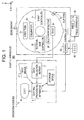
- Figure 1 is a block diagram showing the configuration of an X-ray CT apparatus 100 of Example 1.
- the X-ray CT apparatus 100 comprises an operation console 1, a table apparatus 10, a scan gantry 20, and an electrocardiograph (ECG) 40.
- ECG electrocardiograph
- the operation console 1 comprises an input device 2 for accepting inputs by a human operator, a central processing apparatus 3 for executing image reconstruction processing etc., a data collection buffer 5 for collecting projection data acquired at the scan gantry 20, a CRT 6 for displaying a CT image reconstructed from the projection data, and a storage device 7 for storing programs, data, and X-ray CT images.
- the table apparatus 10 comprises a table 12 for laying thereon a subject to be imaged and transporting the subject into/out of a bore (cavity portion) of the scan gantry 20.
- the table 12 is vertically moved and rectilinearly moved by a motor incorporated in the table apparatus 10.
- the scan gantry 20 comprises an X-ray tube 21, an X-ray controller 22, a collimator 23, a multi-row detector 24, a DAS (data acquisition system) 25, a rotator-side controller 26 for controlling the X-ray controller 22, collimator 23 and DAS 25, an overall controller 29 for communicating control signals etc. with the operation console 1 and imaging table 10, and a slip ring 30.
- Figures 2 and 3 are explanatory diagrams of the X-ray tube 21 and multi-row detector 24.
- the X-ray tube 21 and multi-row detector 24 rotate around a center of rotation IC. Representing the direction of rectilinear motion of the table 12 as a z-direction, a direction perpendicular to the upper surface of the table 12 as a y-direction, and a direction orthogonal to the z- and y-directions as an x-direction, a plane of rotation of the X-ray tube 21 and multi-row detector 24 is an x-y plane.
- the X-ray tube 21 generates an X-ray beam CB generally referred to as a cone beam.
- a view angle view 0° is defined.
- Figure 4 is a flow chart showing processing of the multi-sector reconstruction technique using the X-ray CT apparatus 100.
- Step S1 the operator inputs via the input device 2 a range of table movement, a speed of table motion, a time width ⁇ e of a desired phase range, and a lag time ⁇ a with respect to an R-wave.
- Step S2 the central processing apparatus 3 detects a cardiac cycle T by the electrocardiograph 40.
- the rectilinear motion position z is obtained by an encoder counting a z-position pulse, converted into a z-coordinate at the overall controller 29, passed via the slip ring 30, and appended as z-coordinate information to the projection data from the DAS 25.
- Figure 5 shows a format of the projection data at a certain view appended with the z-coordinate information.
- Step S5 the projection data D0( z , view, j, i ) is subjected to pre-processing (offset correction, log correction, X-ray dose correction and sensitivity correction).
- Step S6 the pre-processed projection data D0( z , view, j, i ) is subjected to three-dimensional back-projection processing to determine back-projected data D3( x , y ).
- Step S7 the back-projected data D3( x, y ) is subjected to post-processing to obtain a CT image.
- the multi-sector reconstruction technique divides a view range needed in image reconstruction into N segments from first through N-th segments (N ⁇ 2).
- the projection data in that data set all represent a phase range having a time width ⁇ e from the time delayed by ⁇ a with reference to an R-wave.
- FIG 8 is a flow chart showing details of the three-dimensional backprojection processing (Step S6 in Figure 4).
- one view is taken as a view of interest from a data set obtained at Step S4 of Figure 4.
- projection data Dr corresponding to a plurality of parallel lines at spacings of a plurality of pixels on a reconstruction plane P are extracted from the projection data D0( z , view , j, i ) at the view of interest.
- Figure 9 exemplarily shows a plurality of parallel lines L0 ⁇ L8 on the reconstruction plane P.
- the number of lines is 1/64 ⁇ 1/2 of the maximum number of pixels in the reconstruction plane in a direction orthogonal to the lines. For example, if the number of pixels in the reconstruction plane P is 512 ⁇ 512, the number of lines is nine.
- the line direction is defined as the x-direction for -45° ⁇ view ⁇ 45° (or a view angle range mainly including the range and also including its vicinity) and 135° ⁇ view ⁇ 225° (or a view angle range mainly including the range and also including its vicinity).
- the line direction is defined as the y-direction for 45° ⁇ view ⁇ 135° (or a view angle range mainly including the range and also including its vicinity) and 225° ⁇ view ⁇ 315° (or a view angle range mainly including the range and also including its vicinity).
- a projection plane pp is assumed to pass through the center of rotation IC and be parallel to the lines L0 ⁇ L8.
- Figure 10 shows lines T0 ⁇ T8 formed by projecting the plurality of parallel lines L0 ⁇ L8 on the reconstruction plane P onto a detector plane dp in a direction of X-ray transmission.
- the direction of X-ray transmission is determined depending upon the geometry of the X-ray tube 21, multi-row detector 24 and lines L0 ⁇ L8.
- the projection data Dr corresponding to the lines L0 ⁇ L8 can be obtained by extracting projection data at the detector row j and channel i corresponding to the lines T0 ⁇ T8 projected onto the detector plane dp.
- Step R3 the projection data Dr of the lines L0' ⁇ L8' on the projection plane pp are multiplied by a cone beam reconstruction weight to generate projection line data Dp on the projection plane pp as shown in Figure 12.
- the cone beam reconstruction weight is ( r 1/ r 0) 2 , where r 0 is the distance from the focal spot of the X-ray tube 21 to the j -th detector row and i -th channel of the multi-row detector 24 corresponding to projection data Dr, and r 1 is the distance from the focal spot of the X-ray tube 21 to a point on the reconstruction plane P corresponding to the projection data Dr.
- the projection line data Dp on the projection plane pp are filtered. Specifically, the projection line data Dp on the projection plane pp are subjected to FFT, multiplied by a filter function (reconstruction function), and subjected to inverse FFT to generate image back-projected line data Df on the projection plane pp as shown in Figure 13.
- Step R5 the back-projected line data Df on the projection plane pp is interpolated in the line direction to generate high-density back-projected line data Dh on the projection plane pp as shown in Figure 14.
- the data density of the high-density back-projected line data Dh on the projection plane pp is 8 ⁇ 32 times the maximum number of pixels in the reconstruction plane P in the line direction. For example, if the factor is 16 and the number of pixels in the reconstruction plane P is 512 ⁇ 512, the data density is 8,192 points/line.
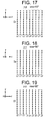
- Step R6 the high-density back-projected line data Dh on the projection plane pp are sampled and interpolated/extrapolated, if necessary, to generate back-projected pixel data D2 for pixels on the lines L0 ⁇ L8 on the reconstruction plane P, as shown in Figure 15.
- the high-density back-projected line data Dh are sampled and interpolated/extrapolated to generate back-projection data D2 for pixels in between the lines L0 ⁇ L8, as shown in Figure 16.
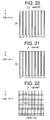
- the interpolation/extrapolation is conducted based on the back-projected pixel data D2 for pixels on the lines L0 ⁇ L8 on the reconstruction plane P to generate back-projected pixel data D2 for pixels in between the lines L0 - L8.
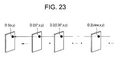
- Step R8 the back-projected pixel data D2 shown in Figure 16 or 22 are added on a pixel-by-pixel basis, as shown in Figure 23.
- Step R9 Steps R1 ⁇ R8 are repeated for all views in the data set obtained at Step S4 of Figure 4 to obtain back-projected data D3( x , y ).
- a CT image can be produced at a desired cardiac phase. Moreover, since the CT image is produced by extracting projection data of a detector row j and channel i upon which an X-ray beam passing through a pixel on a reconstruction plane P impinges, cone-beam artifacts can be reduced.
- Example 1 While in Example 1, only projection data corresponding to the lines L0 ⁇ L8 on the reconstruction plane P are extracted from the data set, projection data corresponding to all pixels on the reconstruction plane P may be extracted to reconstruct a CT image.
- the technique for image reconstruction may be a conventionally known three-dimensional image reconstruction technique according to the Feldkamp method.
- three-dimensional image reconstruction techniques proposed in Japanese Patent Application Nos. 2002-066420, 2002-147061, 2002-147231, 2002-235561, 2002-235662, 2002-267833, 2002-322756 and 2002-338947 may be employed.
Landscapes
- Engineering & Computer Science (AREA)
- Health & Medical Sciences (AREA)
- Life Sciences & Earth Sciences (AREA)
- Physics & Mathematics (AREA)
- Medical Informatics (AREA)
- General Physics & Mathematics (AREA)
- Theoretical Computer Science (AREA)
- Optics & Photonics (AREA)
- Heart & Thoracic Surgery (AREA)
- Nuclear Medicine, Radiotherapy & Molecular Imaging (AREA)
- Biophysics (AREA)
- Pathology (AREA)
- Radiology & Medical Imaging (AREA)
- Biomedical Technology (AREA)
- High Energy & Nuclear Physics (AREA)
- Molecular Biology (AREA)
- Surgery (AREA)
- Animal Behavior & Ethology (AREA)
- General Health & Medical Sciences (AREA)
- Public Health (AREA)
- Veterinary Medicine (AREA)
- Apparatus For Radiation Diagnosis (AREA)
- Analysing Materials By The Use Of Radiation (AREA)
Abstract
Description
Claims (10)
- A CT image producing method comprising the steps of: scanning a periodically moving subject to be imaged over a plurality of cycles while making relative rotation of at least one of an X-ray tube (21) and a multi-row detector (24) around said subject to be imaged; extracting projection data collected in the same phase range in said plurality of cycles, said projection data being collected at a projection point onto which a pixel on a reconstruction plane is projected on a multi-row detector plane in a direction of X-ray transmission; and producing a CT image based on said extracted projection data.
- An X-ray CT apparatus (100) comprising: an X-ray tube (21); a multi-row detector (24); a scanning device (20) for scanning a subject to be imaged over a plurality of cycles while making relative rotation of at least one of said X-ray tube and multi-row detector around said subject to be imaged; and an image reconstructing device (3) for extracting projection data collected in the same phase range in said plurality of cycles, said projection data being collected at a projection point onto which a pixel on a reconstruction plane is projected on a multi-row detector plane in a direction of X-ray transmission, and producing a CT image based on said extracted projection data.
- An X-ray CT apparatus (100) comprising: an X-ray tube (21); a multi-row detector (24); a scanning device (20) for scanning a subject to be imaged over a plurality of cycles while making relative rotation of at least one of said X-ray tube and multi-row detector around said subject to be imaged and making relative rectilinear motion of said X-ray tube and multi-row detector with respect to said subject to be imaged; and an image reconstructing device (3) for extracting projection data collected in the same phase range in said plurality of cycles, said projection data being collected at a projection point onto which a pixel on a reconstruction plane is projected on a multi-row detector plane in a direction of X-ray transmission, and producing a CT image based on said extracted projection data.
- The X-ray CT apparatus (100) of claim 2 or 3, wherein: when a view range V needed in image reconstruction is divided into N segments from first through N-th segments (N ≥ 2), said scanning device repeats N times the collection of data for one segment in one cycle.
- The X-ray CT apparatus (100) of claim 4, wherein: representing the cycle of motion of the subject to be imaged as T, the time width of said phase range as τe, and the cycle of rotation of the X-ray tube (21) and multi-row detector (24) as Ts, said scanning device (20) defines:
- The X-ray CT apparatus (100) of any one of claim 2 ― 5, wherein: the view range V needed in image reconstruction is V = (180° + fan beam angle).
- The X-ray CT apparatus (100) of any one of claims 2 ― 6, wherein: said image reconstructing device (3) produces a CT image by a three-dimensional image reconstruction technique.
- The X-ray CT apparatus (100) of claim 7, wherein said three-dimensional image reconstruction technique is a three-dimensional back-projection method comprising: extracting projection data corresponding to a projection line formed by projecting one line or a plurality of parallel lines at spacings of a plurality of pixels on a reconstruction plane onto a multi-row detector plane in a direction of X-ray transmission; generating projection line data by multiplying said extracted projection data by a cone beam reconstruction weight; generating back-projected line data by filtering said projection line data; determining back-projected pixel data of each pixel on the reconstruction field based on said back-projected line data; and determining back-projected data by adding the back-projected pixel data on a pixel-by-pixel basis for all views used in image reconstruction.
- The X-ray CT apparatus (100) of claim 8, wherein: representing a direction perpendicular to a plane of rotation of the X-ray tube and multi-row detector or a direction of rectilinear motion of a helical scan as a z-direction, a direction of the center axis of the X-ray beam at a view angle view = 0° as a y-direction, and a direction orthogonal to the z- and y-directions as an x-direction, the line direction is defined as the x-direction for -45° ≤ view < 45° or a view angle range mainly including the range and also including its vicinity and 135° ≤ view < 225° or a view angle range mainly including the range and also including its vicinity, and the line direction is defined as the y-direction for 45° ≤ view < 135° or a view angle range mainly including the range and also including its vicinity and 225° ≤ view < 315° or a view angle range mainly including the range and also including its vicinity.
- The X-ray CT apparatus (100) of any one of claims 2 ― 9, further comprising: an electrocardiograph (40) for detecting the phase of cyclic motion of a heart.
Applications Claiming Priority (2)
| Application Number | Priority Date | Filing Date | Title |
|---|---|---|---|
| JP2003373871A JP2005137390A (en) | 2003-11-04 | 2003-11-04 | CT image generation method and X-ray CT apparatus |
| JP2003373871 | 2003-11-04 |
Publications (2)
| Publication Number | Publication Date |
|---|---|
| EP1530163A2 true EP1530163A2 (en) | 2005-05-11 |
| EP1530163A3 EP1530163A3 (en) | 2010-07-21 |
Family
ID=34431239
Family Applications (1)
| Application Number | Title | Priority Date | Filing Date |
|---|---|---|---|
| EP04256827A Withdrawn EP1530163A3 (en) | 2003-11-04 | 2004-11-04 | CT image producing method and x-ray CT apparatus |
Country Status (5)
| Country | Link |
|---|---|
| US (1) | US20050094760A1 (en) |
| EP (1) | EP1530163A3 (en) |
| JP (1) | JP2005137390A (en) |
| KR (1) | KR20050042727A (en) |
| CN (1) | CN1613427A (en) |
Cited By (2)
| Publication number | Priority date | Publication date | Assignee | Title |
|---|---|---|---|---|
| EP1555633A3 (en) * | 2003-12-22 | 2005-11-09 | GE Medical Systems Global Technology Company LLC | Multi-positional CT image producing method and x-ray CT apparatus |
| NL1033652C2 (en) * | 2006-04-06 | 2008-12-15 | Ge Med Sys Global Tech Co Llc | X-ray CT equipment. |
Families Citing this family (10)
| Publication number | Priority date | Publication date | Assignee | Title |
|---|---|---|---|---|
| JP4025530B2 (en) * | 2001-10-24 | 2007-12-19 | 株式会社日立メディコ | X-ray CT system |
| JP4222930B2 (en) * | 2003-12-10 | 2009-02-12 | ジーイー・メディカル・システムズ・グローバル・テクノロジー・カンパニー・エルエルシー | Three-dimensional backprojection method and apparatus and X-ray CT apparatus |
| WO2005072613A1 (en) * | 2004-02-02 | 2005-08-11 | Hitachi Medical Corporation | Laminographic device and method |
| JP3930493B2 (en) * | 2004-05-17 | 2007-06-13 | ジーイー・メディカル・システムズ・グローバル・テクノロジー・カンパニー・エルエルシー | Image processing method, image processing apparatus, and X-ray CT apparatus |
| JP4639143B2 (en) | 2005-11-30 | 2011-02-23 | ジーイー・メディカル・システムズ・グローバル・テクノロジー・カンパニー・エルエルシー | X-ray CT apparatus and control method thereof |
| WO2008018510A1 (en) * | 2006-08-08 | 2008-02-14 | Shimadzu Corporation | Radiation imaging device |
| JP5525706B2 (en) * | 2007-07-25 | 2014-06-18 | 株式会社東芝 | X-ray computed tomography system |
| CN101887591B (en) * | 2010-06-24 | 2011-09-14 | 西北工业大学 | Cone beam CT (computed tomography) fast reconstruction method based on rectangular bounding box |
| JP6233980B2 (en) * | 2013-02-21 | 2017-11-22 | 株式会社日立製作所 | X-ray CT apparatus and image reconstruction method |
| CN107358641A (en) * | 2017-07-06 | 2017-11-17 | 林嘉恒 | Prime number spiral scanning method and system |
Family Cites Families (13)
| Publication number | Priority date | Publication date | Assignee | Title |
|---|---|---|---|---|
| US5838756A (en) * | 1996-01-08 | 1998-11-17 | Kabushiki Kaisha Toshiba | Radiation computed tomography apparatus |
| US6233478B1 (en) * | 1998-09-28 | 2001-05-15 | Advanced Research & Technology Institute | Apparatus and method for constructing computed tomography image slices of an object undergoing cyclic motion |
| US6639965B1 (en) * | 1999-09-30 | 2003-10-28 | General Electric Company | Methods and apparatus for cardiac imaging with conventional computed tomography |
| US6522712B1 (en) * | 1999-11-19 | 2003-02-18 | General Electric Company | Reconstruction of computed tomographic images using interpolation between projection views |
| US6504894B2 (en) * | 2000-09-29 | 2003-01-07 | Ge Medical Systems Global Technology Company Llc | Phase-driven multisector reconstruction for multislice helical CT imaging |
| US7058440B2 (en) * | 2001-06-28 | 2006-06-06 | Koninklijke Philips Electronics N.V. | Dynamic computed tomography imaging using positional state modeling |
| US6529574B1 (en) * | 2001-07-18 | 2003-03-04 | Ge Medical Systems Global Technology Company, Llc | Methods and apparatus for FOV-dependent aliasing artifact reduction |
| JP4025530B2 (en) * | 2001-10-24 | 2007-12-19 | 株式会社日立メディコ | X-ray CT system |
| US6574297B2 (en) * | 2001-10-30 | 2003-06-03 | Siemens Corporate Research, Inc. | System and method for image reconstruction in a cone beam imaging system |
| CN100401984C (en) * | 2001-11-30 | 2008-07-16 | 株式会社日立医药 | Method and apparatus for producing cardiac tomographic image using X-ray CT apparatus |
| US7054475B2 (en) * | 2001-12-28 | 2006-05-30 | General Electric Company | Apparatus and method for volumetric reconstruction of a cyclically moving object |
| JP3870105B2 (en) * | 2002-02-22 | 2007-01-17 | ジーイー・メディカル・システムズ・グローバル・テクノロジー・カンパニー・エルエルシー | Back projection method and X-ray CT apparatus |
| US6937689B2 (en) * | 2003-11-07 | 2005-08-30 | General Electric Company | Methods and apparatus for image reconstruction in distributed x-ray source CT systems |
-
2003
- 2003-11-04 JP JP2003373871A patent/JP2005137390A/en active Pending
-
2004
- 2004-11-01 US US10/979,934 patent/US20050094760A1/en not_active Abandoned
- 2004-11-03 KR KR1020040088572A patent/KR20050042727A/en not_active Withdrawn
- 2004-11-04 EP EP04256827A patent/EP1530163A3/en not_active Withdrawn
- 2004-11-04 CN CNA2004101005371A patent/CN1613427A/en active Pending
Cited By (3)
| Publication number | Priority date | Publication date | Assignee | Title |
|---|---|---|---|---|
| EP1555633A3 (en) * | 2003-12-22 | 2005-11-09 | GE Medical Systems Global Technology Company LLC | Multi-positional CT image producing method and x-ray CT apparatus |
| US7519144B2 (en) | 2003-12-22 | 2009-04-14 | Ge Medical Systems Global Technology Company, Llc | Multi-positional CT image producing method and X-ray CT apparatus |
| NL1033652C2 (en) * | 2006-04-06 | 2008-12-15 | Ge Med Sys Global Tech Co Llc | X-ray CT equipment. |
Also Published As
| Publication number | Publication date |
|---|---|
| US20050094760A1 (en) | 2005-05-05 |
| EP1530163A3 (en) | 2010-07-21 |
| CN1613427A (en) | 2005-05-11 |
| KR20050042727A (en) | 2005-05-10 |
| JP2005137390A (en) | 2005-06-02 |
Similar Documents
| Publication | Publication Date | Title |
|---|---|---|
| JP4495109B2 (en) | X-ray CT system | |
| JP5248648B2 (en) | Computer tomography system and method | |
| US20030123718A1 (en) | Apparatus and method for volumetric reconstruction of a cyclically moving object | |
| JPH0975338A (en) | X-ray ct device and image preparing method by the same | |
| US20050008116A1 (en) | X-ray CT imaging method and x-ray CT system | |
| US7173997B2 (en) | X-ray CT imaging method and X-ray CT apparatus | |
| US20050094760A1 (en) | CT image producing method and X-ray CT apparatus | |
| US20060291615A1 (en) | X-ray CT apparatus | |
| EP1108392A2 (en) | Methods and apparatus for non-uniform temporal cardiac imaging | |
| JP2001212130A (en) | Multi-slice single-time filtering and spiral weighting method and apparatus using the method | |
| JP5022612B2 (en) | X-ray CT system | |
| US7260175B2 (en) | CT image producing method and X-ray CT apparatus | |
| US7519144B2 (en) | Multi-positional CT image producing method and X-ray CT apparatus | |
| EP1542166B1 (en) | Three-dimension back-projection method and apparatus, and x-ray CT apparatus | |
| JP4982091B2 (en) | Radiation tomography equipment | |
| JPH11113892A (en) | Image reconstruction device | |
| JP2003190147A (en) | X-ray CT apparatus and image processing apparatus | |
| US7734079B2 (en) | Methods and apparatus for image reconstruction | |
| WO2016053644A1 (en) | Radiation tomography apparatus and program | |
| JP2000300549A (en) | X-ray CT system | |
| JP2002204797A (en) | X-ray CT apparatus and image creation method | |
| JP2005137388A (en) | Ct image creation method and x-ray ct equipment |
Legal Events
| Date | Code | Title | Description |
|---|---|---|---|
| PUAI | Public reference made under article 153(3) epc to a published international application that has entered the european phase |
Free format text: ORIGINAL CODE: 0009012 |
|
| AK | Designated contracting states |
Kind code of ref document: A2 Designated state(s): AT BE BG CH CY CZ DE DK EE ES FI FR GB GR HU IE IS IT LI LU MC NL PL PT RO SE SI SK TR |
|
| AX | Request for extension of the european patent |
Extension state: AL HR LT LV MK YU |
|
| PUAL | Search report despatched |
Free format text: ORIGINAL CODE: 0009013 |
|
| AK | Designated contracting states |
Kind code of ref document: A3 Designated state(s): AT BE BG CH CY CZ DE DK EE ES FI FR GB GR HU IE IS IT LI LU MC NL PL PT RO SE SI SK TR |
|
| AX | Request for extension of the european patent |
Extension state: AL HR LT LV MK YU |
|
| AKY | No designation fees paid | ||
| REG | Reference to a national code |
Ref country code: DE Ref legal event code: R108 Effective date: 20110301 Ref country code: DE Ref legal event code: 8566 |
|
| STAA | Information on the status of an ep patent application or granted ep patent |
Free format text: STATUS: THE APPLICATION IS DEEMED TO BE WITHDRAWN |
|
| 18D | Application deemed to be withdrawn |
Effective date: 20110122 |