EP1530020A1 - Dispositif d'allumage d'au moins deux compositions pyrotechniques ou charges propulsives d'un projectile - Google Patents
Dispositif d'allumage d'au moins deux compositions pyrotechniques ou charges propulsives d'un projectile Download PDFInfo
- Publication number
- EP1530020A1 EP1530020A1 EP04292290A EP04292290A EP1530020A1 EP 1530020 A1 EP1530020 A1 EP 1530020A1 EP 04292290 A EP04292290 A EP 04292290A EP 04292290 A EP04292290 A EP 04292290A EP 1530020 A1 EP1530020 A1 EP 1530020A1
- Authority
- EP
- European Patent Office
- Prior art keywords
- pyrotechnic
- piston
- sheath
- safety device
- chain
- Prior art date
- Legal status (The legal status is an assumption and is not a legal conclusion. Google has not performed a legal analysis and makes no representation as to the accuracy of the status listed.)
- Granted
Links
- 239000000203 mixture Substances 0.000 title claims description 28
- 230000001141 propulsive effect Effects 0.000 title description 8
- 238000002485 combustion reaction Methods 0.000 claims abstract description 14
- 239000003380 propellant Substances 0.000 claims description 15
- 239000000567 combustion gas Substances 0.000 claims description 4
- 239000007787 solid Substances 0.000 claims description 4
- 238000006073 displacement reaction Methods 0.000 claims description 3
- RZVAJINKPMORJF-UHFFFAOYSA-N Acetaminophen Chemical compound CC(=O)NC1=CC=C(O)C=C1 RZVAJINKPMORJF-UHFFFAOYSA-N 0.000 claims description 2
- 239000007789 gas Substances 0.000 description 6
- 230000000977 initiatory effect Effects 0.000 description 5
- 238000010304 firing Methods 0.000 description 3
- 238000007789 sealing Methods 0.000 description 2
- 230000001133 acceleration Effects 0.000 description 1
- 239000011248 coating agent Substances 0.000 description 1
- 238000000576 coating method Methods 0.000 description 1
- 230000007423 decrease Effects 0.000 description 1
- 230000003111 delayed effect Effects 0.000 description 1
- 238000005553 drilling Methods 0.000 description 1
- 239000002316 fumigant Substances 0.000 description 1
- 239000004047 hole gas Substances 0.000 description 1
- 239000003999 initiator Substances 0.000 description 1
- 239000007769 metal material Substances 0.000 description 1
- 230000002093 peripheral effect Effects 0.000 description 1
- 239000004065 semiconductor Substances 0.000 description 1
- 229920002379 silicone rubber Polymers 0.000 description 1
- 239000000779 smoke Substances 0.000 description 1
- 229920002994 synthetic fiber Polymers 0.000 description 1
- 230000001960 triggered effect Effects 0.000 description 1
Images


Classifications
-
- F—MECHANICAL ENGINEERING; LIGHTING; HEATING; WEAPONS; BLASTING
- F42—AMMUNITION; BLASTING
- F42C—AMMUNITION FUZES; ARMING OR SAFETY MEANS THEREFOR
- F42C9/00—Time fuzes; Combined time and percussion or pressure-actuated fuzes; Fuzes for timed self-destruction of ammunition
- F42C9/10—Time fuzes; Combined time and percussion or pressure-actuated fuzes; Fuzes for timed self-destruction of ammunition the timing being caused by combustion
-
- F—MECHANICAL ENGINEERING; LIGHTING; HEATING; WEAPONS; BLASTING
- F42—AMMUNITION; BLASTING
- F42C—AMMUNITION FUZES; ARMING OR SAFETY MEANS THEREFOR
- F42C15/00—Arming-means in fuzes; Safety means for preventing premature detonation of fuzes or charges
- F42C15/18—Arming-means in fuzes; Safety means for preventing premature detonation of fuzes or charges wherein a carrier for an element of the pyrotechnic or explosive train is moved
- F42C15/184—Arming-means in fuzes; Safety means for preventing premature detonation of fuzes or charges wherein a carrier for an element of the pyrotechnic or explosive train is moved using a slidable carrier
-
- F—MECHANICAL ENGINEERING; LIGHTING; HEATING; WEAPONS; BLASTING
- F42—AMMUNITION; BLASTING
- F42C—AMMUNITION FUZES; ARMING OR SAFETY MEANS THEREFOR
- F42C15/00—Arming-means in fuzes; Safety means for preventing premature detonation of fuzes or charges
- F42C15/28—Arming-means in fuzes; Safety means for preventing premature detonation of fuzes or charges operated by flow of fluent material, e.g. shot, fluids
- F42C15/31—Arming-means in fuzes; Safety means for preventing premature detonation of fuzes or charges operated by flow of fluent material, e.g. shot, fluids generated by the combustion of a pyrotechnic or explosive charge within the fuze
Definitions
- the technical field of the invention is that of ignition safety devices of a composition pyrotechnic or a propellant charge of ammunition.
- igniters include a component pyrotechnic event that could generate a flame whose temperature is sufficient to ignite a propulsive charge or a useful pyrotechnic composition (composition fumigant, illuminant or gas generator for example).
- Such a pyrotechnic component is initiated by a current electric. It may be a component with hot wire, wire exploded or semiconductor bridge.
- Components usually used are safety components of type 1Ampere / 1Watt, ie components that do not do not operate powered by a current of an amp and under a power of one watt for a predefined time. These components consume a lot of electrical energy.
- propulsion is ensured by several propulsive charges initiated successively.
- Other projectiles include several pyrotechnic compositions lit successively.
- a solution to light these different charges propulsive or compositions is to implement as much of ignition devices that there are propellant charges or of compositions to be lit, the time delay between ignition different loads being managed by a module electronic.
- the object of the present invention is to provide a pyrotechnic device initiating several chains pyrotechnics simultaneously from a single initiator and thus allowing successively different lighting pyrotechnic compositions or different charges ammunition propellants.
- the subject of the invention is therefore a safety device ignition of at least two pyrotechnic compositions or propellant charges of a projectile, characterized in that includes at least two separate pyrotechnic chains integrated into a mechanical device and initiated by a single igniter, each pyrotechnic chain allowing through at least one relay to initiate the pyrotechnic composition or propellant charge corresponding, at least a first pyrotechnic chain being slower burning than a second chain pyrotechnic combustion or rapid action.
- the mechanical device is consisting of movable elements with respect to each other, to ensure an interruption of the chain or chains slow pyrotechnics if the combustion chain or action fast did not work properly.
- the mechanical device is constituted a sliding piston in an inner sheath itself sliding climb in a bore of a body, the bearing sheath at least one opening allowing, when the sheath is in an armed position to connect the chain or chains slow pyrotechnics to at least one of the relays.
- the piston is movable under the action of the combustion gases of a composition pyrotechnic or propulsive charge initiated by the fast pyrotechnic chain, against the action of a spring in support on a solidarity support of the body.
- the piston consists of a massive part extended by a skirt provided with a piercing radial and enclosing the pyrotechnic relay.
- the device comprises means locking the piston and sheath after displacement of the piston under the action of the combustion gases of the composition or propulsive charge initiated by the chain rapid pyrotechnics.
- the means ensuring the locking of the piston and the sheath may be constituted by a finger arranged in a radial hole of the piston and subjected to the action of a spring, finger intended to cooperate with a first opening worn by the sheath.
- the body may include two longitudinal channels, a at least channels containing a pyrotechnic composition delay, a radial opening of the body communicating the channel enclosing the slow pyrotechnic chain with the radial drilling of the piston skirt.
- one of the channels of the body may be empty and will allow direct connection the igniter to one of the relays.
- the body may have a radial opening disposed at the level of the pyrotechnic composition or charge propulsive P2, opening closed by the sheath when it is in safety position.
- a first advantage of the device according to the invention lies in the fact that it allows to initiate several pyrotechnic compositions or propellant charges with a single igniter.
- Another advantage lies in the fact that such device requires very little electrical power, this which avoids the use of electrical capacities particularly cumbersome.
- Another advantage is that energy may only be provided to the device at the last moment (for example when it is ejected), which avoids any accidental ignition hazard when handling the projectile.
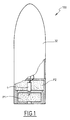
- FIG. 1 is a partial sectional view of a projectile 100 equipped with an ignition safety device 1 according to the invention.
- the projectile 100 has two propulsive charges P1 and P2 that one wish to initiate with some delay between them.
- the ignition safety device 1 is arranged in such a way as to trigger the firing of the two propellant charges of successively.
- Non-powered source represented which may be a battery incorporated in the projectile or integral with a launch tube (not shown) and connected to the projectile by broken wires during firing.
- FIG. 2a is a longitudinal sectional view of the ignition safety device 1 according to the invention in its security position.
- the ignition safety device 1 consists of a casing 4 of tubular form substantially cylindrical enclosing an electronic module 2 and a mechanical-pyrotechnic module 3 arranged in the case present in the extension of one another. In a variant, these modules could be arranged side by side.
- the module 2 is connected at one end to a connector 6, itself connected to a source of energy (not shown on this figure).
- the electronic module 2 consists of conventional electronic elements, such as accumulators of energy, an electronic timer, as well that speed and / or acceleration sensors to know the projectile ejection parameters and that it is not necessary to describe for the understanding of the invention.
- this one could be embedded in a coating 9, for example of the type silicone elastomer.
- the mechano-pyrotechnic module 3 has at one end an igniter support 30 extended by a body 15 to inside which slides an inner sheath 16.
- Body and sheath may be made of metallic material or synthetic material sufficiently resistant to stress mechanical.
- the mechano-pyrotechnic module 3 comprises at its another end a tubular outlet 5 cooperating with the P1 thruster
- FIG. 2b is a longitudinal sectional view of the support 30 and of the body 15 alone
- FIG. 2c is a sectional view longitudinal axis of the sheath 16 alone
- the body 15 abuts against one end of the tubular casing 4 which carries the tubular outlet 5. It has an internal bore 15b whose bottom constitutes a abutment surface 15a whose role will be explained below.
- the body 15 has at its side wall two channels longitudinal cylinders 21 and 22 (the latter represented in dotted lines) intended to contain respectively the chains pyrotechnics 11 and 12.
- the channel 21 encloses a chain slow pyrotechnic 11 and the channel 22 is empty.
- the side wall of the body 15 is pierced with an opening radial 19 which is arranged opposite the thruster P2 (no represent).
- the channel 22 communicates with a chamber 45 connected to the tubular outlet 5 carrying a relay 13.
- the channel 21 also communicates with the internal bore 15b by a radial opening 40 whose role will be explained below.
- the inner sheath 16 is slidably mounted on the inside of the body 15 and it is provided with two radial openings 24 and 35 axially offset from each other and with respect to the opening 19 of the body 15.
- This sheath 16 is under the shape of a simple sheath. It contains a piston 17 slidably mounted against the action of a spring 20.
- This piston comprises a solid portion 41 extended by a skirt 42. solid part 41 is in abutment against the abutment surface 15a of the body 15 and the skirt 42 partially surrounds the spring 20 which bears against the igniter support 30.
- the massive part 41 carries a peripheral collar 46 shear which axially immobilizes the sheath 16 relative to the piston 17 and to the body 15 in the safety position of Figure 2a.
- the solid portion 41 of the piston 17 is provided with a hole radial 43 for housing a finger 18 subjected to the action of a 23.
- the finger assembly 18 and spring 23 constitutes a system for securing the piston 17 and the sheath 16 in a configuration which will be explained below.
- the skirt 42 is provided with a radial bore 44.
- the support 30 carries a igniter 10 which is electrically connected to the module electronics 2 and which is next to the two chains pyrotechnic 11 and 12 housed in the respective channels 21 and 22.
- a first pyrotechnic relay 13 is disposed in the tubular outlet 5. It receives directly the gases produced by the igniter 10 which are led through the channel 22 and the chamber 45. It ensures the ignition of the thruster P1.
- a second pyrotechnic relay 14 is disposed in a housing 25 of the skirt 42 of the piston 17, in the vicinity of the bore 44.
- the device 1 is in the position of security.
- the sheath 16 closes the openings 19 and 40 of the body 15.
- the sheath 16 thus isolates the relay 14 of both the slow pyrotechnic chain 11 and the P2 thruster.
- Figure 2e is a cross-sectional view of the body 15 only, cut according to plan AA. This view in cutting allows to observe the layout of the channels cylindrical 21 and 22 placed side by side in the body 15, without communicating with each other, channel 21 enclosing the pyrotechnic chain 11 the channel 22 being empty.
- FIGS 3a to 3d illustrate the different phases of operation of the device according to the invention.
- the electronic module 2 commands the initiation of the igniter 10 ( Figure 3a).
- the gases of the latter penetrate both channels 21 and 22 simultaneously. ensure the initiation of the slow pyrotechnic chain 11 while directly lighting the first relay 13 through empty channel 22 and chamber 45.
- the ignition of the first relay 13 causes the initiation of the thruster P1.
- This translation of the sheath 16 positions the hole 44 of the piston as well as the opening 35 of the sheath 16 opposite of the opening 40 of the body 15.
- the end of the slow combustion pyrotechnic chain 11 is therefore connected to the second pyrotechnic relay 14.
- the chain 11 with slow combustion by through the opening 35 of the sheath 16 and the piercing 44 of the piston 17, initiates, at the end of its combustion, the second relay 14 disposed in the housing 25, then the thruster P2 via the opening 19 of the body 15. It has thus been realized in a simple manner a device allowing from a single igniter to ensure a successive and delayed initiation of two propellers P1 and P2.
- the operation of the device according to the invention is of course identical when the charges to be initiated are time-triggered pyrotechnic compositions, for example smoke compositions.
- the thruster P1 is not initiated, for example as following a fault of the first relay 13, the piston 17 and the sheath 16 do not move and the second relay 14 can not be initiated by the slow pyrotechnic chain.
- the device according to the invention thus ensures ignition safety of the second propellant. The latter can only be switched on after the delay whose duration is determined by the composition pyrotechnic delay 11 and only if the first thruster worked and completed its combustion.
- Relays 13 and 14 are pyrotechnic relays. They will be made and arranged so as to create a clearance sufficient gas and whose temperature will be sufficient high to ignite the pyrotechnic compositions of thrusters P1 and P2.
- non-return valve in the channel 22 of the chain 12 to combustion to prevent the gases from the combustion of P1 thruster does not come across this channel 22 disrupt the operation of the chain 11 slow combustion.
- Such an anti-return valve is conventional. He will be able to have a ball applied to a cone bearing by a return spring and closing a passage hole gas. The gases can then circulate only in one direction in channel 22.
- sealing elements such as O-rings arranged between the pieces concentric (body 15 / envelope 4, sheath 16 / body 15; piston 17 / sheath 16).
- the invention has been described here with the association of a slow pyrotechnic chain, including a delay pyrotechnics housed in a canal, and a fast chain in which channel 22 is free of any composition.
- each channel 21 and 22 contains a late pyrotechnic composition.
- the burning speeds and / or the lengths of each chain pyrotechnic 11, 12 will be chosen different depending needs.
- a device comprising more than two late-fire pyrotechnic chains.
- we will provide another relay, arranged in a room distinct from the piston, and which will communicate when the device will be in its armed position, on the one hand with the third pyrotechnic chain and secondly with a third composition or propellant charge to initiate.
Landscapes
- Engineering & Computer Science (AREA)
- General Engineering & Computer Science (AREA)
- Air Bags (AREA)
- Pharmaceuticals Containing Other Organic And Inorganic Compounds (AREA)
Abstract
Description
- la figure 1 représente en coupe un projectile équipé d'un dispositif de sécurité d'allumage selon l'invention,
- le figure 2a représente en coupe longitudinale le dispositif de sécurité d'allumage selon l'invention,
- les figures 2b à 2e sont des vues en coupe des pièces constituant le module mécano-pyrotechnique, et
- les figures 3a à 3d illustrent le dispositif de sécurité d'allumage selon l'invention à différentes étapes de fonctionnement.
Claims (10)
- Dispositif de sécurité d'allumage (1) d'au moins deux compositions pyrotechniques ou charges propulsives d'un projectile (100), caractérisé en ce qu'il comprend au moins deux chaínes pyrotechniques (11, 12) distinctes intégrées dans un dispositif mécanique (15, 16, 17) et initiées par un inflammateur unique (10), chaque chaíne pyrotechnique permettant par l'intermédiaire d'au moins un relais (13, 14) d'initier la composition pyrotechnique ou charge propulsive (P1, P2) correspondante, au moins une première chaíne pyrotechnique (11) étant à combustion plus lente qu' une deuxième chaíne pyrotechnique (12) à combustion ou action rapide.
- Dispositif de sécurité d'allumage (1) selon la revendication 1, caractérisé en ce que le dispositif mécanique (15, 16, 17) est constitué d'éléments mobiles les uns par rapport aux autres, permettant d'assurer une interruption de la ou des chaínes pyrotechniques lentes si la chaíne à combustion ou action rapide n'a pas fonctionné correctement.
- Dispositif de sécurité d'allumage (1) selon la revendication 2, caractérisé en ce que le dispositif mécanique est constitué d'un piston (17) coulissant dans une gaine interne (16) elle-même montée glissante dans un alésage (15b) d'un corps (15), la gaine portant au moins une ouverture (35) permettant, lorsque la gaine (16) se trouve dans une position armée de relier la ou les chaínes pyrotechniques lentes à au moins un des relais (14).
- Dispositif de sécurité d'allumage (1) selon la revendication 3, caractérisé en ce que le piston (17) est mobile sous l'action des gaz de combustion d'une composition pyrotechnique ou d'une charge propulsive initiée par la chaíne pyrotechnique rapide, contre l'action d'un ressort (20) en appui sur un support (30) solidaire du corps (15).
- Dispositif de sécurité d'allumage (1) selon la revendication 4, caractérisé en ce que le piston (17) est constitué d'une partie massive (41) prolongée par une jupe (42) munie d'un perçage radial (44) et renfermant le relais pyrotechnique (14).
- Dispositif de sécurité d'allumage (1) selon une des revendications 4 ou 5, caractérisé en ce qu'il comporte des moyens assurant le verrouillage du piston (17) et de la gaine (16) après déplacement du piston (17) sous l'action des gaz de combustion de la composition ou charge propulsive initiée par la chaíne pyrotechnique rapide (12).
- Dispositif de sécurité d'allumage (1) selon la revendication 6, caractérisé en ce que les moyens assurant le verrouillage du piston (17) et de la gaine (16) sont constitués par un doigt (18) disposé dans un trou radial (43) du piston (17) et soumis à l'action d'un ressort (23), doigt destiné à coopérer avec une première ouverture (24) portée par la gaine (16)
- Dispositif de sécurité d'allumage (1) selon une des revendications 5 à 7, caractérisé en ce que le corps (15) comprend deux canaux longitudinaux (21, 22), un au moins des canaux renfermant une composition pyrotechnique retard (11), une ouverture radiale (40) du corps (15) faisant communiquer le canal (21) renfermant la chaíne pyrotechnique lente (11) avec le perçage radial (44) de la jupe (42) du piston (17).
- Dispositif de sécurité d'allumage (1) selon la revendication 8, caractérisé en ce qu'un des canaux (12) du corps (15) est vide et permet de relier directement l'inflammateur (10) à un des relais (14).
- Dispositif de sécurité d'allumage (1) selon la revendication 8, caractérisé en ce que le corps (15) présente une ouverture radiale (19) disposée au niveau de la composition pyrotechnique ou charge propulsive P2, ouverture obturée par la gaine (16) quand elle est en position de sécurité.
Applications Claiming Priority (2)
| Application Number | Priority Date | Filing Date | Title |
|---|---|---|---|
| FR0312996 | 2003-11-05 | ||
| FR0312996A FR2861842B1 (fr) | 2003-11-05 | 2003-11-05 | Module mecano-pyrotechnique |
Publications (2)
| Publication Number | Publication Date |
|---|---|
| EP1530020A1 true EP1530020A1 (fr) | 2005-05-11 |
| EP1530020B1 EP1530020B1 (fr) | 2006-12-06 |
Family
ID=34429928
Family Applications (1)
| Application Number | Title | Priority Date | Filing Date |
|---|---|---|---|
| EP04292290A Expired - Lifetime EP1530020B1 (fr) | 2003-11-05 | 2004-09-23 | Dispositif d'allumage d'au moins deux compositions pyrotechniques ou charges propulsives d'un projectile |
Country Status (4)
| Country | Link |
|---|---|
| EP (1) | EP1530020B1 (fr) |
| AT (1) | ATE347680T1 (fr) |
| DE (1) | DE602004003544T2 (fr) |
| FR (1) | FR2861842B1 (fr) |
Cited By (2)
| Publication number | Priority date | Publication date | Assignee | Title |
|---|---|---|---|---|
| WO2014012815A1 (fr) * | 2012-07-18 | 2014-01-23 | Rheinmetall Waffe Munition Gmbh, Patente | Élément retardateur commandé par pression, et munition associée |
| FR3010784A1 (fr) * | 2013-09-16 | 2015-03-20 | Nexter Munitions | Detonateur a retard |
Families Citing this family (1)
| Publication number | Priority date | Publication date | Assignee | Title |
|---|---|---|---|---|
| DE102013013705A1 (de) | 2013-08-20 | 2015-02-26 | Rheinmetall Waffe Munition Gmbh | Pyrotechnische Verzögerungseinrichtung für elnen Munitionszünder und Mörsergranate mit einer derartigen Verzögerungseinrichtung |
Citations (5)
| Publication number | Priority date | Publication date | Assignee | Title |
|---|---|---|---|---|
| DE325292C (de) * | 1918-06-11 | 1920-09-23 | Siemens Schuckertwerke G M B H | Doppelzuender fuer Granaten |
| GB736122A (en) * | 1952-03-18 | 1955-08-31 | Henri Georges Bouly | Improvements in percussion fuzes |
| FR2149000A5 (en) * | 1971-08-12 | 1973-03-23 | Ruggieri Ets | Electropyrotechnic igniter - for munitions such as illuminating flare bomb etc |
| US4006689A (en) * | 1974-08-01 | 1977-02-08 | Etat Francais | Pyrotechnical safety relay |
| GB1545133A (en) * | 1976-03-29 | 1979-05-02 | Luchaire Sa | Safety-type delay-action starting systems for missiles notably self-propelled missiles |
-
2003
- 2003-11-05 FR FR0312996A patent/FR2861842B1/fr not_active Expired - Fee Related
-
2004
- 2004-09-23 DE DE602004003544T patent/DE602004003544T2/de not_active Expired - Fee Related
- 2004-09-23 AT AT04292290T patent/ATE347680T1/de not_active IP Right Cessation
- 2004-09-23 EP EP04292290A patent/EP1530020B1/fr not_active Expired - Lifetime
Patent Citations (5)
| Publication number | Priority date | Publication date | Assignee | Title |
|---|---|---|---|---|
| DE325292C (de) * | 1918-06-11 | 1920-09-23 | Siemens Schuckertwerke G M B H | Doppelzuender fuer Granaten |
| GB736122A (en) * | 1952-03-18 | 1955-08-31 | Henri Georges Bouly | Improvements in percussion fuzes |
| FR2149000A5 (en) * | 1971-08-12 | 1973-03-23 | Ruggieri Ets | Electropyrotechnic igniter - for munitions such as illuminating flare bomb etc |
| US4006689A (en) * | 1974-08-01 | 1977-02-08 | Etat Francais | Pyrotechnical safety relay |
| GB1545133A (en) * | 1976-03-29 | 1979-05-02 | Luchaire Sa | Safety-type delay-action starting systems for missiles notably self-propelled missiles |
Cited By (2)
| Publication number | Priority date | Publication date | Assignee | Title |
|---|---|---|---|---|
| WO2014012815A1 (fr) * | 2012-07-18 | 2014-01-23 | Rheinmetall Waffe Munition Gmbh, Patente | Élément retardateur commandé par pression, et munition associée |
| FR3010784A1 (fr) * | 2013-09-16 | 2015-03-20 | Nexter Munitions | Detonateur a retard |
Also Published As
| Publication number | Publication date |
|---|---|
| ATE347680T1 (de) | 2006-12-15 |
| FR2861842A1 (fr) | 2005-05-06 |
| FR2861842B1 (fr) | 2007-12-21 |
| DE602004003544D1 (de) | 2007-01-18 |
| DE602004003544T2 (de) | 2007-07-05 |
| EP1530020B1 (fr) | 2006-12-06 |
Similar Documents
| Publication | Publication Date | Title |
|---|---|---|
| EP0048204B1 (fr) | Cartouche à actionnement pyrotechnique de charge utile avec sécurité | |
| FR2763548A1 (fr) | Generateur pyrotechnique de gaz adaptatif a chambres tubulaires pour coussin de protection | |
| FR2788846A1 (fr) | Generateur de gaz hybride muni d'un initiateur a chargement explosif profile | |
| EP0389358A1 (fr) | Système d'ouverture d'un empennage déployant pour projectile | |
| EP1138923B1 (fr) | Moteur autopropulsé à plusieurs étages et système de séparation situé entre deux étages consécutifs | |
| CH628422A5 (fr) | Subprojectile destine a etre expulse d'un projectile. | |
| EP0901946B1 (fr) | Générateur pyrotechnique adaptatif de gaz pour coussin de protection avec dispositif de neutralisation | |
| FR2806789A1 (fr) | Tube allumeur pour une munition d'artillerie | |
| WO2014132004A1 (fr) | Munition a puissance explosive modulable | |
| EP0545764B1 (fr) | Dispositif de verrouillage d'une enveloppe contenant des matières pyrotechniques | |
| EP1530020B1 (fr) | Dispositif d'allumage d'au moins deux compositions pyrotechniques ou charges propulsives d'un projectile | |
| EP2827091B1 (fr) | Initiateur électrique ayant deux modes de fonctionnement | |
| EP0404644B1 (fr) | Dispositif électropyrotechnique destiné à déclencher le fonctionnement d'un générateur de gaz | |
| FR3005724A1 (fr) | Generateur de gaz pyrotechnique | |
| EP1034411B1 (fr) | Generateur pyroacoustique pour la protection de sous-marins et de batiments de surface | |
| EP2029956B1 (fr) | Allumeur de securite pour dispositif pyrotechnique | |
| FR2932561A1 (fr) | Micro initiateur securise | |
| EP3163249B1 (fr) | Allumeur pour propulseur | |
| FR2555733A1 (fr) | Fusee percutante pour projectiles | |
| EP2554529B1 (fr) | Détonateur de sécurité | |
| EP1577635B1 (fr) | Dispositif d'initiation de deux charges explosives et tête militaire mettant en oeuvre un tel dispositif d'initiation | |
| FR2678054A1 (fr) | Procede pour accelerer un projectile, et tube accelerateur a effet dynamique pour sa mise en óoeuvre. | |
| EP4641128A1 (fr) | Cartouche pour dispositif incapacitant a impulsions electriques | |
| EP0678725A1 (fr) | Dispositif d'allumage d'une charge propulsive | |
| FR2907732A1 (fr) | Generateur de gaz hybride de gonflage d'un coussin de securite pour vehicule automobile |
Legal Events
| Date | Code | Title | Description |
|---|---|---|---|
| PUAI | Public reference made under article 153(3) epc to a published international application that has entered the european phase |
Free format text: ORIGINAL CODE: 0009012 |
|
| AK | Designated contracting states |
Kind code of ref document: A1 Designated state(s): AT BE BG CH CY CZ DE DK EE ES FI FR GB GR HU IE IT LI LU MC NL PL PT RO SE SI SK TR |
|
| AX | Request for extension of the european patent |
Extension state: AL HR LT LV MK |
|
| 17P | Request for examination filed |
Effective date: 20051102 |
|
| AKX | Designation fees paid |
Designated state(s): AT BE BG CH CY CZ DE DK EE ES FI FR GB GR HU IE IT LI LU MC NL PL PT RO SE SI SK TR |
|
| GRAP | Despatch of communication of intention to grant a patent |
Free format text: ORIGINAL CODE: EPIDOSNIGR1 |
|
| GRAS | Grant fee paid |
Free format text: ORIGINAL CODE: EPIDOSNIGR3 |
|
| GRAA | (expected) grant |
Free format text: ORIGINAL CODE: 0009210 |
|
| AK | Designated contracting states |
Kind code of ref document: B1 Designated state(s): AT BE BG CH CY CZ DE DK EE ES FI FR GB GR HU IE IT LI LU MC NL PL PT RO SE SI SK TR |
|
| PG25 | Lapsed in a contracting state [announced via postgrant information from national office to epo] |
Ref country code: IT Free format text: LAPSE BECAUSE OF FAILURE TO SUBMIT A TRANSLATION OF THE DESCRIPTION OR TO PAY THE FEE WITHIN THE PRESCRIBED TIME-LIMIT;WARNING: LAPSES OF ITALIAN PATENTS WITH EFFECTIVE DATE BEFORE 2007 MAY HAVE OCCURRED AT ANY TIME BEFORE 2007. THE CORRECT EFFECTIVE DATE MAY BE DIFFERENT FROM THE ONE RECORDED. Effective date: 20061206 Ref country code: NL Free format text: LAPSE BECAUSE OF FAILURE TO SUBMIT A TRANSLATION OF THE DESCRIPTION OR TO PAY THE FEE WITHIN THE PRESCRIBED TIME-LIMIT Effective date: 20061206 Ref country code: SI Free format text: LAPSE BECAUSE OF FAILURE TO SUBMIT A TRANSLATION OF THE DESCRIPTION OR TO PAY THE FEE WITHIN THE PRESCRIBED TIME-LIMIT Effective date: 20061206 Ref country code: CZ Free format text: LAPSE BECAUSE OF FAILURE TO SUBMIT A TRANSLATION OF THE DESCRIPTION OR TO PAY THE FEE WITHIN THE PRESCRIBED TIME-LIMIT Effective date: 20061206 Ref country code: AT Free format text: LAPSE BECAUSE OF FAILURE TO SUBMIT A TRANSLATION OF THE DESCRIPTION OR TO PAY THE FEE WITHIN THE PRESCRIBED TIME-LIMIT Effective date: 20061206 Ref country code: PL Free format text: LAPSE BECAUSE OF FAILURE TO SUBMIT A TRANSLATION OF THE DESCRIPTION OR TO PAY THE FEE WITHIN THE PRESCRIBED TIME-LIMIT Effective date: 20061206 Ref country code: FI Free format text: LAPSE BECAUSE OF FAILURE TO SUBMIT A TRANSLATION OF THE DESCRIPTION OR TO PAY THE FEE WITHIN THE PRESCRIBED TIME-LIMIT Effective date: 20061206 Ref country code: SK Free format text: LAPSE BECAUSE OF FAILURE TO SUBMIT A TRANSLATION OF THE DESCRIPTION OR TO PAY THE FEE WITHIN THE PRESCRIBED TIME-LIMIT Effective date: 20061206 Ref country code: RO Free format text: LAPSE BECAUSE OF FAILURE TO SUBMIT A TRANSLATION OF THE DESCRIPTION OR TO PAY THE FEE WITHIN THE PRESCRIBED TIME-LIMIT Effective date: 20061206 Ref country code: IE Free format text: LAPSE BECAUSE OF FAILURE TO SUBMIT A TRANSLATION OF THE DESCRIPTION OR TO PAY THE FEE WITHIN THE PRESCRIBED TIME-LIMIT Effective date: 20061206 Ref country code: DK Free format text: LAPSE BECAUSE OF FAILURE TO SUBMIT A TRANSLATION OF THE DESCRIPTION OR TO PAY THE FEE WITHIN THE PRESCRIBED TIME-LIMIT Effective date: 20061206 |
|
| REG | Reference to a national code |
Ref country code: GB Ref legal event code: FG4D Free format text: NOT ENGLISH |
|
| REG | Reference to a national code |
Ref country code: CH Ref legal event code: EP |
|
| GBT | Gb: translation of ep patent filed (gb section 77(6)(a)/1977) |
Effective date: 20061208 |
|
| REG | Reference to a national code |
Ref country code: IE Ref legal event code: FG4D Free format text: LANGUAGE OF EP DOCUMENT: FRENCH |
|
| REF | Corresponds to: |
Ref document number: 602004003544 Country of ref document: DE Date of ref document: 20070118 Kind code of ref document: P |
|
| REG | Reference to a national code |
Ref country code: CH Ref legal event code: NV Representative=s name: ING. MARCO ZARDI C/O M. ZARDI & CO. S.A. |
|
| PG25 | Lapsed in a contracting state [announced via postgrant information from national office to epo] |
Ref country code: BG Free format text: LAPSE BECAUSE OF FAILURE TO SUBMIT A TRANSLATION OF THE DESCRIPTION OR TO PAY THE FEE WITHIN THE PRESCRIBED TIME-LIMIT Effective date: 20070306 |
|
| PG25 | Lapsed in a contracting state [announced via postgrant information from national office to epo] |
Ref country code: ES Free format text: LAPSE BECAUSE OF FAILURE TO SUBMIT A TRANSLATION OF THE DESCRIPTION OR TO PAY THE FEE WITHIN THE PRESCRIBED TIME-LIMIT Effective date: 20070317 |
|
| REG | Reference to a national code |
Ref country code: SE Ref legal event code: TRGR |
|
| PG25 | Lapsed in a contracting state [announced via postgrant information from national office to epo] |
Ref country code: PT Free format text: LAPSE BECAUSE OF FAILURE TO SUBMIT A TRANSLATION OF THE DESCRIPTION OR TO PAY THE FEE WITHIN THE PRESCRIBED TIME-LIMIT Effective date: 20070507 |
|
| NLV1 | Nl: lapsed or annulled due to failure to fulfill the requirements of art. 29p and 29m of the patents act | ||
| PLBE | No opposition filed within time limit |
Free format text: ORIGINAL CODE: 0009261 |
|
| STAA | Information on the status of an ep patent application or granted ep patent |
Free format text: STATUS: NO OPPOSITION FILED WITHIN TIME LIMIT |
|
| 26N | No opposition filed |
Effective date: 20070907 |
|
| BERE | Be: lapsed |
Owner name: GIAT INDUSTRIES Effective date: 20070930 |
|
| PG25 | Lapsed in a contracting state [announced via postgrant information from national office to epo] |
Ref country code: GR Free format text: LAPSE BECAUSE OF FAILURE TO SUBMIT A TRANSLATION OF THE DESCRIPTION OR TO PAY THE FEE WITHIN THE PRESCRIBED TIME-LIMIT Effective date: 20070307 Ref country code: SE Free format text: LAPSE BECAUSE OF NON-PAYMENT OF DUE FEES Effective date: 20070924 Ref country code: MC Free format text: LAPSE BECAUSE OF NON-PAYMENT OF DUE FEES Effective date: 20070930 |
|
| EUG | Se: european patent has lapsed | ||
| PG25 | Lapsed in a contracting state [announced via postgrant information from national office to epo] |
Ref country code: DE Free format text: LAPSE BECAUSE OF NON-PAYMENT OF DUE FEES Effective date: 20080401 |
|
| PG25 | Lapsed in a contracting state [announced via postgrant information from national office to epo] |
Ref country code: BE Free format text: LAPSE BECAUSE OF NON-PAYMENT OF DUE FEES Effective date: 20070930 |
|
| PG25 | Lapsed in a contracting state [announced via postgrant information from national office to epo] |
Ref country code: EE Free format text: LAPSE BECAUSE OF FAILURE TO SUBMIT A TRANSLATION OF THE DESCRIPTION OR TO PAY THE FEE WITHIN THE PRESCRIBED TIME-LIMIT Effective date: 20061206 |
|
| REG | Reference to a national code |
Ref country code: CH Ref legal event code: PL |
|
| GBPC | Gb: european patent ceased through non-payment of renewal fee |
Effective date: 20080923 |
|
| PG25 | Lapsed in a contracting state [announced via postgrant information from national office to epo] |
Ref country code: CH Free format text: LAPSE BECAUSE OF NON-PAYMENT OF DUE FEES Effective date: 20070930 Ref country code: LI Free format text: LAPSE BECAUSE OF NON-PAYMENT OF DUE FEES Effective date: 20070930 |
|
| PG25 | Lapsed in a contracting state [announced via postgrant information from national office to epo] |
Ref country code: LU Free format text: LAPSE BECAUSE OF NON-PAYMENT OF DUE FEES Effective date: 20070923 Ref country code: CY Free format text: LAPSE BECAUSE OF FAILURE TO SUBMIT A TRANSLATION OF THE DESCRIPTION OR TO PAY THE FEE WITHIN THE PRESCRIBED TIME-LIMIT Effective date: 20061206 |
|
| PG25 | Lapsed in a contracting state [announced via postgrant information from national office to epo] |
Ref country code: HU Free format text: LAPSE BECAUSE OF FAILURE TO SUBMIT A TRANSLATION OF THE DESCRIPTION OR TO PAY THE FEE WITHIN THE PRESCRIBED TIME-LIMIT Effective date: 20070607 Ref country code: TR Free format text: LAPSE BECAUSE OF FAILURE TO SUBMIT A TRANSLATION OF THE DESCRIPTION OR TO PAY THE FEE WITHIN THE PRESCRIBED TIME-LIMIT Effective date: 20061206 |
|
| PG25 | Lapsed in a contracting state [announced via postgrant information from national office to epo] |
Ref country code: CH Free format text: LAPSE BECAUSE OF NON-PAYMENT OF DUE FEES Effective date: 20080930 Ref country code: LI Free format text: LAPSE BECAUSE OF NON-PAYMENT OF DUE FEES Effective date: 20080930 |
|
| PG25 | Lapsed in a contracting state [announced via postgrant information from national office to epo] |
Ref country code: GB Free format text: LAPSE BECAUSE OF NON-PAYMENT OF DUE FEES Effective date: 20080923 |
|
| REG | Reference to a national code |
Ref country code: FR Ref legal event code: PLFP Year of fee payment: 12 |
|
| REG | Reference to a national code |
Ref country code: FR Ref legal event code: PLFP Year of fee payment: 13 |
|
| PGFP | Annual fee paid to national office [announced via postgrant information from national office to epo] |
Ref country code: FR Payment date: 20160822 Year of fee payment: 13 |
|
| REG | Reference to a national code |
Ref country code: FR Ref legal event code: ST Effective date: 20180531 |
|
| PG25 | Lapsed in a contracting state [announced via postgrant information from national office to epo] |
Ref country code: FR Free format text: LAPSE BECAUSE OF NON-PAYMENT OF DUE FEES Effective date: 20171002 |