EP1529993A1 - Metallic bellows, manufacturing method therefor, and accumulator therewith - Google Patents
Metallic bellows, manufacturing method therefor, and accumulator therewith Download PDFInfo
- Publication number
- EP1529993A1 EP1529993A1 EP04026284A EP04026284A EP1529993A1 EP 1529993 A1 EP1529993 A1 EP 1529993A1 EP 04026284 A EP04026284 A EP 04026284A EP 04026284 A EP04026284 A EP 04026284A EP 1529993 A1 EP1529993 A1 EP 1529993A1
- Authority
- EP
- European Patent Office
- Prior art keywords
- bellows
- metallic
- metallic bellows
- surface working
- stainless steel
- Prior art date
- Legal status (The legal status is an assumption and is not a legal conclusion. Google has not performed a legal analysis and makes no representation as to the accuracy of the status listed.)
- Granted
Links
Images

Classifications
-
- C—CHEMISTRY; METALLURGY
- C21—METALLURGY OF IRON
- C21D—MODIFYING THE PHYSICAL STRUCTURE OF FERROUS METALS; GENERAL DEVICES FOR HEAT TREATMENT OF FERROUS OR NON-FERROUS METALS OR ALLOYS; MAKING METAL MALLEABLE, e.g. BY DECARBURISATION OR TEMPERING
- C21D8/00—Modifying the physical properties of ferrous metals or ferrous alloys by deformation combined with, or followed by, heat treatment
- C21D8/10—Modifying the physical properties of ferrous metals or ferrous alloys by deformation combined with, or followed by, heat treatment during manufacturing of tubular bodies
-
- C—CHEMISTRY; METALLURGY
- C21—METALLURGY OF IRON
- C21D—MODIFYING THE PHYSICAL STRUCTURE OF FERROUS METALS; GENERAL DEVICES FOR HEAT TREATMENT OF FERROUS OR NON-FERROUS METALS OR ALLOYS; MAKING METAL MALLEABLE, e.g. BY DECARBURISATION OR TEMPERING
- C21D7/00—Modifying the physical properties of iron or steel by deformation
- C21D7/02—Modifying the physical properties of iron or steel by deformation by cold working
- C21D7/04—Modifying the physical properties of iron or steel by deformation by cold working of the surface
- C21D7/06—Modifying the physical properties of iron or steel by deformation by cold working of the surface by shot-peening or the like
-
- F—MECHANICAL ENGINEERING; LIGHTING; HEATING; WEAPONS; BLASTING
- F15—FLUID-PRESSURE ACTUATORS; HYDRAULICS OR PNEUMATICS IN GENERAL
- F15B—SYSTEMS ACTING BY MEANS OF FLUIDS IN GENERAL; FLUID-PRESSURE ACTUATORS, e.g. SERVOMOTORS; DETAILS OF FLUID-PRESSURE SYSTEMS, NOT OTHERWISE PROVIDED FOR
- F15B1/00—Installations or systems with accumulators; Supply reservoir or sump assemblies
- F15B1/02—Installations or systems with accumulators
- F15B1/04—Accumulators
- F15B1/08—Accumulators using a gas cushion; Gas charging devices; Indicators or floats therefor
- F15B1/10—Accumulators using a gas cushion; Gas charging devices; Indicators or floats therefor with flexible separating means
- F15B1/103—Accumulators using a gas cushion; Gas charging devices; Indicators or floats therefor with flexible separating means the separating means being bellows
-
- F—MECHANICAL ENGINEERING; LIGHTING; HEATING; WEAPONS; BLASTING
- F16—ENGINEERING ELEMENTS AND UNITS; GENERAL MEASURES FOR PRODUCING AND MAINTAINING EFFECTIVE FUNCTIONING OF MACHINES OR INSTALLATIONS; THERMAL INSULATION IN GENERAL
- F16J—PISTONS; CYLINDERS; SEALINGS
- F16J3/00—Diaphragms; Bellows; Bellows pistons
- F16J3/04—Bellows
- F16J3/047—Metallic bellows
-
- C—CHEMISTRY; METALLURGY
- C21—METALLURGY OF IRON
- C21D—MODIFYING THE PHYSICAL STRUCTURE OF FERROUS METALS; GENERAL DEVICES FOR HEAT TREATMENT OF FERROUS OR NON-FERROUS METALS OR ALLOYS; MAKING METAL MALLEABLE, e.g. BY DECARBURISATION OR TEMPERING
- C21D6/00—Heat treatment of ferrous alloys
- C21D6/002—Heat treatment of ferrous alloys containing Cr
-
- C—CHEMISTRY; METALLURGY
- C21—METALLURGY OF IRON
- C21D—MODIFYING THE PHYSICAL STRUCTURE OF FERROUS METALS; GENERAL DEVICES FOR HEAT TREATMENT OF FERROUS OR NON-FERROUS METALS OR ALLOYS; MAKING METAL MALLEABLE, e.g. BY DECARBURISATION OR TEMPERING
- C21D6/00—Heat treatment of ferrous alloys
- C21D6/02—Hardening by precipitation
-
- F—MECHANICAL ENGINEERING; LIGHTING; HEATING; WEAPONS; BLASTING
- F15—FLUID-PRESSURE ACTUATORS; HYDRAULICS OR PNEUMATICS IN GENERAL
- F15B—SYSTEMS ACTING BY MEANS OF FLUIDS IN GENERAL; FLUID-PRESSURE ACTUATORS, e.g. SERVOMOTORS; DETAILS OF FLUID-PRESSURE SYSTEMS, NOT OTHERWISE PROVIDED FOR
- F15B2201/00—Accumulators
- F15B2201/20—Accumulator cushioning means
- F15B2201/205—Accumulator cushioning means using gas
-
- F—MECHANICAL ENGINEERING; LIGHTING; HEATING; WEAPONS; BLASTING
- F15—FLUID-PRESSURE ACTUATORS; HYDRAULICS OR PNEUMATICS IN GENERAL
- F15B—SYSTEMS ACTING BY MEANS OF FLUIDS IN GENERAL; FLUID-PRESSURE ACTUATORS, e.g. SERVOMOTORS; DETAILS OF FLUID-PRESSURE SYSTEMS, NOT OTHERWISE PROVIDED FOR
- F15B2201/00—Accumulators
- F15B2201/30—Accumulator separating means
- F15B2201/315—Accumulator separating means having flexible separating means
- F15B2201/3153—Accumulator separating means having flexible separating means the flexible separating means being bellows
-
- F—MECHANICAL ENGINEERING; LIGHTING; HEATING; WEAPONS; BLASTING
- F15—FLUID-PRESSURE ACTUATORS; HYDRAULICS OR PNEUMATICS IN GENERAL
- F15B—SYSTEMS ACTING BY MEANS OF FLUIDS IN GENERAL; FLUID-PRESSURE ACTUATORS, e.g. SERVOMOTORS; DETAILS OF FLUID-PRESSURE SYSTEMS, NOT OTHERWISE PROVIDED FOR
- F15B2201/00—Accumulators
- F15B2201/40—Constructional details of accumulators not otherwise provided for
- F15B2201/41—Liquid ports
- F15B2201/413—Liquid ports having multiple liquid ports
-
- F—MECHANICAL ENGINEERING; LIGHTING; HEATING; WEAPONS; BLASTING
- F15—FLUID-PRESSURE ACTUATORS; HYDRAULICS OR PNEUMATICS IN GENERAL
- F15B—SYSTEMS ACTING BY MEANS OF FLUIDS IN GENERAL; FLUID-PRESSURE ACTUATORS, e.g. SERVOMOTORS; DETAILS OF FLUID-PRESSURE SYSTEMS, NOT OTHERWISE PROVIDED FOR
- F15B2201/00—Accumulators
- F15B2201/40—Constructional details of accumulators not otherwise provided for
- F15B2201/415—Gas ports
-
- F—MECHANICAL ENGINEERING; LIGHTING; HEATING; WEAPONS; BLASTING
- F15—FLUID-PRESSURE ACTUATORS; HYDRAULICS OR PNEUMATICS IN GENERAL
- F15B—SYSTEMS ACTING BY MEANS OF FLUIDS IN GENERAL; FLUID-PRESSURE ACTUATORS, e.g. SERVOMOTORS; DETAILS OF FLUID-PRESSURE SYSTEMS, NOT OTHERWISE PROVIDED FOR
- F15B2201/00—Accumulators
- F15B2201/60—Assembling or methods for making accumulators
- F15B2201/61—Assembling or methods for making separating means therefor
Definitions
- the present invention relates to a bellows which is used for, for example, vehicle suspension devices, gas springs, accumulators, and vacuum apparatuses, and relates to a manufacturing method for the bellows.
- JIS Japanese Industrial Standard
- SUSS04 precipitation hardening stainless steel
- first, both longitudinal sides of a stainless steel plate having an appropriate thickness are brought into contact with each other and are connected by arc welding, so that a material pipe is produced.
- the material pipe is cut at a predetermined length and is then subjected to cold rolling using, for example, spinning working so as to have a predetermined thickness of a bellows.
- the pipe is subjected to solution heat treatment by heating to a solution temperature thereof, and is then subjected to plastic working such as hydraulic bulging so as to be formed into a bellows.
- solution heat treatment by heating to a solution temperature thereof, and is then subjected to plastic working such as hydraulic bulging so as to be formed into a bellows.
- plastic working such as hydraulic bulging so as to be formed into a bellows.
- precipitation hardening heat treatment is further performed.
- a metallic bellows is dynamically used so as to act as, for example, a spring
- setting is performed so as to stabilize the loading property of the bellows after precipitation hardening heat treatment, and surface working is then performed by providing compressive residual stress to a surface of the bellows so as to improve durability thereof.
- the surface working is performed by shot peening in which metallic particles are shot at a surface of the bellows at high speed or by honing in which glass beads are used instead of the metallic particles (for example, paragraphs 0015 to 0022, Table 1, and Fig. 1 in Japanese Unexamined Patent Application Publication No. 2001-304412).
- Austenite stainless steel such as SUS304 is better in view of workability (for example, paragraphs 0006 to 0013, and Figs. 1, 3, 4 and 6 in Japanese Unexamined Patent Application Publication No. 2003-172449).
- a metallic bellows made of SUS304 is low in material strength, whereby the design maximum stress thereof is 850 MPa.
- high strength materials may be used.
- An example of the high strength material is SUS631 of precipitation hardening semi-austenite stainless steel.
- the fatigue strength of the bellows made of SUS631 is lower than that of SUS304 as shown in Fig. 8.
- the material strength is increased, the workability is reduced due to decreased elongation of the material.
- the fatigue strength may be reduced due to material defects such as micro-cracks generated in the bulging.
- an object of the present invention is to provide a metallic bellows which is composed of a material having high material strength and having high fatigue strength by preventing generation of material defects such as micro-cracks.
- the inventor has been intensively researching metallic bellows so that the fatigue strength of the metallic bellows may be improved by appropriate working on precipitation hardening stainless steel.
- the inventor found that average grain size, hardness between a ridge portion and a valley portion of a bellows, and compressive residual stress of surfaces of ridge portions and valley portions of a bellows have respectively an appropriate range for a metallic bellows, and the inventor thereby made the present invention.
- a metallic bellows of the present invention may be made based on the above findings.
- the metallic bellows composed of precipitation hardening stainless steel, comprising: ridge portions and valley portions formed alternately and continuously; an average grain size of 10 to 15 ⁇ m; and compressive residual stress of not less than 500 MPa provided to at least surfaces of the ridge portions and the valleys by surface working.
- a method of manufacturing a metallic bellows of the present invention comprises steps of: cold rolling a pipe constructed such that both edges of a plate composed of precipitation hardening stainless steel are connected to each other by welding; fining an average grain size of the precipitation hardening stainless steel to 10 to 15 ⁇ m by annealing; forming the pipe into a bellows having an axial direction; precipitation age hardening heat treating the bellows; setting the bellows by tensile loading or compressive loading in the axial direction of the bellows, so that the bellows has a predetermined height with no load; and providing compressive residual stress of not less than 500 MPa to an inside face or an outside face of the bellows by surface working.
- yield stress is increased by fining the average grain size of the bellows to 10 to 15 ⁇ m, so that generation of slip bands can be inhibited.
- Length of cracks transmitted by about two grain sizes along slip bands can be decreased.
- Roughness of the surface of the bellows can be smoothed, and notch sensitivity thereof can thereby be relieved.
- the average grain size of the bellows is more than 15 ⁇ m, effect of grain refining cannot be obtained.
- the average grain size of the bellows is less than 10 ⁇ m, it is difficult to produce the bellows by controlling by annealing.
- the present invention since fatigue limit is improved by fining grains of the bellows, working stress of the bellows can be set high. As a result, the number of the ridge portions of the bellows can be reduced, so that the bellows and apparatuses in which the bellows is used can be miniaturized. Material cost and manufacturing cost can be reduced because of miniaturization thereof.
- FIG. 1 shows an accumulator 10 in which a metallic bellows 16 of the embodiment is provided.
- Oil generated in a pressure source (not shown in the figures) is introduced into the accumulator 10 via an inflow opening 11 and an introduction port 26.
- Gas 19 sealed in a gas chamber 18 and the bellows 16 are compressed by the oil introduced in the accumulator 10, so that pressure accumulation is performed in the accumulator 10.
- the oil is supplied to a hydraulic device (not shown in the figures) via an outflow opening 12 by the accumulated pressure of the gas so as to drive the hydraulic device.
- a pressure vessel 13 of the accumulator 10 has a metallic cylindrical-shaped shell 14, and a first end member 24 and a second end member 25 which are mounted to both end portions of the metallic cylindrical-shaped shell 14 by welding, etc.
- the metallic bellows 16 functions as a partition member 15 partitioning an interior of the pressure vessel 13 into a hydraulic chamber 17 and the gas chamber 18.
- the metallic bellows 16 is composed of precipitation hardening stainless steel.
- a fixing end portion 27 of the metallic bellows 16 is connected to the second end portion 25 in an air-tight state by welding.
- a bellows cap 21 is connected to the other end side of the bellows 16 in an air-tight state by welding or caulking. The bellows cap 21 can be elastically moved together with the metallic bellows 16 in an axial direction by pressure change of oil flowing from the inflow opening 11.
- an inert gas such as a nitrogen gas or a helium gas, or air which is used, depending on operation conditions, is sealed at a pressure higher than atmospheric pressure.
- the gas is injected from an injection opening 22 provided at the second end member 22.
- a predetermined amount of gas volume controlling liquid 20 is also injected into the gas chamber 18.
- the injection opening 22 is closed by a plug 23 having a male screw, etc.
- a corrugated bellows shown in Fig. 2 or a U-shaped bellows 31 shown in Fig. 3 is used as the bellows 16.
- corrugations 30 having valley portions 33 and ridge portions 32 are closely contacted with each other when the bellows is maximally compressed.
- the U-shaped bellows 31 has a U-shaped cross section of valley portions and ridge portions.
- a seal member 28 composed of an elastic body such as a rubber is provided on a face of a side of the hydraulic chamber 17 of the bellows cap 21. This seal member 28 functions as a seal mechanism 29 together with the first end member 24.
- Fig. 4 shows a manufacturing process for a metallic bellows.
- An example of a metallic bellows actually produced will be described below.
- a pipe of precipitation hardening stainless steel was subjected to cold rolling such as spinning working so as to have a predetermined wall thickness.
- SUS631 was used as the semi-austenite type.
- SUS633 (AM350) can be used as the semi-austenite type, and AISI1653 can be used as the austenite type.
- the precipitation hardening stainless steel having a thickness of 100 to 400 ⁇ m is used.
- grains thereof were fined by bright annealing (BA processing).
- the grains formed to be flat by cold rolling new crystals are generated from sub-grains thereof by heating by annealing, so that grains thereof are grown. As a result, recrystallization is completed.
- the grains are fined so as to have an average grain size of 10 to 15 ⁇ m by controlling reduction rate of cold rolling, and temperature and time of annealing.
- the yield stress is increased by fining the grains, so that generation of slip bands can be inhibited.
- the length of cracks transmitted by about one to two grain sizes along the slip bands can be decreased.
- the surface roughness is smoothed, so that the notch sensitivity is relieved.
- the reduction rate of cold rolling (cross section reduction rate) is favorably set at 3 to 40%
- the temperature of annealing is favorably set 900 to 950°C
- the annealing time is favorably set at 1 to 5 minutes.
- bright annealing was performed at a temperature of 950°C for 5 minutes.
- the reduction rate of cold rolling was set at 13%.
- a metallic bellows 16 formed in the shape of a cornice by bulging as shown in Fig. 2 or 3 was obtained.
- the pipe was compressed in an axial direction by pressing so as to be formed in a corrugated shape, so that the metallic bellows was produced as a corrugated bellows 30.
- the close contact of the corrugated bellows 30 can be more decreased than that of a U-shaped bellows 31, micro-cracks are easily generated in the corrugated bellows 30 since ridge portions 32 and valley portions 33 are greatly deformed.
- a bellows is formed by increasing a size of a pipe, deformation of ridge portions is greater than that of valley portions, so that hardness of the ridge portions is greater than that of the valley portions.
- a bellows is formed by reducing the size of a pipe, deformation of valley portions is greater than that of ridge portions, so that hardness of the valley portions is greater than that of the ridge portions.
- Fig. 5 shows a case of a bellows made of SUS631 of precipitation hardening semi-austenite stainless steel which was heated to a temperature of 480°C for an hour.
- Fig. 5 shows results obtained by measuring hardness of 18 points which are positioned from the outside to the inside of the bellows by a Micro Vickers hardness tester. It is confirmed that the bellows after precipitation age hardening heat treatment is harder than before the heat treatment.
- Fig. 5 is an example of a bellows formed by increasing the size of the pipe, the hardness of thickness direction center portion of the ridge portion is 450 to 600 Hv, and the hardness of thickness direction center portion of the valley portion is 250 to 450 Hv.
- the metallic bellows was subjected to setting by loading in an axial direction thereof so as to have a predetermined free height.
- a first step honing was performed by shooting glass beads at high speed so as to provide residual stress to the inside face and the outer face of the metallic bellows.
- the glass beads were about 0.1 mm
- an aspirator type honing machine of air injection type was used, and the air pressure was about 0.3 MPa.
- compressive residual stress of not less than 500 MPa was provided to the outer surfaces of the ridge portions.
- Honing was performed by using glass beads having a size of 38 ⁇ m so as to decrease the high compressive residual stress and the roughness of the metallic bellows surface generated in the first step honing, so that the compressive residual stress of the metallic bellows surface was not less than 600 MPa.
- the metallic bellows produced in the above manner had an average grain size of 10 to 15 ⁇ m.
- Table 1 shows measured results of the hardness, the compressive residual stress, the maximum surface roughness of austenite stainless steel SUS304 of the comparative example and of precipitation hardening stainless steel SUS631 of the present invention. As shown in Table 1, the example of the present invention produced by using SUS631 has high hardness, large compressive residual stress, and low surface roughness influencing the durability in comparison with the comparative example produced by using SUS304.
- Fig. 7 shows fatigue test results of SUS631 and SUS304 produced under various conditions. Even in SUS631, the fatigue limit of a case of an average grain size of 35 ⁇ m ( ⁇ plotted in Fig. 7) is more decreased than that of SUS304 having an average grain size of 34 ⁇ m ( ⁇ plotted in Fig. 7).
- the fatigue limits of SUS631 having an average grain size of 12 ⁇ m which was subjected to the first step honing ( ⁇ plotted in Fig. 7) and of SUS 631 having an average grain size of 12 ⁇ m which was further subjected to the second step honing ( ⁇ plotted in Fig. 7) are more improved than those of SUS304 having an average grain size of 12.4 ⁇ m ( ⁇ plotted in Fig. 7) and of SUS 304 having an average grain size of 12.4 ⁇ m which was subjected to honing ( ⁇ plotted in Fig. 7).
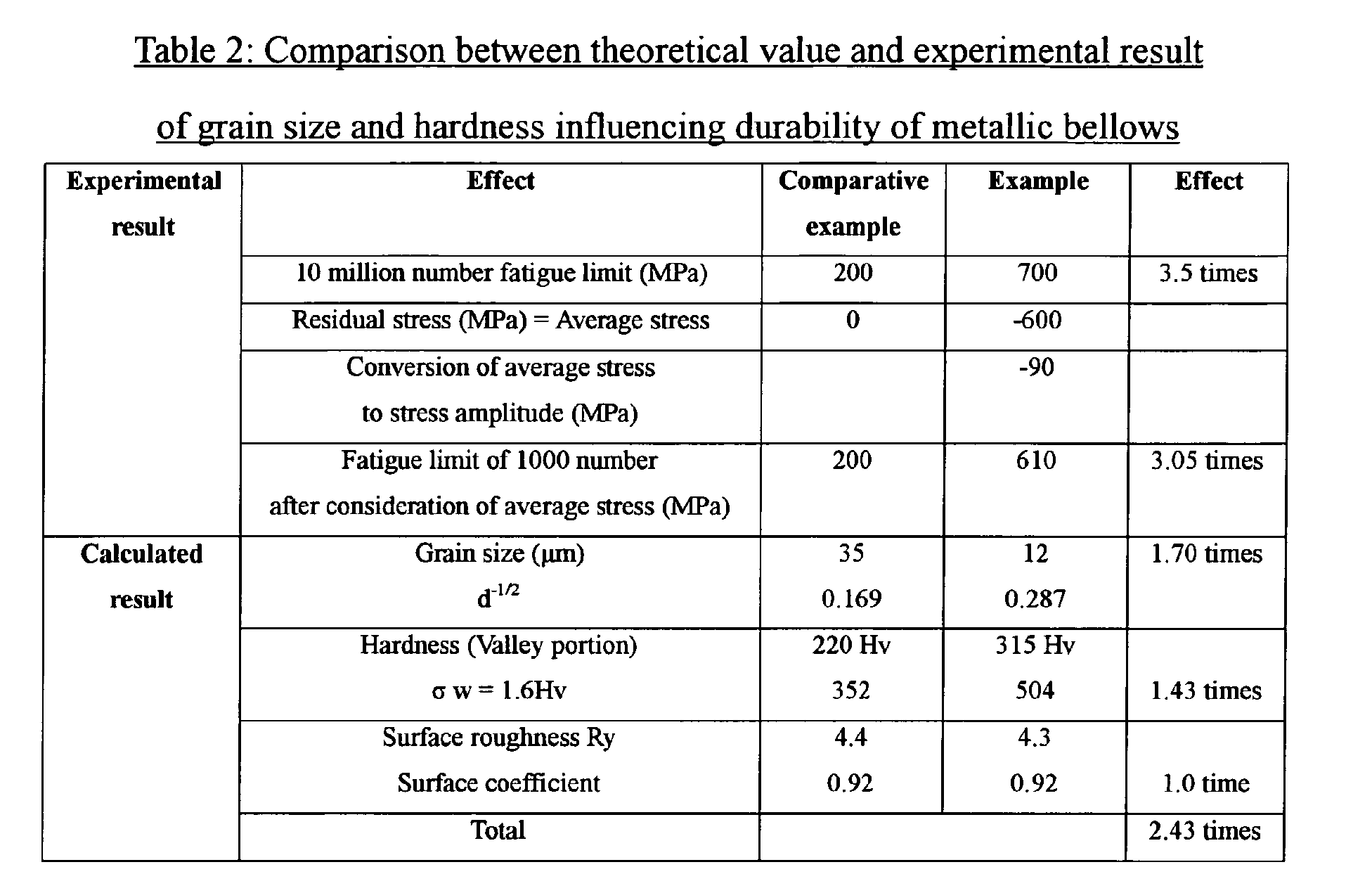
- the influence of the compressive residual stress, the grain size, and the hardness of the metallic bellows on the fatigue strength is calculated, and the example and the comparative example are compared with each other based on the calculated results.
- the calculated results are shown in Table 2.
- the compressive residual stress is substantially regarded as the average stress.
- the compressive residual stress of 600 MPa obtained in the example described above is converted into the stress amplitude of 90 MPa based on the fatigue limit diagram, and the fatigue limit of the example was improved to be 3.05 times as large as that of the comparative example.
- the grain size and the yield stress satisfy the Hall Petch relationship, and the yield stress is inversely proportional to the square root of the grain size. Assuming that the yield stress, the tensile strength, and the hardness are proportional to each other, since the hardness and the fatigue limit are proportional to each other, the fatigue limit is improved to be 1.7 times when the grain size is reduced from 3 5 ⁇ m of the comparative example to 12 ⁇ m of the example. When the hardness of the valley portion which is the origin of ruptures is increased from 220 Hv of the comparative example to 315 Hv of the example, the fatigue limit converted based on the hardness is improved to be 1.43 times.
- the fatigue limit is anticipated to be improved to be 2.43 times in theory. In contrast, actually, the fatigue limit is improved to be 3.5 times, and is larger than the theoretical value. As a result, it is thought that the effects of a combination of fining, highly strengthening, and shot peening are generated.
- the metallic bellows of the present invention can be applied to various apparatuses.
- the metallic bellows 16 can be applied to a joint as shown in Fig. 9A.
- a nipple 40 at an end thereof acts to be inclined with respect to a nipple 41 at another end thereof.
- the nipple 40 acts to move in parallel with the nipple 41 in a direction perpendicular to an axial direction.
- the metallic bellows 16 can be applied to an apparatus as shown in Fig. 9B. This apparatus shown in Fig.
- FIG. 9B is constructed such that another end of the metallic bellows 16 is supported by a cam 50 so as to be deflected and the metallic bellows 16 oscillates when the cam 50 is rotated.
- a rod 60 is tilted around a supporting point 61 so that the metallic bellows 16 is tilted.
Landscapes
- Engineering & Computer Science (AREA)
- Chemical & Material Sciences (AREA)
- Mechanical Engineering (AREA)
- General Engineering & Computer Science (AREA)
- Organic Chemistry (AREA)
- Crystallography & Structural Chemistry (AREA)
- Materials Engineering (AREA)
- Metallurgy (AREA)
- Physics & Mathematics (AREA)
- Thermal Sciences (AREA)
- Fluid Mechanics (AREA)
- Manufacturing & Machinery (AREA)
- Diaphragms And Bellows (AREA)
- Heat Treatment Of Articles (AREA)
Abstract
Description
- The present invention relates to a bellows which is used for, for example, vehicle suspension devices, gas springs, accumulators, and vacuum apparatuses, and relates to a manufacturing method for the bellows.
- Austenite stainless steel (Japanese Industrial Standard (= JIS) • SUSS04) is often used as a material for the above metallic bellows since the austenite stainless steel is easily processed. Alternatively, precipitation hardening stainless steel is used as a material for the above metallic bellows so as to improve durability of the metallic bellows. In producing a metallic bellows, first, both longitudinal sides of a stainless steel plate having an appropriate thickness are brought into contact with each other and are connected by arc welding, so that a material pipe is produced. Next, the material pipe is cut at a predetermined length and is then subjected to cold rolling using, for example, spinning working so as to have a predetermined thickness of a bellows. After that, the pipe is subjected to solution heat treatment by heating to a solution temperature thereof, and is then subjected to plastic working such as hydraulic bulging so as to be formed into a bellows. In a case in which precipitation hardening stainless steel is used, precipitation hardening heat treatment is further performed.
- In a case in which a metallic bellows is dynamically used so as to act as, for example, a spring, setting is performed so as to stabilize the loading property of the bellows after precipitation hardening heat treatment, and surface working is then performed by providing compressive residual stress to a surface of the bellows so as to improve durability thereof. The surface working is performed by shot peening in which metallic particles are shot at a surface of the bellows at high speed or by honing in which glass beads are used instead of the metallic particles (for example, paragraphs 0015 to 0022, Table 1, and Fig. 1 in Japanese Unexamined Patent Application Publication No. 2001-304412).
- Austenite stainless steel such as SUS304 is better in view of workability (for example, paragraphs 0006 to 0013, and Figs. 1, 3, 4 and 6 in Japanese Unexamined Patent Application Publication No. 2003-172449). However, a metallic bellows made of SUS304 is low in material strength, whereby the design maximum stress thereof is 850 MPa. In order to meet requirements of miniaturization and light weight of bellows in recent years, high strength materials may be used. An example of the high strength material is SUS631 of precipitation hardening semi-austenite stainless steel. When SUS 631 is used as a material for the bellows, the design stress thereof is 1100 MPa, which is about 1.3 times as large as that of a case in which SUS304 is used (for example, lower left and lower right of column 3 in Japanese Unexamined Patent Application Publication No. 1-184225).
- However, when fatigue test is performed on the bellows made of SUS631, the fatigue strength of the bellows made of SUS631 is lower than that of SUS304 as shown in Fig. 8. Generally, when the material strength is increased, the workability is reduced due to decreased elongation of the material. In particular, in the metallic bellows, since bulging having large reduction rate is performed, the fatigue strength may be reduced due to material defects such as micro-cracks generated in the bulging.
- Therefore, the present invention was made in consideration of the above problems, and an object of the present invention is to provide a metallic bellows which is composed of a material having high material strength and having high fatigue strength by preventing generation of material defects such as micro-cracks.
- The inventor has been intensively researching metallic bellows so that the fatigue strength of the metallic bellows may be improved by appropriate working on precipitation hardening stainless steel. As a result, the inventor found that average grain size, hardness between a ridge portion and a valley portion of a bellows, and compressive residual stress of surfaces of ridge portions and valley portions of a bellows have respectively an appropriate range for a metallic bellows, and the inventor thereby made the present invention.
- A metallic bellows of the present invention may be made based on the above findings. The metallic bellows composed of precipitation hardening stainless steel, comprising: ridge portions and valley portions formed alternately and continuously; an average grain size of 10 to 15 µm; and compressive residual stress of not less than 500 MPa provided to at least surfaces of the ridge portions and the valleys by surface working.
- A method of manufacturing a metallic bellows of the present invention comprises steps of: cold rolling a pipe constructed such that both edges of a plate composed of precipitation hardening stainless steel are connected to each other by welding; fining an average grain size of the precipitation hardening stainless steel to 10 to 15 µm by annealing; forming the pipe into a bellows having an axial direction; precipitation age hardening heat treating the bellows; setting the bellows by tensile loading or compressive loading in the axial direction of the bellows, so that the bellows has a predetermined height with no load; and providing compressive residual stress of not less than 500 MPa to an inside face or an outside face of the bellows by surface working.
- According to the present invention, yield stress is increased by fining the average grain size of the bellows to 10 to 15 µm, so that generation of slip bands can be inhibited. Length of cracks transmitted by about two grain sizes along slip bands can be decreased. Roughness of the surface of the bellows can be smoothed, and notch sensitivity thereof can thereby be relieved. In a case in which the average grain size of the bellows is more than 15 µm, effect of grain refining cannot be obtained. In a case in which the average grain size of the bellows is less than 10 µm, it is difficult to produce the bellows by controlling by annealing.
- According to the manufacturing method of the present invention, since compressive residual stress of not less than 500 MPa is provided to an inside face or an outside face of the bellows by surface working, fatigue strength can be further improved. When annealing temperature is reduced, the grain size of the bellows can be fined and the surface of the bellows can be fined. Therefore, generation of micro-cracks can be inhibited.
- According to the present invention, since fatigue limit is improved by fining grains of the bellows, working stress of the bellows can be set high. As a result, the number of the ridge portions of the bellows can be reduced, so that the bellows and apparatuses in which the bellows is used can be miniaturized. Material cost and manufacturing cost can be reduced because of miniaturization thereof.
-
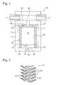
- Fig. 1 is a longitudinal section showing an accumulator of an embodiment according to the present invention.
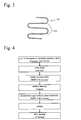
- Fig. 2 is a longitudinal section of a corrugated metallic bellows provided to an accumulator of an embodiment according to the present invention.
- Fig. 3 is a longitudinal section of a U-shaped type metallic bellows provided to an accumulator of an embodiment according to the present invention.
- Fig. 4 is a flow chart of a manufacturing process of a metallic bellows of an embodiment according to the present invention.
- Fig. 5 is a graph showing hardness distribution of a metallic bellows of an embodiment according to the present invention.
- Fig. 6 is an S-N diagram showing honing numbers of a metallic bellows of an embodiment according to the present invention and fatigue test results.
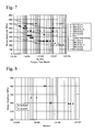
- Fig. 7 is an S-N diagram showing grain sizes of a metallic bellows of an embodiment according to the present invention and fatigue test results.
- Fig. 8 is an S-N diagram showing materials of a metallic bellows of an embodiment according to the present invention and fatigue test results.
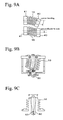
- Figs. 9 A to 9C are diagrams showing use examples of a metallic bellows of another embodiment according to the present invention.
-
- A preferred embodiment of the present invention will be described hereinafter with reference to Figs. 1 to 7. Fig. 1 shows an
accumulator 10 in which ametallic bellows 16 of the embodiment is provided. Oil generated in a pressure source (not shown in the figures) is introduced into theaccumulator 10 via aninflow opening 11 and anintroduction port 26.Gas 19 sealed in agas chamber 18 and thebellows 16 are compressed by the oil introduced in theaccumulator 10, so that pressure accumulation is performed in theaccumulator 10. The oil is supplied to a hydraulic device (not shown in the figures) via anoutflow opening 12 by the accumulated pressure of the gas so as to drive the hydraulic device. - A
pressure vessel 13 of theaccumulator 10 has a metallic cylindrical-shaped shell 14, and afirst end member 24 and asecond end member 25 which are mounted to both end portions of the metallic cylindrical-shaped shell 14 by welding, etc. Themetallic bellows 16 functions as apartition member 15 partitioning an interior of thepressure vessel 13 into ahydraulic chamber 17 and thegas chamber 18. Themetallic bellows 16 is composed of precipitation hardening stainless steel. Afixing end portion 27 of themetallic bellows 16 is connected to thesecond end portion 25 in an air-tight state by welding. Abellows cap 21 is connected to the other end side of thebellows 16 in an air-tight state by welding or caulking. Thebellows cap 21 can be elastically moved together with themetallic bellows 16 in an axial direction by pressure change of oil flowing from theinflow opening 11. - In the
gas chamber 18, an inert gas such as a nitrogen gas or a helium gas, or air which is used, depending on operation conditions, is sealed at a pressure higher than atmospheric pressure. The gas is injected from an injection opening 22 provided at thesecond end member 22. At this time, a predetermined amount of gasvolume controlling liquid 20 is also injected into thegas chamber 18. After that, the injection opening 22 is closed by aplug 23 having a male screw, etc. - A corrugated bellows shown in Fig. 2 or a U-shaped bellows 31 shown in Fig. 3 is used as the bellows 16. In the corrugated bellows,
corrugations 30 havingvalley portions 33 andridge portions 32 are closely contacted with each other when the bellows is maximally compressed. The U-shaped bellows 31 has a U-shaped cross section of valley portions and ridge portions. Aseal member 28 composed of an elastic body such as a rubber is provided on a face of a side of thehydraulic chamber 17 of the bellows cap 21. Thisseal member 28 functions as aseal mechanism 29 together with thefirst end member 24. That is, when the pressure of thehydraulic chamber 17 is reduced, theseal member 28 contacts thefirst end member 24, and the oil in thehydraulic chamber 17 is prevented from flowing to theport 26. As a result, the pressure pressed on the metallic bellows 16 by thegas chamber 18 is equal to that pressed on the metallic bellows 16 by thehydraulic chamber 17, so that the damage by the pressure from thegas chamber 18 is prevented. - Fig. 4 shows a manufacturing process for a metallic bellows. An example of a metallic bellows actually produced will be described below. First, a pipe of precipitation hardening stainless steel was subjected to cold rolling such as spinning working so as to have a predetermined wall thickness. For this example, SUS631 was used as the semi-austenite type. Alternatively, SUS633 (AM350) can be used as the semi-austenite type, and AISI1653 can be used as the austenite type. In the case of a bellows for accumulators, the precipitation hardening stainless steel having a thickness of 100 to 400 µm is used. Next, grains thereof were fined by bright annealing (BA processing). In the insides of the grains formed to be flat by cold rolling, new crystals are generated from sub-grains thereof by heating by annealing, so that grains thereof are grown. As a result, recrystallization is completed. The grains are fined so as to have an average grain size of 10 to 15 µm by controlling reduction rate of cold rolling, and temperature and time of annealing. The yield stress is increased by fining the grains, so that generation of slip bands can be inhibited. The length of cracks transmitted by about one to two grain sizes along the slip bands can be decreased. The surface roughness is smoothed, so that the notch sensitivity is relieved. In order to make the
average grain size 10 to 15 µm, the reduction rate of cold rolling (cross section reduction rate) is favorably set at 3 to 40%, the temperature of annealing is favorably set 900 to 950°C, and the annealing time is favorably set at 1 to 5 minutes. Concretely, in this example, bright annealing was performed at a temperature of 950°C for 5 minutes. For example, the reduction rate of cold rolling was set at 13%. - A metallic bellows 16 formed in the shape of a cornice by bulging as shown in Fig. 2 or 3 was obtained. In this example, after bulging, the pipe was compressed in an axial direction by pressing so as to be formed in a corrugated shape, so that the metallic bellows was produced as a corrugated bellows 30. Although the close contact of the corrugated bellows 30 can be more decreased than that of a U-shaped bellows 31, micro-cracks are easily generated in the corrugated bellows 30 since
ridge portions 32 andvalley portions 33 are greatly deformed. When a bellows is formed by increasing a size of a pipe, deformation of ridge portions is greater than that of valley portions, so that hardness of the ridge portions is greater than that of the valley portions. When a bellows is formed by reducing the size of a pipe, deformation of valley portions is greater than that of ridge portions, so that hardness of the valley portions is greater than that of the ridge portions. - Next, precipitation age hardening heat treatment was performed. Fig. 5 shows a case of a bellows made of SUS631 of precipitation hardening semi-austenite stainless steel which was heated to a temperature of 480°C for an hour. Fig. 5 shows results obtained by measuring hardness of 18 points which are positioned from the outside to the inside of the bellows by a Micro Vickers hardness tester. It is confirmed that the bellows after precipitation age hardening heat treatment is harder than before the heat treatment. Fig. 5 is an example of a bellows formed by increasing the size of the pipe, the hardness of thickness direction center portion of the ridge portion is 450 to 600 Hv, and the hardness of thickness direction center portion of the valley portion is 250 to 450 Hv.
- Next, the metallic bellows was subjected to setting by loading in an axial direction thereof so as to have a predetermined free height. After that, a first step honing was performed by shooting glass beads at high speed so as to provide residual stress to the inside face and the outer face of the metallic bellows. In the first step honing, the glass beads were about 0.1 mm, an aspirator type honing machine of air injection type was used, and the air pressure was about 0.3 MPa. As a result, compressive residual stress of not less than 500 MPa was provided to the outer surfaces of the ridge portions. Honing was performed by using glass beads having a size of 38 µm so as to decrease the high compressive residual stress and the roughness of the metallic bellows surface generated in the first step honing, so that the compressive residual stress of the metallic bellows surface was not less than 600 MPa.
- In Fig. 6, fatigue test results of a case in which the first step honing was performed (▴ plotted in Fig. 6 ) and of a case in which the second step honing was further performed (□ plotted in Fig. 6 ). In Fig. 6, 1 .E+05
denotes 1 × 10⁵. When the stress amplitude is 600 MPa, the average durability number of the metallic bellows is 3.E+05 (3 × 10⁵ ) by performing only the first step honing. When the second step honing is further performed, the average durability number of the metallic bellows is improved 9.E+06 (9 × 10⁶ ), and the metallic bellows of which the average durability number is 1.E+07 (1 × 10⁷) is not damaged to fail. - The metallic bellows produced in the above manner had an average grain size of 10 to 15 µm. Table 1 shows measured results of the hardness, the compressive residual stress, the maximum surface roughness of austenite stainless steel SUS304 of the comparative example and of precipitation hardening stainless steel SUS631 of the present invention. As shown in Table 1, the example of the present invention produced by using SUS631 has high hardness, large compressive residual stress, and low surface roughness influencing the durability in comparison with the comparative example produced by using SUS304.
Property comparison between SUS631 bellows and SUS304 bellows Item Part SUS304 SUS631 Hardness (Hv0.2) Ridge portion 350 to 370 450 to 600 Valley portion 210 to 230 250 to 450 Residual stress (MPa) Ridge portion -350 -500 Maximum surface roughness (µm) Ridge portion 5.0 4.3 Valley portion 5.3 4.3 - Fig. 7 shows fatigue test results of SUS631 and SUS304 produced under various conditions. Even in SUS631, the fatigue limit of a case of an average grain size of 35 µm (□ plotted in Fig. 7) is more decreased than that of SUS304 having an average grain size of 34 µm (▪ plotted in Fig. 7). The fatigue limits of SUS631 having an average grain size of 12 µm which was subjected to the first step honing (○ plotted in Fig. 7) and of
SUS 631 having an average grain size of 12 µm which was further subjected to the second step honing (Δ plotted in Fig. 7) are more improved than those of SUS304 having an average grain size of 12.4 µm (▴ plotted in Fig. 7) and of SUS 304 having an average grain size of 12.4 µm which was subjected to honing ( plotted in Fig. 7). - In the plots (Δ and □) of the example shown in Fig. 7, the influence of the compressive residual stress, the grain size, and the hardness of the metallic bellows on the fatigue strength is calculated, and the example and the comparative example are compared with each other based on the calculated results. The calculated results are shown in Table 2. The compressive residual stress is substantially regarded as the average stress. In this case, the compressive residual stress of 600 MPa obtained in the example described above is converted into the stress amplitude of 90 MPa based on the fatigue limit diagram, and the fatigue limit of the example was improved to be 3.05 times as large as that of the comparative example.
- The grain size and the yield stress satisfy the Hall Petch relationship, and the yield stress is inversely proportional to the square root of the grain size. Assuming that the yield stress, the tensile strength, and the hardness are proportional to each other, since the hardness and the fatigue limit are proportional to each other, the fatigue limit is improved to be 1.7 times when the grain size is reduced from 3 5 µm of the comparative example to 12 µm of the example. When the hardness of the valley portion which is the origin of ruptures is increased from 220 Hv of the comparative example to 315 Hv of the example, the fatigue limit converted based on the hardness is improved to be 1.43 times. Since there is almost no difference in the surface roughness between the comparative example and the example, the influence thereof on the fatigue limit can be neglected. Based on the above results, the fatigue limit is anticipated to be improved to be 2.43 times in theory. In contrast, actually, the fatigue limit is improved to be 3.5 times, and is larger than the theoretical value. As a result, it is thought that the effects of a combination of fining, highly strengthening, and shot peening are generated.
- Although the above embodiment is an example of the metallic bellows of the present invention applied to an accumulator, the metallic bellows of the present invention can be applied to various apparatuses. For example, the metallic bellows 16 can be applied to a joint as shown in Fig. 9A. In this joint, a
nipple 40 at an end thereof acts to be inclined with respect to anipple 41 at another end thereof. Alternatively, thenipple 40 acts to move in parallel with thenipple 41 in a direction perpendicular to an axial direction. The metallic bellows 16 can be applied to an apparatus as shown in Fig. 9B. This apparatus shown in Fig. 9B is constructed such that another end of the metallic bellows 16 is supported by acam 50 so as to be deflected and the metallic bellows 16 oscillates when thecam 50 is rotated. In an apparatus shown in Fig. 9C, arod 60 is tilted around a supportingpoint 61 so that the metallic bellows 16 is tilted.
Claims (7)
- A metallic bellows composed of precipitation hardening stainless steel, comprising:ridge portions and valley portions formed alternately and continuously;an average grain size of 10 to 15 µm; andcompressive residual stress of not less than 500 MPa provided to at least surfaces of the ridge portions and the valleys by surface working.
- The metallic bellows according to claim 1, wherein the bellows has a hardness of 450 to 600 Hv at a thickness direction center portion of the ridge potion and has a hardness of 250 to 450 Hv at a thickness direction center portion of the valley portion.
- The metallic bellows according to claim 1 or 2 , wherein the bellows is a corrugated bellows in which the valley portion and the ridge portion have a corrugation-shaped cross section, and the ridge portions are closely contacted with each other and the valley portions are closely contacted with each other when the bellows is maximally compressed.
- The metallic bellows according to one of claims 1 to 3, wherein a first step surface working is performed by shooting particles to a surface of the bellows, the particle having a predetermined average particle size, and thena second step surface working is performed by shooting particles to the surface of the bellows, the particles having an average particle size smaller than that of the particle used in the first step surface working.
- The metallic bellows according to claim 4, wherein the first step surface working and the second step surface working are performed on an outside face and an inside face of the metallic bellows.
- An accumulator comprising:the metallic bellows according to one of claims 1 to 5.
- A method of manufacturing metallic bellows, comprising steps of:cold rolling a pipe constructed such that both edges of a plate composed of precipitation hardening stainless steel are connected to each other by welding;fining an average grain size of the precipitation hardening stainless steel to 10 to 15 µm by annealing;forming the pipe into a bellows having an axial direction;precipitation age hardening heat treating on the bellows;setting the bellows by tensile loading or compressive loading in the axial direction of the bellows, so that the bellows has a predetermined height with no load; andproviding compressive residual stress of not less than 500 MPa to an inside face or an outside face of the bellows by surface working.
Applications Claiming Priority (2)
| Application Number | Priority Date | Filing Date | Title |
|---|---|---|---|
| JP2003378977 | 2003-11-07 | ||
| JP2003378977A JP4311639B2 (en) | 2003-11-07 | 2003-11-07 | Method for producing metal bellows |
Publications (2)
| Publication Number | Publication Date |
|---|---|
| EP1529993A1 true EP1529993A1 (en) | 2005-05-11 |
| EP1529993B1 EP1529993B1 (en) | 2007-03-14 |
Family
ID=34431365
Family Applications (1)
| Application Number | Title | Priority Date | Filing Date |
|---|---|---|---|
| EP04026284A Expired - Lifetime EP1529993B1 (en) | 2003-11-07 | 2004-11-05 | Metallic bellows, manufacturing method therefor, and accumulator therewith |
Country Status (4)
| Country | Link |
|---|---|
| US (1) | US7399372B2 (en) |
| EP (1) | EP1529993B1 (en) |
| JP (1) | JP4311639B2 (en) |
| DE (1) | DE602004005288T2 (en) |
Cited By (4)
| Publication number | Priority date | Publication date | Assignee | Title |
|---|---|---|---|---|
| EP1889936A4 (en) * | 2005-06-09 | 2009-05-27 | Jfe Steel Corp | FERRITE STAINLESS STEEL SHEET FOR BELLOW PIPES |
| CN103459618A (en) * | 2011-02-18 | 2013-12-18 | 悬挂系统股份有限公司 | Method for manufacturing high-strength steel sheet parts subject in use to fatigue stresses |
| KR102119263B1 (en) * | 2019-12-03 | 2020-06-04 | 한국씰마스타주식회사 | Pressure Bellows and its Manufacturing method |
| CN120023228A (en) * | 2025-03-17 | 2025-05-23 | 上海真兰仪表科技股份有限公司 | A processing method for ultra-flexible tube |
Families Citing this family (14)
| Publication number | Priority date | Publication date | Assignee | Title |
|---|---|---|---|---|
| JP2008546204A (en) * | 2005-06-03 | 2008-12-18 | フジフィルム・エレクトロニック・マテリアルズ・ユーエスエイ・インコーポレイテッド | Pretreatment composition |
| JP2007218231A (en) * | 2006-02-20 | 2007-08-30 | Nhk Spring Co Ltd | Spring device and valve mechanism of internal combustion engine using the same |
| JP2008119742A (en) * | 2006-11-10 | 2008-05-29 | Showarasenkan Seisakusho Co Ltd | Method for manufacturing long metallic bellows pipe, and long metallic bellows pipe |
| JP5005494B2 (en) * | 2007-10-18 | 2012-08-22 | 日立Geニュークリア・エナジー株式会社 | Bellows, universal bellows using the bellows, piping system for fast breeder reactor, and fast breeder reactor facility |
| FR2953594B1 (en) * | 2009-12-04 | 2012-09-14 | Olaer Ind Sa | TEST DEVICE FOR FLEXIBLE SEPARATOR |
| DE102014204348A1 (en) * | 2014-03-10 | 2015-09-10 | Wika Alexander Wiegand Se & Co. Kg | STEEL MEASURING ELEMENT WITH HARDENED EDGE ZONE |
| WO2016072323A1 (en) * | 2014-11-05 | 2016-05-12 | イーグル工業株式会社 | Metal bellows |
| DE102015206251A1 (en) * | 2015-04-08 | 2016-10-13 | OBE OHNMACHT & BAUMGäRTNER GMBH & CO. KG | Metal bellows and process for its manufacture |
| CN108138957B (en) * | 2015-09-23 | 2020-05-12 | 伊格尔工业股份有限公司 | Metal corrugated pipe |
| US9670979B1 (en) | 2016-05-13 | 2017-06-06 | Liquidspring Technologies, Inc. | Resilient expandable pressure vessel |
| CN110431335B (en) * | 2017-03-02 | 2020-10-27 | 伊格尔工业股份有限公司 | Corrugated pipe |
| US10994916B2 (en) | 2017-11-30 | 2021-05-04 | Liquitek Llc | Sleeve member, container assembly kit including same, and associated method of manufacturing a sleeve member |
| DE102021002971A1 (en) * | 2021-06-10 | 2022-12-15 | Hydac Technology Gmbh | Separating element and hydraulic accumulator with such a separating element |
| CN116046550B (en) * | 2023-01-05 | 2025-10-28 | 江苏科技大学 | A design method for three-dimensional strain forming limit path of high-pressure internal bulging of tubes |
Citations (5)
| Publication number | Priority date | Publication date | Assignee | Title |
|---|---|---|---|---|
| US4369074A (en) * | 1981-06-29 | 1983-01-18 | Bodyako Mikhail N | Method of producing bellows from metal alloys |
| JPH01184225A (en) | 1988-01-19 | 1989-07-21 | Nhk Spring Co Ltd | Metallic bellows and production of said bellows |
| JP2001304412A (en) | 2000-04-20 | 2001-10-31 | Nhk Spring Co Ltd | Metal bellows and method of manufacturing the same |
| DE10027541A1 (en) * | 2000-06-02 | 2001-12-13 | Eurocopter Deutschland | High-strength metal bellows manufacturing process involves shotblasting bellows after heat treatment at least in one region of inner flap and one region of outer flap |
| JP2003172449A (en) | 2001-12-07 | 2003-06-20 | Nhk Spring Co Ltd | Stainless steel bellows, accumulator using the same, and method for manufacturing stainless steel pipe |
Family Cites Families (2)
| Publication number | Priority date | Publication date | Assignee | Title |
|---|---|---|---|---|
| JPH08176750A (en) * | 1994-12-28 | 1996-07-09 | Nippon Steel Corp | Ferritic stainless steel for bellows processing |
| DE60106812T2 (en) * | 2000-06-16 | 2005-10-27 | NHK Spring Co., Ltd., Yokohama | Method for producing metallic bellows |
-
2003
- 2003-11-07 JP JP2003378977A patent/JP4311639B2/en not_active Expired - Lifetime
-
2004
- 2004-11-01 US US10/976,764 patent/US7399372B2/en not_active Expired - Lifetime
- 2004-11-05 EP EP04026284A patent/EP1529993B1/en not_active Expired - Lifetime
- 2004-11-05 DE DE602004005288T patent/DE602004005288T2/en not_active Expired - Lifetime
Patent Citations (5)
| Publication number | Priority date | Publication date | Assignee | Title |
|---|---|---|---|---|
| US4369074A (en) * | 1981-06-29 | 1983-01-18 | Bodyako Mikhail N | Method of producing bellows from metal alloys |
| JPH01184225A (en) | 1988-01-19 | 1989-07-21 | Nhk Spring Co Ltd | Metallic bellows and production of said bellows |
| JP2001304412A (en) | 2000-04-20 | 2001-10-31 | Nhk Spring Co Ltd | Metal bellows and method of manufacturing the same |
| DE10027541A1 (en) * | 2000-06-02 | 2001-12-13 | Eurocopter Deutschland | High-strength metal bellows manufacturing process involves shotblasting bellows after heat treatment at least in one region of inner flap and one region of outer flap |
| JP2003172449A (en) | 2001-12-07 | 2003-06-20 | Nhk Spring Co Ltd | Stainless steel bellows, accumulator using the same, and method for manufacturing stainless steel pipe |
Non-Patent Citations (1)
| Title |
|---|
| PATENT ABSTRACTS OF JAPAN vol. 2002, no. 02 2 April 2002 (2002-04-02) * |
Cited By (4)
| Publication number | Priority date | Publication date | Assignee | Title |
|---|---|---|---|---|
| EP1889936A4 (en) * | 2005-06-09 | 2009-05-27 | Jfe Steel Corp | FERRITE STAINLESS STEEL SHEET FOR BELLOW PIPES |
| CN103459618A (en) * | 2011-02-18 | 2013-12-18 | 悬挂系统股份有限公司 | Method for manufacturing high-strength steel sheet parts subject in use to fatigue stresses |
| KR102119263B1 (en) * | 2019-12-03 | 2020-06-04 | 한국씰마스타주식회사 | Pressure Bellows and its Manufacturing method |
| CN120023228A (en) * | 2025-03-17 | 2025-05-23 | 上海真兰仪表科技股份有限公司 | A processing method for ultra-flexible tube |
Also Published As
| Publication number | Publication date |
|---|---|
| US20050098244A1 (en) | 2005-05-12 |
| DE602004005288D1 (en) | 2007-04-26 |
| JP4311639B2 (en) | 2009-08-12 |
| EP1529993B1 (en) | 2007-03-14 |
| US7399372B2 (en) | 2008-07-15 |
| JP2005140285A (en) | 2005-06-02 |
| DE602004005288T2 (en) | 2007-12-20 |
Similar Documents
| Publication | Publication Date | Title |
|---|---|---|
| US7399372B2 (en) | Method for manufacturing metallic bellows | |
| US4354371A (en) | Method of prestressing the working surfaces of pressure chambers or cylinders | |
| EP0757196A1 (en) | Diaphragm valve | |
| KR20020072212A (en) | Hollow stabilizer and manufacturing method thereof | |
| US6502833B1 (en) | Metal C-shaped ring gasket | |
| Furuya et al. | Inclusion-controlled fatigue properties of 1800 MPA-class spring steels | |
| Ogata | Simple mechanical testing method to evaluate influence of high pressure hydrogen gas | |
| US5078582A (en) | Reciprocatory piston type compressor having a noise and vibration suppressed discharge valve mechanism | |
| EP3608057A1 (en) | Hollow spring and method for manufacturing same | |
| US6695201B2 (en) | Stress relieved lower shell for sealed compressors | |
| CN108869594A (en) | A kind of high stress, the variable cross-section single-leaf spring and its manufacturing method of high life | |
| US20050118041A1 (en) | Diaphragm pump | |
| WO2023112390A1 (en) | Method for suppressing fatigue crack progression in bent section of metal plate and automobile component | |
| EP1889936B1 (en) | Ferrite stainless steel sheet for bellows stock pipe | |
| JP3227492B2 (en) | Spring shot peening method and spring product | |
| JP3998733B2 (en) | High spring resistance and fatigue resistance coil spring | |
| CN110475626A (en) | Hollow stabilizer, stabilizer manufacturing device and hollow stabilizer manufacturing method | |
| EP3865738A1 (en) | Metal gasket | |
| CN114025896B (en) | Hollow spring and method for manufacturing same | |
| JP2003172449A (en) | Stainless steel bellows, accumulator using the same, and method for manufacturing stainless steel pipe | |
| JP2001079766A (en) | Shot peening projection material | |
| JPH07317925A (en) | Diaphragm seal valve and its metal diaphragm | |
| JP2003194225A (en) | Metal gasket | |
| CN101801607A (en) | Method and system for processing a sheet of material | |
| JP4389241B2 (en) | Metal ring gasket |
Legal Events
| Date | Code | Title | Description |
|---|---|---|---|
| PUAI | Public reference made under article 153(3) epc to a published international application that has entered the european phase |
Free format text: ORIGINAL CODE: 0009012 |
|
| AK | Designated contracting states |
Kind code of ref document: A1 Designated state(s): AT BE BG CH CY CZ DE DK EE ES FI FR GB GR HU IE IS IT LI LU MC NL PL PT RO SE SI SK TR |
|
| AX | Request for extension of the european patent |
Extension state: AL HR LT LV MK YU |
|
| 17P | Request for examination filed |
Effective date: 20050614 |
|
| AKX | Designation fees paid |
Designated state(s): DE FR GB |
|
| RIN1 | Information on inventor provided before grant (corrected) |
Inventor name: OKADA, HIDEKI |
|
| GRAP | Despatch of communication of intention to grant a patent |
Free format text: ORIGINAL CODE: EPIDOSNIGR1 |
|
| GRAS | Grant fee paid |
Free format text: ORIGINAL CODE: EPIDOSNIGR3 |
|
| GRAA | (expected) grant |
Free format text: ORIGINAL CODE: 0009210 |
|
| AK | Designated contracting states |
Kind code of ref document: B1 Designated state(s): DE FR GB |
|
| REG | Reference to a national code |
Ref country code: GB Ref legal event code: FG4D |
|
| REF | Corresponds to: |
Ref document number: 602004005288 Country of ref document: DE Date of ref document: 20070426 Kind code of ref document: P |
|
| REG | Reference to a national code |
Ref country code: DE Ref legal event code: R096 Ref document number: 602004005288 Country of ref document: DE Effective date: 20070426 |
|
| PLBE | No opposition filed within time limit |
Free format text: ORIGINAL CODE: 0009261 |
|
| STAA | Information on the status of an ep patent application or granted ep patent |
Free format text: STATUS: NO OPPOSITION FILED WITHIN TIME LIMIT |
|
| 26N | No opposition filed |
Effective date: 20071217 |
|
| REG | Reference to a national code |
Ref country code: DE Ref legal event code: R097 Ref document number: 602004005288 Country of ref document: DE Effective date: 20071217 |
|
| REG | Reference to a national code |
Ref country code: FR Ref legal event code: PLFP Year of fee payment: 12 |
|
| REG | Reference to a national code |
Ref country code: FR Ref legal event code: PLFP Year of fee payment: 13 |
|
| REG | Reference to a national code |
Ref country code: FR Ref legal event code: PLFP Year of fee payment: 14 |
|
| REG | Reference to a national code |
Ref country code: FR Ref legal event code: PLFP Year of fee payment: 15 |
|
| P01 | Opt-out of the competence of the unified patent court (upc) registered |
Effective date: 20230515 |
|
| PGFP | Annual fee paid to national office [announced via postgrant information from national office to epo] |
Ref country code: GB Payment date: 20230928 Year of fee payment: 20 |
|
| PGFP | Annual fee paid to national office [announced via postgrant information from national office to epo] |
Ref country code: FR Payment date: 20230929 Year of fee payment: 20 |
|
| PGFP | Annual fee paid to national office [announced via postgrant information from national office to epo] |
Ref country code: DE Payment date: 20230929 Year of fee payment: 20 |
|
| REG | Reference to a national code |
Ref country code: DE Ref legal event code: R071 Ref document number: 602004005288 Country of ref document: DE |
|
| REG | Reference to a national code |
Ref country code: GB Ref legal event code: PE20 Expiry date: 20241104 |
|
| PG25 | Lapsed in a contracting state [announced via postgrant information from national office to epo] |
Ref country code: GB Free format text: LAPSE BECAUSE OF EXPIRATION OF PROTECTION Effective date: 20241104 |
|
| PG25 | Lapsed in a contracting state [announced via postgrant information from national office to epo] |
Ref country code: GB Free format text: LAPSE BECAUSE OF EXPIRATION OF PROTECTION Effective date: 20241104 |