EP1529926B1 - Spring and damper system for turbine shrouds - Google Patents
Spring and damper system for turbine shrouds Download PDFInfo
- Publication number
- EP1529926B1 EP1529926B1 EP04256829.5A EP04256829A EP1529926B1 EP 1529926 B1 EP1529926 B1 EP 1529926B1 EP 04256829 A EP04256829 A EP 04256829A EP 1529926 B1 EP1529926 B1 EP 1529926B1
- Authority
- EP
- European Patent Office
- Prior art keywords
- shroud
- spring
- damper block
- piston
- damper
- Prior art date
- Legal status (The legal status is an assumption and is not a legal conclusion. Google has not performed a legal analysis and makes no representation as to the accuracy of the status listed.)
- Expired - Lifetime
Links
- 238000013016 damping Methods 0.000 claims description 23
- 230000007246 mechanism Effects 0.000 claims description 17
- 238000001816 cooling Methods 0.000 claims description 10
- 230000008878 coupling Effects 0.000 claims description 10
- 238000010168 coupling process Methods 0.000 claims description 10
- 238000005859 coupling reaction Methods 0.000 claims description 10
- 239000002826 coolant Substances 0.000 claims description 8
- 230000003647 oxidation Effects 0.000 claims description 3
- 238000007254 oxidation reaction Methods 0.000 claims description 3
- 239000007769 metal material Substances 0.000 claims description 2
- 229910010293 ceramic material Inorganic materials 0.000 claims 1
- 238000011144 upstream manufacturing Methods 0.000 claims 1
- 239000000919 ceramic Substances 0.000 description 14
- 239000007789 gas Substances 0.000 description 12
- 239000002131 composite material Substances 0.000 description 9
- 238000012546 transfer Methods 0.000 description 7
- 239000000463 material Substances 0.000 description 5
- 230000007774 longterm Effects 0.000 description 3
- 230000036316 preload Effects 0.000 description 3
- 230000014759 maintenance of location Effects 0.000 description 2
- 238000012552 review Methods 0.000 description 2
- 230000002411 adverse Effects 0.000 description 1
- 239000011153 ceramic matrix composite Substances 0.000 description 1
- 230000000295 complement effect Effects 0.000 description 1
- 230000001143 conditioned effect Effects 0.000 description 1
- 230000001419 dependent effect Effects 0.000 description 1
- 238000007689 inspection Methods 0.000 description 1
- 238000012423 maintenance Methods 0.000 description 1
- 239000002184 metal Substances 0.000 description 1
- 229910001092 metal group alloy Inorganic materials 0.000 description 1
- 238000000034 method Methods 0.000 description 1
- 150000004767 nitrides Chemical class 0.000 description 1
- 229920001296 polysiloxane Polymers 0.000 description 1
- 230000000717 retained effect Effects 0.000 description 1
- 229910000601 superalloy Inorganic materials 0.000 description 1
- 230000003746 surface roughness Effects 0.000 description 1
- 238000012360 testing method Methods 0.000 description 1
- 238000003466 welding Methods 0.000 description 1
Images


Classifications
-
- F—MECHANICAL ENGINEERING; LIGHTING; HEATING; WEAPONS; BLASTING
- F01—MACHINES OR ENGINES IN GENERAL; ENGINE PLANTS IN GENERAL; STEAM ENGINES
- F01D—NON-POSITIVE DISPLACEMENT MACHINES OR ENGINES, e.g. STEAM TURBINES
- F01D25/00—Component parts, details, or accessories, not provided for in, or of interest apart from, other groups
- F01D25/005—Selecting particular materials
-
- F—MECHANICAL ENGINEERING; LIGHTING; HEATING; WEAPONS; BLASTING
- F01—MACHINES OR ENGINES IN GENERAL; ENGINE PLANTS IN GENERAL; STEAM ENGINES
- F01D—NON-POSITIVE DISPLACEMENT MACHINES OR ENGINES, e.g. STEAM TURBINES
- F01D11/00—Preventing or minimising internal leakage of working-fluid, e.g. between stages
- F01D11/08—Preventing or minimising internal leakage of working-fluid, e.g. between stages for sealing space between rotor blade tips and stator
-
- F—MECHANICAL ENGINEERING; LIGHTING; HEATING; WEAPONS; BLASTING
- F01—MACHINES OR ENGINES IN GENERAL; ENGINE PLANTS IN GENERAL; STEAM ENGINES
- F01D—NON-POSITIVE DISPLACEMENT MACHINES OR ENGINES, e.g. STEAM TURBINES
- F01D25/00—Component parts, details, or accessories, not provided for in, or of interest apart from, other groups
- F01D25/04—Antivibration arrangements
-
- F—MECHANICAL ENGINEERING; LIGHTING; HEATING; WEAPONS; BLASTING
- F01—MACHINES OR ENGINES IN GENERAL; ENGINE PLANTS IN GENERAL; STEAM ENGINES
- F01D—NON-POSITIVE DISPLACEMENT MACHINES OR ENGINES, e.g. STEAM TURBINES
- F01D25/00—Component parts, details, or accessories, not provided for in, or of interest apart from, other groups
- F01D25/24—Casings; Casing parts, e.g. diaphragms, casing fastenings
- F01D25/246—Fastening of diaphragms or stator-rings
-
- F—MECHANICAL ENGINEERING; LIGHTING; HEATING; WEAPONS; BLASTING
- F01—MACHINES OR ENGINES IN GENERAL; ENGINE PLANTS IN GENERAL; STEAM ENGINES
- F01D—NON-POSITIVE DISPLACEMENT MACHINES OR ENGINES, e.g. STEAM TURBINES
- F01D9/00—Stators
- F01D9/02—Nozzles; Nozzle boxes; Stator blades; Guide conduits, e.g. individual nozzles
- F01D9/04—Nozzles; Nozzle boxes; Stator blades; Guide conduits, e.g. individual nozzles forming ring or sector
Definitions
- the present invention relates to a damping system for damping vibration of shrouds surrounding rotating components in a hot gas path of a turbine and particularly relates to a spring mass damping system for interfacing with a ceramic shroud and tuning the shroud to minimize vibratory response from pressure pulses in the hot gas path as each turbine blade passes the individual shroud.
- Ceramic matrix composites offer advantages as a material of choice for shrouds in a turbine for interfacing with the hot gas path.
- the ceramic composites offer high material temperature capability. It will be appreciated that the shrouds are subject to vibration due to the pressure pulses of the hot gases as each blade or bucket passes the shroud. Moreover, because of this proximity to high-speed rotation of the buckets, the vibration may be at or near resonant frequencies and thus require damping to maintain life expectancy during long-term commercial operation of the turbine. Ceramic composites, however, are difficult to attach and have failure mechanisms such as wear, oxidation due to ionic transfer with metal, stress concentration and damage to the ceramic composite when configuring the composite for attachment to the metallic components. Accordingly, there is a need for responding to dynamics-related issues relating to the attachment of ceramic composite shrouds to metallic components of the turbine to minimize adverse modal response.
- US 5429477 describes a vibration damper for a rotor housing including a rubber-elastic damping band that encircles the outer circumference of the rotor housing in a contour fitting manner.
- a clamping band encircles the damping band and secures the damping band to the housing.
- the clamping band is made of a material having a different modulus of elasticity than the material of the rotor housing, which achieves a detuning of the vibrational system including the rotor housing and the vibration damper as components. Such a detuning reduces the vibrational tendency of the rotor housing.
- the clamping band includes a tension adjustment element that is adjustable and releasable so that the clamping band and the entire vibration damper may easily be removed from the housing for carrying out maintenance and inspection procedures.
- EP 1362983 describes a gas turbine having a metallic outer shroud and a ceramic inner shroud secured to the outer shroud by hooks carried on the outer shroud.
- a pin and spring system are provided to hold the ceramic inner shroud against the forward hook of the outer shroud and an anti-rotation pin is provided to trap the aft bend of the ceramic inner shroud against the aft hook.
- the gas turbine further includes a damping spring and pin system, disposed between a heat shield within the outer shroud, and the ceramic inner shroud, to provide damping of the inner shroud.
- the present invention resides in a damper system for a stage of a turbine as defined in the appended claims.
- an attachment mechanism is provided between a ceramic composite shroud and a metallic support structure which utilizes the pressure distribution applied to the shroud, coupled with a loading on the shroud to tune the shroud to minimize damaging vibratory response from pressure pulses of the hot gases as the buckets pass the shrouds.
- the damping system includes a ceramic composite shroud/damping block, a damper load transfer mechanism and a damping mechanism.
- the damper block includes at least three projections for engaging the backside of the shroud, thereby spacing the damper block surface from the backside of the shroud, affording a convective insulating layer, and reducing heat load on the damper block.
- the three projections are specifically located along the damper block to tune the dynamic response of the system.
- the load transfer mechanism includes a piston having a ball-and-socket coupling with the damper block along with a spring damping mechanism in the socket region of the outer shroud block.
- the ball-and-socket coupling uses a pin retention system enabling relative movement between the piston and damper block.
- the piston engages the spring through a thermally insulating washer and preferably also through a metallic washer, both being encapsulated within a cup supplied with a cooling medium.
- the cooling medium maintains the temperature of the spring below a temperature limit in order to maintain positive preload on the shroud.
- FIG. 1 is a view in a circumferential direction and Figure 2 is a view in an axial forward direction opposite to the direction of flow of the hot gas stream through the turbine.
- the shroud block 10 carries preferably three individual shrouds 12. It will be appreciated that a plurality of shroud blocks 10 are disposed in a circumferential array about the turbine axis and mount a plurality of shrouds 12 surrounding and forming a part of the hot gas path flowing through the turbine.
- the shrouds 12 are formed of a ceramic composite, are secured by bolts, not shown, to the shroud blocks 10, and have a first inner surface 11 ( Figure 2 ) in contact with the hot gases of the hot gas path.
- the damper system of the present invention includes a damper block/shroud interface, a damper load transfer mechanism and a damping mechanism.
- the damper block/shroud interface includes a damper block 16 formed of a metallic material, e.g., PM2000, which is a superalloy material having high temperature use limits of up to 1216°C (2200°F).
- the radially inwardly facing surface 18 ( Figure 3 ) of the damper block 16 includes at least three projections 20 which engage a backside surface 22 ( Figure 1 ) of the shroud 12. Projections 20 are sized to distribute sufficient load to the shroud 12, while minimizing susceptibility to wear and binding between the shroud 12 and damper block 16.
- the location of the projections 20 are dependent upon the desired system dynamic response which is determined by system natural frequency vibratory response testing and modal analysis. Consequently, the locations of the projections 20 are predetermined.
- the projections 20a and 20b are located along the forward edge of the damper block 16 and adjacent the opposite sides thereof. Consequently, the projections 20a and 20b are symmetrically located along the forward edge of the damper block 16 relative to the sides.
- the remaining projection 20c is located adjacent the rear edge of the damper block 16 and toward one side thereof.
- the rear projection 20c is located along the rear edge of block 16 and asymmetrically relative to the sides of the damper block 16.
- the projections 20 provide a substantial insulating space, i.e., a convective insulating layer, between the damper block 16 and the backside of the shroud 12, which reduces the heat load on the damper block.
- the projections 20 also compensate for the surface roughness variation commonly associated with ceramic composite shroud surfaces.
- the damper load transfer mechanism generally designated 30, includes a piston assembly having a piston 32 which passes through an aperture 34 formed in the shroud block 10.
- the radially inner or distal end of the piston 32 terminates in a ball 36 received within a complementary socket 38 formed in the damper block 16 thereby forming a ball-and-socket coupling 39.
- the sides of the piston spaced back from the ball 36 are of lesser diameter than the ball and pins 40 are secured, for example, by welding, to the damper block 16 along opposite sides of the piston to retain the coupling between the damper block 16 and the piston 32.
- the coupling enables relative movement between the piston 32 and block 16.
- a central cooling passage 42 is formed axially along the piston, terminating in a pair of film-cooling holes 44 for providing a cooling medium, e.g., compressor discharge air, into the ball-and-socket coupling.
- the cooling medium e.g., compressor discharge air
- the sides of the piston are provided with at least a pair of radially outwardly projecting, axially spaced lands 48.
- the lands 48 reduce the potential for the shaft to bind with the aperture of the damper block 10 due to oxidation and/or wear during long-term continuous operation.
- the damper load transfer mechanism also includes superposed metallic and thermally insulated washers 50 and 52, respectively.
- the washers are disposed in a cup 54 carried by the piston 32.
- the metallic washer 50 provides a support for the thermally insulating washer 52, which preferably is formed of a monolithic ceramic silicone nitride.
- the thermally insulative washer 52 blocks the conductive heat path of the piston via contact with the damper block 12.
- the damping mechanism includes a spring 60.
- the spring is pre-conditioned at temperature and load prior to assembly as a means to ensure consistency in structural compliance.
- the spring 60 is mounted within a cup-shaped housing 62 formed along the backside of the shroud block 10.
- the spring is preloaded to engage at one end the insulative washer 52 to bias the piston 32 radially inwardly.
- the opposite end of spring 60 engages a cap 64 secured, for example, by threads to the housing 62.
- the cap 64 has a central opening or passage 67 enabling cooling flow from compressor discharge air to flow within the housing to maintain the temperature of the spring below a predetermined temperature.
- the spring is made from low-temperature metal alloys to maintain a positive preload on the piston and therefore is kept below a predetermined specific temperature limit.
- the cooling medium is also supplied to the cooling passage 42 and the film-cooling holes 44 to cool the ball-and-socket coupling.
- a passageway 65 is provided to exhaust the spent cooling medium.
- the spring 60 of the damping mechanism maintains a radial inwardly directed force on the piston 32 and hence on the damper block 16.
- the damper block 16 bears against the backside surface 22 of the shroud 12 to dampen vibration and particularly to avoid vibratory response at or near resonant frequencies.
Landscapes
- Engineering & Computer Science (AREA)
- Mechanical Engineering (AREA)
- General Engineering & Computer Science (AREA)
- Chemical & Material Sciences (AREA)
- Materials Engineering (AREA)
- Turbine Rotor Nozzle Sealing (AREA)
- Pistons, Piston Rings, And Cylinders (AREA)
- Springs (AREA)
Description
- The present invention relates to a damping system for damping vibration of shrouds surrounding rotating components in a hot gas path of a turbine and particularly relates to a spring mass damping system for interfacing with a ceramic shroud and tuning the shroud to minimize vibratory response from pressure pulses in the hot gas path as each turbine blade passes the individual shroud.
- Ceramic matrix composites offer advantages as a material of choice for shrouds in a turbine for interfacing with the hot gas path. The ceramic composites offer high material temperature capability. It will be appreciated that the shrouds are subject to vibration due to the pressure pulses of the hot gases as each blade or bucket passes the shroud. Moreover, because of this proximity to high-speed rotation of the buckets, the vibration may be at or near resonant frequencies and thus require damping to maintain life expectancy during long-term commercial operation of the turbine. Ceramic composites, however, are difficult to attach and have failure mechanisms such as wear, oxidation due to ionic transfer with metal, stress concentration and damage to the ceramic composite when configuring the composite for attachment to the metallic components. Accordingly, there is a need for responding to dynamics-related issues relating to the attachment of ceramic composite shrouds to metallic components of the turbine to minimize adverse modal response.
-
US 5429477 describes a vibration damper for a rotor housing including a rubber-elastic damping band that encircles the outer circumference of the rotor housing in a contour fitting manner. A clamping band encircles the damping band and secures the damping band to the housing. The clamping band is made of a material having a different modulus of elasticity than the material of the rotor housing, which achieves a detuning of the vibrational system including the rotor housing and the vibration damper as components. Such a detuning reduces the vibrational tendency of the rotor housing. Frictional rubbing between the damping band and the housing surface, and between the damping band and the clamping band effectively damps or dissipates the energy of any vibration that does occur. The clamping band includes a tension adjustment element that is adjustable and releasable so that the clamping band and the entire vibration damper may easily be removed from the housing for carrying out maintenance and inspection procedures. -
EP 1362983 describes a gas turbine having a metallic outer shroud and a ceramic inner shroud secured to the outer shroud by hooks carried on the outer shroud. A pin and spring system are provided to hold the ceramic inner shroud against the forward hook of the outer shroud and an anti-rotation pin is provided to trap the aft bend of the ceramic inner shroud against the aft hook. The gas turbine further includes a damping spring and pin system, disposed between a heat shield within the outer shroud, and the ceramic inner shroud, to provide damping of the inner shroud. - The present invention resides in a damper system for a stage of a turbine as defined in the appended claims.
- In summary, an attachment mechanism is provided between a ceramic composite shroud and a metallic support structure which utilizes the pressure distribution applied to the shroud, coupled with a loading on the shroud to tune the shroud to minimize damaging vibratory response from pressure pulses of the hot gases as the buckets pass the shrouds. To accomplish the foregoing, the damping system includes a ceramic composite shroud/damping block, a damper load transfer mechanism and a damping mechanism. The damper block includes at least three projections for engaging the backside of the shroud, thereby spacing the damper block surface from the backside of the shroud, affording a convective insulating layer, and reducing heat load on the damper block. The three projections are specifically located along the damper block to tune the dynamic response of the system. The load transfer mechanism includes a piston having a ball-and-socket coupling with the damper block along with a spring damping mechanism in the socket region of the outer shroud block. The ball-and-socket coupling uses a pin retention system enabling relative movement between the piston and damper block.
- Local film cooling is also provided to enhance the long-term wear capability of the coupling. The piston engages the spring through a thermally insulating washer and preferably also through a metallic washer, both being encapsulated within a cup supplied with a cooling medium. The cooling medium maintains the temperature of the spring below a temperature limit in order to maintain positive preload on the shroud. Various other aspects of the present invention will become clear from a review of the ensuing description.
- The invention will now be described in greater detail, by way of example, with reference to the drawings, in which:-
-
FIGURE 1 is a cross-sectional view through an outer shroud block as viewed in a circumferential direction about an axis of the turbine and illustrating a preferred damper system according to the present invention; -
FIGURE 2 is a cross-sectional view thereof as viewed in an axial forward direction relative to the hot gas path of the turbine; -
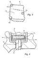
FIGURE 3 is a perspective view illustrating the interior surface of a damper block with projections for engaging the backside of the shroud; and -
FIGURE 4 is an enlarged cross-sectional view illustrating portions of the damper load transfer mechanism and damping mechanism. - Referring now to
Figures 1 and2 , there is illustrated an outer shroud block orbody 10 mounting a plurality ofshrouds 12.Figure 1 is a view in a circumferential direction andFigure 2 is a view in an axial forward direction opposite to the direction of flow of the hot gas stream through the turbine. As seen from a review ofFigure 2 , theshroud block 10 carries preferably threeindividual shrouds 12. It will be appreciated that a plurality ofshroud blocks 10 are disposed in a circumferential array about the turbine axis and mount a plurality ofshrouds 12 surrounding and forming a part of the hot gas path flowing through the turbine. Theshrouds 12 are formed of a ceramic composite, are secured by bolts, not shown, to theshroud blocks 10, and have a first inner surface 11 (Figure 2 ) in contact with the hot gases of the hot gas path. - The damper system of the present invention includes a damper block/shroud interface, a damper load transfer mechanism and a damping mechanism. The damper block/shroud interface includes a
damper block 16 formed of a metallic material, e.g., PM2000, which is a superalloy material having high temperature use limits of up to 1216°C (2200°F). As illustrated inFigures 1 and3 , the radially inwardly facing surface 18 (Figure 3 ) of thedamper block 16 includes at least threeprojections 20 which engage a backside surface 22 (Figure 1 ) of theshroud 12.Projections 20 are sized to distribute sufficient load to theshroud 12, while minimizing susceptibility to wear and binding between theshroud 12 anddamper block 16. The location of theprojections 20 are dependent upon the desired system dynamic response which is determined by system natural frequency vibratory response testing and modal analysis. Consequently, the locations of theprojections 20 are predetermined. - Two of the
projections damper block 16 and adjacent the opposite sides thereof. Consequently, theprojections damper block 16 relative to the sides. Theremaining projection 20c is located adjacent the rear edge of thedamper block 16 and toward one side thereof. Thus, therear projection 20c is located along the rear edge ofblock 16 and asymmetrically relative to the sides of thedamper block 16. It will be appreciated also that with this configuration, theprojections 20 provide a substantial insulating space, i.e., a convective insulating layer, between thedamper block 16 and the backside of theshroud 12, which reduces the heat load on the damper block. Theprojections 20 also compensate for the surface roughness variation commonly associated with ceramic composite shroud surfaces. - The damper load transfer mechanism, generally designated 30, includes a piston assembly having a
piston 32 which passes through anaperture 34 formed in theshroud block 10. The radially inner or distal end of thepiston 32 terminates in aball 36 received within acomplementary socket 38 formed in thedamper block 16 thereby forming a ball-and-socket coupling 39. As best illustrated inFigure 2 , the sides of the piston spaced back from theball 36 are of lesser diameter than the ball andpins 40 are secured, for example, by welding, to thedamper block 16 along opposite sides of the piston to retain the coupling between thedamper block 16 and thepiston 32. The coupling enables relative movement between thepiston 32 andblock 16. - A
central cooling passage 42 is formed axially along the piston, terminating in a pair of film-cooling holes 44 for providing a cooling medium, e.g., compressor discharge air, into the ball-and-socket coupling. The cooling medium, e.g., compressor discharge air, is supplied from a source radially outwardly of thedamper block 10 through the damping mechanism described below. As best illustrated inFigure 4 , the sides of the piston are provided with at least a pair of radially outwardly projecting, axially spacedlands 48. Thelands 48 reduce the potential for the shaft to bind with the aperture of thedamper block 10 due to oxidation and/or wear during long-term continuous operation. - The damper load transfer mechanism also includes superposed metallic and thermally insulated
washers cup 54 carried by thepiston 32. Themetallic washer 50 provides a support for the thermally insulatingwasher 52, which preferably is formed of a monolithic ceramic silicone nitride. The thermallyinsulative washer 52 blocks the conductive heat path of the piston via contact with thedamper block 12. - The damping mechanism includes a
spring 60. The spring is pre-conditioned at temperature and load prior to assembly as a means to ensure consistency in structural compliance. Thespring 60 is mounted within a cup-shaped housing 62 formed along the backside of theshroud block 10. The spring is preloaded to engage at one end theinsulative washer 52 to bias thepiston 32 radially inwardly. The opposite end ofspring 60 engages acap 64 secured, for example, by threads to thehousing 62. Thecap 64 has a central opening orpassage 67 enabling cooling flow from compressor discharge air to flow within the housing to maintain the temperature of the spring below a predetermined temperature. Thus, the spring is made from low-temperature metal alloys to maintain a positive preload on the piston and therefore is kept below a predetermined specific temperature limit. The cooling medium is also supplied to thecooling passage 42 and the film-cooling holes 44 to cool the ball-and-socket coupling. Apassageway 65 is provided to exhaust the spent cooling medium. It will be appreciated that themetallic washer 50 retained by thecup 54 ensures spring retention and preload in the event of a fracture of theinsulative washer 52. - It will be appreciated that in operation, the
spring 60 of the damping mechanism maintains a radial inwardly directed force on thepiston 32 and hence on thedamper block 16. Thedamper block 16, in turn, bears against thebackside surface 22 of theshroud 12 to dampen vibration and particularly to avoid vibratory response at or near resonant frequencies.
Claims (8)
- A damper system for a stage of a turbine comprising:a shroud (12) having a first surface (11) defining in part a hot gas path through the turbine;a shroud body (10) for supporting said shroud (12);a damper block (16) having at least three projections (20) raised from a surface (18) thereof and engaging a backside surface (22) of said shroud (12) opposite said first surface (11); anda damping mechanism (30) carried by said shroud body (10) and connected to said damper block (16) for applying a load to said damper block (16) and said shroud (12) through the engagement of the projections (20) with the backside surface (22) of the shroud (12) thereby damping vibratory movement of said shroud (12);characterized in that the damper block surface (18) is spaced from the backside surface (22) of the shroud by said projections (20) to provide a thermal insulating layer between said shroud (12) and said damper block (16).
- A system according to Claim 1, wherein two of said projections (20a, 20b) lie adjacent a forward edge of said damper block surface (18) in an upstream direction relative to the direction of flow of hot gas through the turbine and a third projection (20c) of said at least three projections lies adjacent a rearward edge of said damper block surface intermediate sides of said damper block.
- A system according to Claim 1 or 2, wherein said shroud is formed of a ceramic material and said damper block is formed of a metallic material.
- A system according to any of claims 1 to 3, wherein said damping mechanism includes a spring (60) and a piston (32) biased by said spring (60) to apply the load to said damper block (16).
- A system according to Claim 4, wherein said damper block (16) is secured to said piston (32) by a ball-and-socket coupling (39) and further comprising at least one cooling passage (42) along said piston (32) for supplying a cooling medium into the ball-and-socket coupling (39).
- A system according to Claim 5, wherein said piston (32) is configured to pass through an aperture (38) in said shroud body (10) and includes at least a pair of lands (48) spaced from one another along a surface of the piston (32) passing through the aperture (38) to minimize binding of the piston (32) and shroud body (10) due to oxidation and/or wear.
- A system according to any of claims 4 to 6, further comprising a housing (62) for said spring (60) in communication with a cooling medium for cooling the spring (62).
- A system according to Claim 7, wherein the housing (62) comprises a cup-shaped housing (62) for the spring (60), the system further comprising a cap (64) at one end of said housing (62) and one end of said spring (60) bearing against said cap (64), an annular thermally insulating washer (52) between an opposite end of the spring (60) and said piston (32), and a cooling passage (67) opening into said housing (62) for cooling the spring (60).
Applications Claiming Priority (2)
| Application Number | Priority Date | Filing Date | Title |
|---|---|---|---|
| US700251 | 2003-11-04 | ||
| US10/700,251 US6942203B2 (en) | 2003-11-04 | 2003-11-04 | Spring mass damper system for turbine shrouds |
Publications (3)
| Publication Number | Publication Date |
|---|---|
| EP1529926A2 EP1529926A2 (en) | 2005-05-11 |
| EP1529926A3 EP1529926A3 (en) | 2012-08-22 |
| EP1529926B1 true EP1529926B1 (en) | 2014-09-17 |
Family
ID=34435517
Family Applications (1)
| Application Number | Title | Priority Date | Filing Date |
|---|---|---|---|
| EP04256829.5A Expired - Lifetime EP1529926B1 (en) | 2003-11-04 | 2004-11-04 | Spring and damper system for turbine shrouds |
Country Status (4)
| Country | Link |
|---|---|
| US (3) | US6942203B2 (en) |
| EP (1) | EP1529926B1 (en) |
| JP (1) | JP4681272B2 (en) |
| CN (1) | CN100430574C (en) |
Families Citing this family (103)
| Publication number | Priority date | Publication date | Assignee | Title |
|---|---|---|---|---|
| JP2005106634A (en) * | 2003-09-30 | 2005-04-21 | Takata Corp | Seat weight measuring apparatus |
| US6942203B2 (en) * | 2003-11-04 | 2005-09-13 | General Electric Company | Spring mass damper system for turbine shrouds |
| US7494317B2 (en) * | 2005-06-23 | 2009-02-24 | Siemens Energy, Inc. | Ring seal attachment system |
| US7278820B2 (en) * | 2005-10-04 | 2007-10-09 | Siemens Power Generation, Inc. | Ring seal system with reduced cooling requirements |
| US7238002B2 (en) * | 2005-11-03 | 2007-07-03 | General Electric Company | Damper seal system and method |
| US20080096819A1 (en) * | 2006-05-02 | 2008-04-24 | Allozyne, Inc. | Amino acid substituted molecules |
| US7665960B2 (en) | 2006-08-10 | 2010-02-23 | United Technologies Corporation | Turbine shroud thermal distortion control |
| US7771160B2 (en) * | 2006-08-10 | 2010-08-10 | United Technologies Corporation | Ceramic shroud assembly |
| US7950234B2 (en) * | 2006-10-13 | 2011-05-31 | Siemens Energy, Inc. | Ceramic matrix composite turbine engine components with unitary stiffening frame |
| US7771159B2 (en) * | 2006-10-16 | 2010-08-10 | General Electric Company | High temperature seals and high temperature sealing systems |
| US7811054B2 (en) * | 2007-05-30 | 2010-10-12 | General Electric Company | Shroud configuration having sloped seal |
| US8047773B2 (en) * | 2007-08-23 | 2011-11-01 | General Electric Company | Gas turbine shroud support apparatus |
| US20090165945A1 (en) * | 2007-12-27 | 2009-07-02 | General Electric Company | Tool for use in the manufacture of turbine bucket shroud and related method |
| US8240988B2 (en) * | 2008-03-26 | 2012-08-14 | Siemens Energy, Inc. | Fastener assembly with cyclone cooling |
| US9127565B2 (en) * | 2008-04-16 | 2015-09-08 | Siemens Energy, Inc. | Apparatus comprising a CMC-comprising body and compliant porous element preloaded within an outer metal shell |
| US8118546B2 (en) * | 2008-08-20 | 2012-02-21 | Siemens Energy, Inc. | Grid ceramic matrix composite structure for gas turbine shroud ring segment |
| US8973375B2 (en) * | 2008-12-31 | 2015-03-10 | Rolls-Royce North American Technologies, Inc. | Shielding for a gas turbine engine component |
| US8382436B2 (en) | 2009-01-06 | 2013-02-26 | General Electric Company | Non-integral turbine blade platforms and systems |
| EP2213841B1 (en) * | 2009-01-28 | 2011-12-14 | Alstom Technology Ltd | Strip seal and method for designing a strip seal |
| US8262345B2 (en) | 2009-02-06 | 2012-09-11 | General Electric Company | Ceramic matrix composite turbine engine |
| WO2010103551A1 (en) * | 2009-03-09 | 2010-09-16 | Avio S.P.A. | Rotor for turbomachines |
| US8393858B2 (en) * | 2009-03-13 | 2013-03-12 | Honeywell International Inc. | Turbine shroud support coupling assembly |
| US8142138B2 (en) | 2009-05-01 | 2012-03-27 | General Electric Company | Turbine engine having cooling pin |
| US20100284810A1 (en) * | 2009-05-07 | 2010-11-11 | General Electric Company | Process for inhibiting delamination in a bend of a continuous fiber-reinforced composite article |
| DE102009039184A1 (en) * | 2009-08-28 | 2011-03-17 | Man Diesel & Turbo Se | turbomachinery |
| US8167546B2 (en) * | 2009-09-01 | 2012-05-01 | United Technologies Corporation | Ceramic turbine shroud support |
| FR2952965B1 (en) * | 2009-11-25 | 2012-03-09 | Snecma | INSULATING A CIRCONFERENTIAL SIDE OF AN EXTERNAL TURBOMACHINE CASTER WITH RESPECT TO A CORRESPONDING RING SECTOR |
| US8529201B2 (en) * | 2009-12-17 | 2013-09-10 | United Technologies Corporation | Blade outer air seal formed of stacked panels |
| JP5569194B2 (en) | 2010-07-02 | 2014-08-13 | 株式会社Ihi | Method for manufacturing shroud segment |
| US8807885B2 (en) * | 2010-10-07 | 2014-08-19 | General Electric Company | Method and apparatus for machining a shroud block |
| US8790067B2 (en) | 2011-04-27 | 2014-07-29 | United Technologies Corporation | Blade clearance control using high-CTE and low-CTE ring members |
| US8864492B2 (en) | 2011-06-23 | 2014-10-21 | United Technologies Corporation | Reverse flow combustor duct attachment |
| US8739547B2 (en) | 2011-06-23 | 2014-06-03 | United Technologies Corporation | Gas turbine engine joint having a metallic member, a CMC member, and a ceramic key |
| US9335051B2 (en) | 2011-07-13 | 2016-05-10 | United Technologies Corporation | Ceramic matrix composite combustor vane ring assembly |
| US8920127B2 (en) | 2011-07-18 | 2014-12-30 | United Technologies Corporation | Turbine rotor non-metallic blade attachment |
| US9328623B2 (en) * | 2011-10-05 | 2016-05-03 | General Electric Company | Turbine system |
| US8920116B2 (en) * | 2011-10-07 | 2014-12-30 | Siemens Energy, Inc. | Wear prevention system for securing compressor airfoils within a turbine engine |
| US9726043B2 (en) | 2011-12-15 | 2017-08-08 | General Electric Company | Mounting apparatus for low-ductility turbine shroud |
| US8899914B2 (en) | 2012-01-05 | 2014-12-02 | United Technologies Corporation | Stator vane integrated attachment liner and spring damper |
| FR2989140B1 (en) * | 2012-04-06 | 2014-09-05 | Snecma | POWER TRANSMISSION SYSTEM FOR A TURBOMACHINE |
| US9527262B2 (en) | 2012-09-28 | 2016-12-27 | General Electric Company | Layered arrangement, hot-gas path component, and process of producing a layered arrangement |
| US9416671B2 (en) | 2012-10-04 | 2016-08-16 | General Electric Company | Bimetallic turbine shroud and method of fabricating |
| US20140223919A1 (en) * | 2013-02-14 | 2014-08-14 | United Technologies Corporation | Flexible liner hanger |
| WO2014158276A2 (en) | 2013-03-05 | 2014-10-02 | Rolls-Royce Corporation | Structure and method for providing compliance and sealing between ceramic and metallic structures |
| WO2014158286A1 (en) | 2013-03-12 | 2014-10-02 | Thomas David J | Turbine blade track assembly |
| US9458726B2 (en) | 2013-03-13 | 2016-10-04 | Rolls-Royce Corporation | Dovetail retention system for blade tracks |
| US9458731B2 (en) | 2013-03-13 | 2016-10-04 | General Electric Company | Turbine shroud cooling system |
| EP2997234B1 (en) | 2013-05-17 | 2020-05-27 | General Electric Company | Cmc shroud support system of a gas turbine |
| CN105518389B (en) | 2013-09-11 | 2017-10-24 | 通用电气公司 | Spring loaded and sealed ceramic matrix composite burner liner |
| JP6529013B2 (en) | 2013-12-12 | 2019-06-12 | ゼネラル・エレクトリック・カンパニイ | CMC shroud support system |
| US9464530B2 (en) * | 2014-02-20 | 2016-10-11 | General Electric Company | Turbine bucket and method for balancing a tip shroud of a turbine bucket |
| US10400619B2 (en) | 2014-06-12 | 2019-09-03 | General Electric Company | Shroud hanger assembly |
| CN106460543B (en) | 2014-06-12 | 2018-12-21 | 通用电气公司 | Multi-piece type shield hangs device assembly |
| EP3155236A1 (en) | 2014-06-12 | 2017-04-19 | General Electric Company | Shroud hanger assembly |
| US10982564B2 (en) | 2014-12-15 | 2021-04-20 | General Electric Company | Apparatus and system for ceramic matrix composite attachment |
| EP3034803A1 (en) | 2014-12-16 | 2016-06-22 | Rolls-Royce Corporation | Hanger system for a turbine engine component |
| US9874104B2 (en) | 2015-02-27 | 2018-01-23 | General Electric Company | Method and system for a ceramic matrix composite shroud hanger assembly |
| US10100649B2 (en) | 2015-03-31 | 2018-10-16 | Rolls-Royce North American Technologies Inc. | Compliant rail hanger |
| FR3036435B1 (en) * | 2015-05-22 | 2020-01-24 | Safran Ceramics | TURBINE RING ASSEMBLY |
| US9963990B2 (en) | 2015-05-26 | 2018-05-08 | Rolls-Royce North American Technologies, Inc. | Ceramic matrix composite seal segment for a gas turbine engine |
| US10370997B2 (en) | 2015-05-26 | 2019-08-06 | Rolls-Royce Corporation | Turbine shroud having ceramic matrix composite seal segment |
| US10087770B2 (en) | 2015-05-26 | 2018-10-02 | Rolls-Royce Corporation | Shroud cartridge having a ceramic matrix composite seal segment |
| US10221713B2 (en) | 2015-05-26 | 2019-03-05 | Rolls-Royce Corporation | Shroud cartridge having a ceramic matrix composite seal segment |
| US10370998B2 (en) | 2015-05-26 | 2019-08-06 | Rolls-Royce Corporation | Flexibly mounted ceramic matrix composite seal segments |
| US10196919B2 (en) | 2015-06-29 | 2019-02-05 | Rolls-Royce North American Technologies Inc. | Turbine shroud segment with load distribution springs |
| US10047624B2 (en) | 2015-06-29 | 2018-08-14 | Rolls-Royce North American Technologies Inc. | Turbine shroud segment with flange-facing perimeter seal |
| US10094234B2 (en) | 2015-06-29 | 2018-10-09 | Rolls-Royce North America Technologies Inc. | Turbine shroud segment with buffer air seal system |
| US10132186B2 (en) * | 2015-08-13 | 2018-11-20 | General Electric Company | System and method for supporting a turbine shroud |
| US9903218B2 (en) * | 2015-08-17 | 2018-02-27 | General Electric Company | Turbine shroud assembly |
| US10443417B2 (en) | 2015-09-18 | 2019-10-15 | General Electric Company | Ceramic matrix composite ring shroud retention methods-finger seals with stepped shroud interface |
| US9945257B2 (en) * | 2015-09-18 | 2018-04-17 | General Electric Company | Ceramic matrix composite ring shroud retention methods-CMC pin-head |
| US10094244B2 (en) | 2015-09-18 | 2018-10-09 | General Electric Company | Ceramic matrix composite ring shroud retention methods-wiggle strip spring seal |
| US10138750B2 (en) | 2016-03-16 | 2018-11-27 | United Technologies Corporation | Boas segmented heat shield |
| DE102016211613A1 (en) * | 2016-06-28 | 2017-12-28 | Siemens Aktiengesellschaft | Heat shield arrangement of a combustion chamber with disc spring package |
| FR3056636B1 (en) * | 2016-09-27 | 2020-06-05 | Safran Aircraft Engines | TURBINE RING ASSEMBLY WITHOUT COLD MOUNTING SET |
| US10533581B2 (en) | 2016-12-09 | 2020-01-14 | United Technologies Corporation | Stator with support structure feature for tuned airfoil |
| US10371611B2 (en) | 2017-01-12 | 2019-08-06 | Rolls-Royce North American Technologies Inc. | Material testing system and method of use |
| US10480337B2 (en) | 2017-04-18 | 2019-11-19 | Rolls-Royce North American Technologies Inc. | Turbine shroud assembly with multi-piece seals |
| US10544701B2 (en) * | 2017-06-15 | 2020-01-28 | General Electric Company | Turbine shroud assembly |
| US10526921B2 (en) | 2017-06-15 | 2020-01-07 | General Electric Company | Anti-rotation shroud dampening pin and turbine shroud assembly |
| US10669895B2 (en) | 2017-06-15 | 2020-06-02 | General Electric Company | Shroud dampening pin and turbine shroud assembly |
| US10876417B2 (en) | 2017-08-17 | 2020-12-29 | Raytheon Technologies Corporation | Tuned airfoil assembly |
| US10557365B2 (en) | 2017-10-05 | 2020-02-11 | Rolls-Royce Corporation | Ceramic matrix composite blade track with mounting system having reaction load distribution features |
| US10392957B2 (en) | 2017-10-05 | 2019-08-27 | Rolls-Royce Corporation | Ceramic matrix composite blade track with mounting system having load distribution features |
| US10619514B2 (en) | 2017-10-18 | 2020-04-14 | Rolls-Royce Corporation | Ceramic matrix composite assembly with compliant pin attachment features |
| CN107882599B (en) * | 2017-11-01 | 2021-02-09 | 中国航发湖南动力机械研究所 | Integral turbine outer ring connecting structure and turbine engine |
| US11021986B2 (en) | 2018-03-20 | 2021-06-01 | Raytheon Technologies Corporation | Seal assembly for gas turbine engine |
| US10711630B2 (en) | 2018-03-20 | 2020-07-14 | Honeywell International Inc. | Retention and control system for turbine shroud ring |
| US10689997B2 (en) | 2018-04-17 | 2020-06-23 | Raytheon Technologies Corporation | Seal assembly for gas turbine engine |
| US10801351B2 (en) | 2018-04-17 | 2020-10-13 | Raytheon Technologies Corporation | Seal assembly for gas turbine engine |
| US11047250B2 (en) * | 2019-04-05 | 2021-06-29 | Raytheon Technologies Corporation | CMC BOAS transverse hook arrangement |
| US11536454B2 (en) * | 2019-05-09 | 2022-12-27 | Pratt & Whitney Canada Corp. | Combustor wall assembly for gas turbine engine |
| US11174739B2 (en) | 2019-08-27 | 2021-11-16 | Solar Turbines Incorporated | Damped turbine blade assembly |
| US11359507B2 (en) | 2019-09-26 | 2022-06-14 | Raytheon Technologies Corporation | Double box composite seal assembly with fiber density arrangement for gas turbine engine |
| US11220924B2 (en) | 2019-09-26 | 2022-01-11 | Raytheon Technologies Corporation | Double box composite seal assembly with insert for gas turbine engine |
| US11352897B2 (en) | 2019-09-26 | 2022-06-07 | Raytheon Technologies Corporation | Double box composite seal assembly for gas turbine engine |
| US11149563B2 (en) | 2019-10-04 | 2021-10-19 | Rolls-Royce Corporation | Ceramic matrix composite blade track with mounting system having axial reaction load distribution features |
| US11041399B2 (en) * | 2019-11-01 | 2021-06-22 | Raytheon Technologies Corporation | CMC heat shield |
| US11187098B2 (en) | 2019-12-20 | 2021-11-30 | Rolls-Royce Corporation | Turbine shroud assembly with hangers for ceramic matrix composite material seal segments |
| CN115315329B (en) * | 2020-03-31 | 2024-10-29 | Maq股份公司 | Tool holder for a tool assembly and tool assembly including the tool holder |
| US12055058B2 (en) * | 2022-05-31 | 2024-08-06 | Pratt & Whitney Canada Corp. | Joint between gas turbine engine components with a spring element |
| CN115013079B (en) * | 2022-07-08 | 2024-10-29 | 泰安凯顺机电工程有限公司 | A steam turbine |
| US12091980B1 (en) | 2023-12-13 | 2024-09-17 | Honeywell International Inc. | Spring biased shroud retention system for gas turbine engine |
Family Cites Families (25)
| Publication number | Priority date | Publication date | Assignee | Title |
|---|---|---|---|---|
| US3864056A (en) * | 1973-07-27 | 1975-02-04 | Westinghouse Electric Corp | Cooled turbine blade ring assembly |
| US4087199A (en) * | 1976-11-22 | 1978-05-02 | General Electric Company | Ceramic turbine shroud assembly |
| US4245954A (en) * | 1978-12-01 | 1981-01-20 | Westinghouse Electric Corp. | Ceramic turbine stator vane and shroud support |
| CA1156844A (en) * | 1980-08-27 | 1983-11-15 | Westinghouse Canada Inc. | Blade tip clearance control for an industrial gas turbine engine |
| US4621976A (en) * | 1985-04-23 | 1986-11-11 | United Technologies Corporation | Integrally cast vane and shroud stator with damper |
| FR2597921A1 (en) * | 1986-04-24 | 1987-10-30 | Snecma | SECTORIZED TURBINE RING |
| US5346362A (en) * | 1993-04-26 | 1994-09-13 | United Technologies Corporation | Mechanical damper |
| DE4329014C1 (en) * | 1993-08-28 | 1995-01-05 | Mtu Muenchen Gmbh | Rotor housing, especially housing for turbine engines |
| US5618161A (en) * | 1995-10-17 | 1997-04-08 | Westinghouse Electric Corporation | Apparatus for restraining motion of a turbo-machine stationary vane |
| US5639211A (en) * | 1995-11-30 | 1997-06-17 | United Technology Corporation | Brush seal for stator of a gas turbine engine case |
| US6024898A (en) * | 1996-12-30 | 2000-02-15 | General Electric Company | Article and method for making complex shaped preform and silicon carbide composite by melt infiltration |
| US5952100A (en) * | 1997-05-21 | 1999-09-14 | General Electric Company | Silicon-doped boron nitride coated fibers in silicon melt infiltrated composites |
| DE19740990C2 (en) * | 1997-09-18 | 2001-11-29 | Enidine Gmbh | Piston-cylinder arrangement |
| FR2780443B1 (en) * | 1998-06-25 | 2000-08-04 | Snecma | HIGH PRESSURE TURBINE STATOR RING OF A TURBOMACHINE |
| US6126389A (en) * | 1998-09-02 | 2000-10-03 | General Electric Co. | Impingement cooling for the shroud of a gas turbine |
| US6315519B1 (en) * | 1998-09-28 | 2001-11-13 | General Electric Company | Turbine inner shroud and turbine assembly containing such inner shroud |
| US6113349A (en) * | 1998-09-28 | 2000-09-05 | General Electric Company | Turbine assembly containing an inner shroud |
| US6092984A (en) * | 1998-12-18 | 2000-07-25 | General Electric Company | System life for continuously operating engines |
| US6403158B1 (en) * | 1999-03-05 | 2002-06-11 | General Electric Company | Porous body infiltrating method |
| US6435824B1 (en) * | 2000-11-08 | 2002-08-20 | General Electric Co. | Gas turbine stationary shroud made of a ceramic foam material, and its preparation |
| US6503441B2 (en) * | 2001-05-30 | 2003-01-07 | General Electric Company | Method for producing melt-infiltrated ceramic composites using formed supports |
| US6726448B2 (en) * | 2002-05-15 | 2004-04-27 | General Electric Company | Ceramic turbine shroud |
| JP2004036443A (en) * | 2002-07-02 | 2004-02-05 | Ishikawajima Harima Heavy Ind Co Ltd | Gas turbine shroud structure |
| US6814538B2 (en) * | 2003-01-22 | 2004-11-09 | General Electric Company | Turbine stage one shroud configuration and method for service enhancement |
| US6942203B2 (en) * | 2003-11-04 | 2005-09-13 | General Electric Company | Spring mass damper system for turbine shrouds |
-
2003
- 2003-11-04 US US10/700,251 patent/US6942203B2/en not_active Expired - Lifetime
-
2004
- 2004-03-05 US US10/793,051 patent/US7117983B2/en not_active Expired - Lifetime
- 2004-11-04 JP JP2004320157A patent/JP4681272B2/en not_active Expired - Lifetime
- 2004-11-04 CN CNB2004100903739A patent/CN100430574C/en not_active Expired - Lifetime
- 2004-11-04 EP EP04256829.5A patent/EP1529926B1/en not_active Expired - Lifetime
-
2006
- 2006-08-16 US US11/504,673 patent/US7434670B2/en not_active Expired - Lifetime
Also Published As
| Publication number | Publication date |
|---|---|
| US20080202877A1 (en) | 2008-08-28 |
| JP4681272B2 (en) | 2011-05-11 |
| CN1614199A (en) | 2005-05-11 |
| US20050092566A1 (en) | 2005-05-05 |
| US20050093214A1 (en) | 2005-05-05 |
| EP1529926A2 (en) | 2005-05-11 |
| CN100430574C (en) | 2008-11-05 |
| US7434670B2 (en) | 2008-10-14 |
| US6942203B2 (en) | 2005-09-13 |
| JP2005140114A (en) | 2005-06-02 |
| EP1529926A3 (en) | 2012-08-22 |
| US7117983B2 (en) | 2006-10-10 |
Similar Documents
| Publication | Publication Date | Title |
|---|---|---|
| US6942203B2 (en) | Spring mass damper system for turbine shrouds | |
| US7238002B2 (en) | Damper seal system and method | |
| CN107882599B (en) | Integral turbine outer ring connecting structure and turbine engine | |
| KR100405881B1 (en) | Shroud for rotor assembly, shroud for gas turbine rotor assembly and suspension apparatus | |
| JP5435910B2 (en) | Gas turbine shroud support device | |
| JP3701680B2 (en) | Vibration damping shroud for turbomachine blades | |
| US5333995A (en) | Wear shim for a turbine engine | |
| CA2729528C (en) | Mounting apparatus for low-ductility turbine shroud | |
| EP2154335B1 (en) | Ring seal attachment system | |
| US7040857B2 (en) | Flexible seal assembly between gas turbine components and methods of installation | |
| US7866162B2 (en) | Exhaust cone for channeling a stream of gas downstream from a turbine | |
| JP5988976B2 (en) | Method for mounting a shield on a turbine casing and mounting assembly for performing this method | |
| CN111853855B (en) | Gas turbine engine combustor | |
| US20190136980A1 (en) | Ceramic seal runner and mount for a rotating shaft | |
| US6000906A (en) | Ceramic airfoil | |
| CN102046926B (en) | High pressure turbine for turbine engine with improved assembly of moving blade radial clearance control box | |
| JP2012154613A (en) | Support body between transition piece and impingement sleeve in combustor | |
| US20190226357A1 (en) | Cooling device for a turbine of a turbomachine | |
| US20200063581A1 (en) | Cmc airfoil assembly | |
| US11435078B2 (en) | Stand-off device for double-skin combustor liner | |
| CN117627731A (en) | Rotor blade assemblies for turbine engines | |
| JP2004245294A (en) | Foil type hydrodynamic bearing device | |
| JPH0295733A (en) | gas turbine combustion equipment | |
| RU2377162C1 (en) | Device to suspend gas turbine engine to aircraft | |
| JPS5910710A (en) | Turbocharger |
Legal Events
| Date | Code | Title | Description |
|---|---|---|---|
| PUAI | Public reference made under article 153(3) epc to a published international application that has entered the european phase |
Free format text: ORIGINAL CODE: 0009012 |
|
| AK | Designated contracting states |
Kind code of ref document: A2 Designated state(s): AT BE BG CH CY CZ DE DK EE ES FI FR GB GR HU IE IS IT LI LU MC NL PL PT RO SE SI SK TR |
|
| AX | Request for extension of the european patent |
Extension state: AL HR LT LV MK YU |
|
| PUAL | Search report despatched |
Free format text: ORIGINAL CODE: 0009013 |
|
| AK | Designated contracting states |
Kind code of ref document: A3 Designated state(s): AT BE BG CH CY CZ DE DK EE ES FI FR GB GR HU IE IS IT LI LU MC NL PL PT RO SE SI SK TR |
|
| AX | Request for extension of the european patent |
Extension state: AL HR LT LV MK YU |
|
| RIC1 | Information provided on ipc code assigned before grant |
Ipc: F01D 11/08 20060101ALI20120713BHEP Ipc: F01D 25/24 20060101ALI20120713BHEP Ipc: F01D 25/04 20060101AFI20120713BHEP Ipc: F01D 9/04 20060101ALI20120713BHEP Ipc: F01D 25/00 20060101ALI20120713BHEP |
|
| 17P | Request for examination filed |
Effective date: 20130222 |
|
| 17Q | First examination report despatched |
Effective date: 20130325 |
|
| AKX | Designation fees paid |
Designated state(s): CH DE FR LI |
|
| GRAP | Despatch of communication of intention to grant a patent |
Free format text: ORIGINAL CODE: EPIDOSNIGR1 |
|
| INTG | Intention to grant announced |
Effective date: 20140530 |
|
| GRAS | Grant fee paid |
Free format text: ORIGINAL CODE: EPIDOSNIGR3 |
|
| GRAA | (expected) grant |
Free format text: ORIGINAL CODE: 0009210 |
|
| AK | Designated contracting states |
Kind code of ref document: B1 Designated state(s): CH DE FR LI |
|
| REG | Reference to a national code |
Ref country code: CH Ref legal event code: EP |
|
| REG | Reference to a national code |
Ref country code: DE Ref legal event code: R096 Ref document number: 602004045840 Country of ref document: DE Effective date: 20141030 |
|
| REG | Reference to a national code |
Ref country code: DE Ref legal event code: R097 Ref document number: 602004045840 Country of ref document: DE |
|
| PLBE | No opposition filed within time limit |
Free format text: ORIGINAL CODE: 0009261 |
|
| STAA | Information on the status of an ep patent application or granted ep patent |
Free format text: STATUS: NO OPPOSITION FILED WITHIN TIME LIMIT |
|
| 26N | No opposition filed |
Effective date: 20150618 |
|
| REG | Reference to a national code |
Ref country code: FR Ref legal event code: PLFP Year of fee payment: 12 |
|
| REG | Reference to a national code |
Ref country code: FR Ref legal event code: PLFP Year of fee payment: 13 |
|
| REG | Reference to a national code |
Ref country code: FR Ref legal event code: PLFP Year of fee payment: 14 |
|
| REG | Reference to a national code |
Ref country code: FR Ref legal event code: PLFP Year of fee payment: 15 |
|
| PGFP | Annual fee paid to national office [announced via postgrant information from national office to epo] |
Ref country code: CH Payment date: 20201022 Year of fee payment: 17 Ref country code: FR Payment date: 20201021 Year of fee payment: 17 |
|
| REG | Reference to a national code |
Ref country code: CH Ref legal event code: PL |
|
| PG25 | Lapsed in a contracting state [announced via postgrant information from national office to epo] |
Ref country code: FR Free format text: LAPSE BECAUSE OF NON-PAYMENT OF DUE FEES Effective date: 20211130 |
|
| PG25 | Lapsed in a contracting state [announced via postgrant information from national office to epo] |
Ref country code: LI Free format text: LAPSE BECAUSE OF NON-PAYMENT OF DUE FEES Effective date: 20220701 Ref country code: CH Free format text: LAPSE BECAUSE OF NON-PAYMENT OF DUE FEES Effective date: 20220701 |
|
| REG | Reference to a national code |
Ref country code: DE Ref legal event code: R081 Ref document number: 602004045840 Country of ref document: DE Owner name: GENERAL ELECTRIC TECHNOLOGY GMBH, CH Free format text: FORMER OWNER: GENERAL ELECTRIC COMPANY, SCHENECTADY, N.Y., US |
|
| PGFP | Annual fee paid to national office [announced via postgrant information from national office to epo] |
Ref country code: DE Payment date: 20231019 Year of fee payment: 20 |
|
| REG | Reference to a national code |
Ref country code: DE Ref legal event code: R071 Ref document number: 602004045840 Country of ref document: DE |