EP1529658A1 - Pneumatic tire - Google Patents
Pneumatic tire Download PDFInfo
- Publication number
- EP1529658A1 EP1529658A1 EP04025999A EP04025999A EP1529658A1 EP 1529658 A1 EP1529658 A1 EP 1529658A1 EP 04025999 A EP04025999 A EP 04025999A EP 04025999 A EP04025999 A EP 04025999A EP 1529658 A1 EP1529658 A1 EP 1529658A1
- Authority
- EP
- European Patent Office
- Prior art keywords
- ground contact
- contact length
- main grooves
- tire
- shoulder
- Prior art date
- Legal status (The legal status is an assumption and is not a legal conclusion. Google has not performed a legal analysis and makes no representation as to the accuracy of the status listed.)
- Granted
Links
- 230000001788 irregular Effects 0.000 description 6
- 230000000052 comparative effect Effects 0.000 description 4
- 238000011156 evaluation Methods 0.000 description 3
- 230000001629 suppression Effects 0.000 description 2
- 230000015572 biosynthetic process Effects 0.000 description 1
- 230000000694 effects Effects 0.000 description 1
- 238000010998 test method Methods 0.000 description 1
Images


Classifications
-
- B—PERFORMING OPERATIONS; TRANSPORTING
- B60—VEHICLES IN GENERAL
- B60C—VEHICLE TYRES; TYRE INFLATION; TYRE CHANGING; CONNECTING VALVES TO INFLATABLE ELASTIC BODIES IN GENERAL; DEVICES OR ARRANGEMENTS RELATED TO TYRES
- B60C11/00—Tyre tread bands; Tread patterns; Anti-skid inserts
- B60C11/0083—Tyre tread bands; Tread patterns; Anti-skid inserts characterised by the curvature of the tyre tread
-
- B—PERFORMING OPERATIONS; TRANSPORTING
- B60—VEHICLES IN GENERAL
- B60C—VEHICLE TYRES; TYRE INFLATION; TYRE CHANGING; CONNECTING VALVES TO INFLATABLE ELASTIC BODIES IN GENERAL; DEVICES OR ARRANGEMENTS RELATED TO TYRES
- B60C11/00—Tyre tread bands; Tread patterns; Anti-skid inserts
- B60C11/03—Tread patterns
- B60C11/0327—Tread patterns characterised by special properties of the tread pattern
- B60C11/0332—Tread patterns characterised by special properties of the tread pattern by the footprint-ground contacting area of the tyre tread
-
- B—PERFORMING OPERATIONS; TRANSPORTING
- B60—VEHICLES IN GENERAL
- B60C—VEHICLE TYRES; TYRE INFLATION; TYRE CHANGING; CONNECTING VALVES TO INFLATABLE ELASTIC BODIES IN GENERAL; DEVICES OR ARRANGEMENTS RELATED TO TYRES
- B60C11/00—Tyre tread bands; Tread patterns; Anti-skid inserts
- B60C11/03—Tread patterns
- B60C11/04—Tread patterns in which the raised area of the pattern consists only of continuous circumferential ribs, e.g. zig-zag
-
- B—PERFORMING OPERATIONS; TRANSPORTING
- B60—VEHICLES IN GENERAL
- B60C—VEHICLE TYRES; TYRE INFLATION; TYRE CHANGING; CONNECTING VALVES TO INFLATABLE ELASTIC BODIES IN GENERAL; DEVICES OR ARRANGEMENTS RELATED TO TYRES
- B60C11/00—Tyre tread bands; Tread patterns; Anti-skid inserts
- B60C11/03—Tread patterns
- B60C11/04—Tread patterns in which the raised area of the pattern consists only of continuous circumferential ribs, e.g. zig-zag
- B60C11/042—Tread patterns in which the raised area of the pattern consists only of continuous circumferential ribs, e.g. zig-zag further characterised by the groove cross-section
Definitions
- the present invention relates to pneumatic tires, and more particularly, to a pneumatic tire which can improve irregular wear.
- pneumatic tires used for vehicles such as buses and trucks employ a rib pattern having ribs defined by main grooves extending in a circumferential direction of the tire in a tread surface thereof.
- These pneumatic tires have a problem of irregular wear such as shoulder wear that the outer edge portions of ribs located in the opposite shoulder regions of the tread surface wear earlier, and railway wear that wear grows along the edge portions on one side of the ribs, especially the inner edge portions of the ribs located in the shoulder regions.
- the growth of such irregular wear develops polygonal wear, which encourages vibration of the tire.
- a pneumatic tire is disclosed in Unexamined Japanese Patent Application Publication No. 8-85308, which includes ribs having a specified ground contact length to thereby improve irregular wear.
- the pneumatic tire to be particularly mounted on a steering wheel does not have a sufficient effect of preventing railway wear and shoulder wear, and further improvement is desired.
- An obj ect of the present invention is to provide a pneumatic tire in which both railway wear and shoulder wear can effectively be suppressed.
- a pneumatic tire according to the present invention includes a tread surface having four main grooves extending in a circumferential direction of the tire, the four main grooves consisting of two inner main grooves disposed on both sides of an equatorial plane of the tire and two outer main grooves disposed outwardly of the two inner main grooves, three land portions extending in the tire circumferential direction being formed in a center region located between the two outer main grooves, a land portion extending in the tire circumferential direction being formed in each of shoulder regions located outwardly of the two outer main grooves, wherein the following relationships are fulfilled when the tread surface contacts with a ground: 0.80 ⁇ B/A ⁇ 0.95 0.90 ⁇ C/B ⁇ 1.00 where A is the ground contact length of the central land portion of the three land portions in the center region, B is the ground contact length of the outer edge of the land portion in the shoulder region and C is the ground contact length of the inner edge of the land portion in the shoulder region.
- the ground contact length A of the center land portion in the center region, and the ground contact length B of the outer edge and the ground contact length C of the inner edge of the land portion in the shoulder region have relationships specified as described above to thereby make the ground contact shape of the tread surface optimal for suppression of shoulder wear and railway wear created on the ribs in the shoulder regions, which allows for effective suppression of occurrence of the two wears. Therefore, railway wear resistance as well as shoulder wear resistance can be enhanced.
- a tread surface 1 has four main grooves 2 extending straight along a circumferential direction T of the tire.
- the four main grooves 2 include two inner main grooves 2B placed on both sides of an equatorial plane CL of the tire, and two outer main grooves 2A placed outwardly of the two inner main grooves 2B, and are symmetrically located with respect to the tire equatorial plane CL.
- These four main grooves 2 defines five ribs (land portions) 3 extending in the tire circumferential direction T in the tread surface 1.
- Three ribs 3A are disposed in a center region 1A of the tread surface 1 located between the two outer main grooves 2A.
- the central rib 3A1 thereof is disposed on the tire equatorial plane CL, and the ribs 3A2 on both sides of the central rib are symmetrically placed with respect to the tire equatorial plane CL.
- One rib 3B is provided in each of two shoulder regions 1B located outwardly of the two outer main grooves 2A.
- the central rib 3A1 in the center region 1A and the ribs 3A in the shoulder regions 1B satisfy the following relationships: 0.80 ⁇ B/A ⁇ 0.95 0.90 ⁇ C/B ⁇ 1.00 where A is the ground contact length in millimeters of the central rib 3A1 on the tire equatorial plane CL, B is the ground contact length in millimeters of the outer edge b of the rib 3B and C is the ground contact length in millimeters of the inner edge c of the rib 3B
- the ground contact length D in millimeters of the outer edge d of each of the ribs 3A2 on both sides in the center region 1A is equal to or shorter than the ground contact length E in millimeters of the inner edge e thereof.
- the ground contact length E of the inner edge e is equal to or shorter than the ground contact length A of the central rib 3A1, and is equal to or longer than the ground contact length B of the outer edge b of the rib 3B in the shoulder region 1B.
- the ground contact length D of the outer edge d of the rib 3A2 is equal to or longer than the ground contact length C of the inner edge c of the rib 3B.
- ground contact length of the rib is the ground contact length of the rib measured when a tire contacts with a ground (road surface) under conditions such that the tire is mounted on a standard rim described in JATMA (JATMA YEAR BOOK 2003) and an air pressure and a load corresponding to the maximum load ability described therein are applied thereto.
- ground contact shape can be obtained, for example, by making the curvature radius of the center region 1A of the tread surface 1 properly greater than that of the shoulder region 1B, or by properly adjusting the groove wall angles of the main grooves 2.
- the present inventor has found the following fact through an intense study about railway wear and shoulder wear which were problematic with heavy duty pneumatic tires to be mounted on a steering wheel, having a tread surface with the four main grooves.
- the relationships between the ground contact lengths of the ribs 3 defined by the four main grooves 2 are specified as described above. Formation of the ground contact shape having the relationships, specified as mentioned above, between the ground contact length A of the central rib 3A1 located on the tire equatorial plane CL in the center region 1A, and the ground contact lengths B and C of each of the ribs 3B located in the shoulder regions 1B, allows the ground contact shape of the tread surface 1 to be optimized for restriction of shoulder wear and railway wear created on the ribs 3B in the shoulder regions 1B to thereby effectively suppress occurrence of the two wears. Accordingly, railway wear as well as shoulder wear can be improved.
- ratio B/A is less than 0.80, it is not preferable because the central rib 3A1 is susceptible to occurrence of irregular wear called rib punch. If the ratio B/A is greater than 0. 95, it is difficult to effectively suppress shoulder wear.
- ground contact lengths D and E of each of the ribs 3A2 onboth sides in the center region 1A are specified as described above, railway wear created along the outer edge d of each of the ribs 3A2 can effectively be suppressed without creating a problem of other irregular wear.
- the present invention is preferably applicable to heavy duty pneumatic tires to be mounted on a steering wheel, but is not limited thereto.
- tires 1 to 5 Prepared, respectively, were tires 1 to 5 according to the present invention, comparative tires 1 and 2 and a conventional tire having a tire size of 295/75R22.5 and an arrangement shown in FIG. 1, each tire except the conventional tire having the ratio B/A of the ground contact length B of the outer edge of the rib in the shoulder region to the ground contact length A of the central rib in the center region, and the ratio C/B of the ground contact length C of the inner edge of the rib in the shoulder region to the ground contact length B of the outer edge thereof shown in Table 1, the conventional tire having ribs having the same ground contact length.
- the ground contact length D of the outer edge of each of the ribs on both sides in the center region, and the ground contact length E of the inner edge thereof had the following relationships: D ⁇ E E ⁇ A E>B D>C
- test tire was mounted on a 8.25 ⁇ 22.5 sized rim, an air pressure of 760 kPa was applied thereto, and the resulting tire was attached to a truck with a load of 20 tons as a front wheel. Evaluation tests for shoulder wear and railway wear were conducted in accordance with the following test methods. The results shown in Table 1 were obtained.
- the wear amount of the central rib in the center region of each teat tire and the wear amount of the outer edge of each of the ribs in the shoulder regions thereof were measured after traveling of 60, 000 miles (96, 000 km) along a public road, and shoulder wear of each test tire was evaluated from the difference between the two wear amounts.
- the evaluation results of the test tires were represented by the index on the basis of the conventional tire as 100. The greater the index value is, the less the shoulder wear occurs and the better the shoulder wear resistance is.
- the tires according to the present invention can effectively suppress shoulder wear and railway wear, and improve shoulder wear resistance as well as railway wear resistance.
Landscapes
- Engineering & Computer Science (AREA)
- Mechanical Engineering (AREA)
- Tires In General (AREA)
Abstract
Description
- The present invention relates to pneumatic tires, and more particularly, to a pneumatic tire which can improve irregular wear.
- In general, pneumatic tires used for vehicles such as buses and trucks employ a rib pattern having ribs defined by main grooves extending in a circumferential direction of the tire in a tread surface thereof. These pneumatic tires have a problem of irregular wear such as shoulder wear that the outer edge portions of ribs located in the opposite shoulder regions of the tread surface wear earlier, and railway wear that wear grows along the edge portions on one side of the ribs, especially the inner edge portions of the ribs located in the shoulder regions. The growth of such irregular wear develops polygonal wear, which encourages vibration of the tire.
- Conventionally, to solve the above problem, a pneumatic tire is disclosed in Unexamined Japanese Patent Application Publication No. 8-85308, which includes ribs having a specified ground contact length to thereby improve irregular wear.
- However, the pneumatic tire to be particularly mounted on a steering wheel does not have a sufficient effect of preventing railway wear and shoulder wear, and further improvement is desired.
- An obj ect of the present invention is to provide a pneumatic tire in which both railway wear and shoulder wear can effectively be suppressed.
- In order to achieve the above object, a pneumatic tire according to the present invention includes a tread surface having four main grooves extending in a circumferential direction of the tire, the four main grooves consisting of two inner main grooves disposed on both sides of an equatorial plane of the tire and two outer main grooves disposed outwardly of the two inner main grooves, three land portions extending in the tire circumferential direction being formed in a center region located between the two outer main grooves, a land portion extending in the tire circumferential direction being formed in each of shoulder regions located outwardly of the two outer main grooves, wherein the following relationships are fulfilled when the tread surface contacts with a ground:
- According to the present invention described above, the ground contact length A of the center land portion in the center region, and the ground contact length B of the outer edge and the ground contact length C of the inner edge of the land portion in the shoulder region have relationships specified as described above to thereby make the ground contact shape of the tread surface optimal for suppression of shoulder wear and railway wear created on the ribs in the shoulder regions, which allows for effective suppression of occurrence of the two wears. Therefore, railway wear resistance as well as shoulder wear resistance can be enhanced.
-
- FIG. 1 is a partial development view of a tread surface showing an embodiment of a pneumatic tire according to the present invention;
- FIG. 2 is a view for schematically illustrating a ground contact shape of the tread surface of the pneumatic tire of the present invention;
- FIG. 3 is a view for schematically illustrating a ground contact shape of a tread surface of the case where ribs in the shoulder regions have ground contact lengths longer than those in the center side;
- FIG. 4 is a view for schematically illustrating a ground contact shape of a tread surface of the case where ribs in the shoulder regions have ground contact lengths shorter than those in the center side;
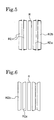
- FIG. 5 is a view for schematically illustrating a ground contact shape of a tread surface of the case where the ground contact length of the inner edge of each rib in the shoulder region is longer than that of the outer edge thereof, and where the ground contact length of the outer edge of each of ribs on both sides in the center region is longer than that of the inner edge thereof; and
- FIG. 6 is a view for schematically illustrating a ground contact shape of a tread surface of the case where the ground contact length of the inner edge of each rib in the shoulder region is shorter than that of the outer edge thereof, and where the ground contact length of the outer edge of each of ribs on both sides in the center region is shorter than that of the inner edge thereof.
-
- The embodiment of the present invention will be described in detail below with reference to the drawings.
- Referring to Fig. 1, there is shown an embodiment of a pneumatic tire according to the present invention. A tread surface 1 has four
main grooves 2 extending straight along a circumferential direction T of the tire. The fourmain grooves 2 include two innermain grooves 2B placed on both sides of an equatorial plane CL of the tire, and two outermain grooves 2A placed outwardly of the two innermain grooves 2B, and are symmetrically located with respect to the tire equatorial plane CL. These fourmain grooves 2 defines five ribs (land portions) 3 extending in the tire circumferential direction T in the tread surface 1. - Three
ribs 3A are disposed in acenter region 1A of the tread surface 1 located between the two outermain grooves 2A. The central rib 3A1 thereof is disposed on the tire equatorial plane CL, and the ribs 3A2 on both sides of the central rib are symmetrically placed with respect to the tire equatorial plane CL. Onerib 3B is provided in each of twoshoulder regions 1B located outwardly of the two outermain grooves 2A. - As shown in FIG. 2, when the tread surface 1 engages a road surface, the central rib 3A1 in the
center region 1A and theribs 3A in theshoulder regions 1B satisfy the following relationships:rib 3B and C is the ground contact length in millimeters of the inner edge c of therib 3B - The ground contact length D in millimeters of the outer edge d of each of the ribs 3A2 on both sides in the
center region 1A is equal to or shorter than the ground contact length E in millimeters of the inner edge e thereof. The ground contact length E of the inner edge e is equal to or shorter than the ground contact length A of the central rib 3A1, and is equal to or longer than the ground contact length B of the outer edge b of therib 3B in theshoulder region 1B. The ground contact length D of the outer edge d of the rib 3A2 is equal to or longer than the ground contact length C of the inner edge c of therib 3B. - The term "ground contact length of the rib" as used herein is the ground contact length of the rib measured when a tire contacts with a ground (road surface) under conditions such that the tire is mounted on a standard rim described in JATMA (JATMA YEAR BOOK 2003) and an air pressure and a load corresponding to the maximum load ability described therein are applied thereto.
- The aforementioned ground contact shape (footprint) can be obtained, for example, by making the curvature radius of the
center region 1A of the tread surface 1 properly greater than that of theshoulder region 1B, or by properly adjusting the groove wall angles of themain grooves 2. - The present inventor has found the following fact through an intense study about railway wear and shoulder wear which were problematic with heavy duty pneumatic tires to be mounted on a steering wheel, having a tread surface with the four main grooves.
- It turned out that, as shown in FIG. 3, when the ground contact shape of a tread surface having five ribs R defined by the four main grooves was formed such that ribs R1 in the shoulder regions had ground contact lengths longer than those of the ribs in the center side, a high tendency to create shoulder wear was shown, and that, as shown in FIG. 4, when the ground contact shape of the tread surface was formed such that ribs R1 in the shoulder regions had ground contact lengths shorter than those of the ribs in the center side, a low tendency to create shoulder wear was shown.
- Also, it turned out that, as shown in FIG. 5, when the ground contact length of the inner edge of a rib R2b in the shoulder region was longer than the ground contact length of the outer edge thereof, railway wear occurred in a shaded section of the rib R2b, and when the ground contact length of the outer edge of a rib R2a in the center region was longer than the ground contact length of the inner edge thereof, railway wear occurred in a shaded section of the rib R2a.
- Further, it turned out that, as shown in FIG. 6, when the ground contact length of the inner edge of a rib R2b in the shoulder region was shorter than the ground contact length of the outer edge thereof, the rib R2b had a low tendency to create railway wear, and when the ground contact length of the outer edge of a rib R2a in the center region was shorter than the ground contact length of the inner edge thereof, the rib R2a had a low tendency to create railway wear.
- Therefore, in the present invention, the relationships between the ground contact lengths of the
ribs 3 defined by the fourmain grooves 2 are specified as described above. Formation of the ground contact shape having the relationships, specified as mentioned above, between the ground contact length A of the central rib 3A1 located on the tire equatorial plane CL in thecenter region 1A, and the ground contact lengths B and C of each of theribs 3B located in theshoulder regions 1B, allows the ground contact shape of the tread surface 1 to be optimized for restriction of shoulder wear and railway wear created on theribs 3B in theshoulder regions 1B to thereby effectively suppress occurrence of the two wears. Accordingly, railway wear as well as shoulder wear can be improved. - If the ratio B/A is less than 0.80, it is not preferable because the central rib 3A1 is susceptible to occurrence of irregular wear called rib punch. If the ratio B/A is greater than 0. 95, it is difficult to effectively suppress shoulder wear.
- If the ratio C/B is less than 0. 9, or is greater than 1. 00, railway wear can not effectively be suppressed.
- The ground contact lengths D and E of each of the ribs 3A2 onboth sides in the
center region 1A are specified as described above, railway wear created along the outer edge d of each of the ribs 3A2 can effectively be suppressed without creating a problem of other irregular wear. - In particular, the present invention is preferably applicable to heavy duty pneumatic tires to be mounted on a steering wheel, but is not limited thereto.
- Prepared, respectively, were tires 1 to 5 according to the present invention,
comparative tires 1 and 2 and a conventional tire having a tire size of 295/75R22.5 and an arrangement shown in FIG. 1, each tire except the conventional tire having the ratio B/A of the ground contact length B of the outer edge of the rib in the shoulder region to the ground contact length A of the central rib in the center region, and the ratio C/B of the ground contact length C of the inner edge of the rib in the shoulder region to the ground contact length B of the outer edge thereof shown in Table 1, the conventional tire having ribs having the same ground contact length. - In the present invention tires and the comparative tires, the ground contact length D of the outer edge of each of the ribs on both sides in the center region, and the ground contact length E of the inner edge thereof had the following relationships:
- Each test tire was mounted on a 8.25 × 22.5 sized rim, an air pressure of 760 kPa was applied thereto, and the resulting tire was attached to a truck with a load of 20 tons as a front wheel. Evaluation tests for shoulder wear and railway wear were conducted in accordance with the following test methods. The results shown in Table 1 were obtained.
- The wear amount of the central rib in the center region of each teat tire and the wear amount of the outer edge of each of the ribs in the shoulder regions thereof were measured after traveling of 60, 000 miles (96, 000 km) along a public road, and shoulder wear of each test tire was evaluated from the difference between the two wear amounts. The evaluation results of the test tires were represented by the index on the basis of the conventional tire as 100. The greater the index value is, the less the shoulder wear occurs and the better the shoulder wear resistance is.
- The wear amount of the inner edge of each of the ribs in the shoulder regions of each test tire was measured after the above traveling of 60, 000 miles (96, 000 km) , and the evaluation results were represented by the index on the basis of the conventional tire as 100. The greater the index value is, the less the railway wear occurs and the better the railway wear resistance is.
B/A C/B Shoulder Wear Railway Wear Conventional Tire - - 100 100 Comparative Tire 1 1.00 1.05 105 90 Present Invention Tire 1 0.95 1.00 110 105 Present Invention Tire 2 0.90 0.95 115 110 Present Invention Tire 3 0.85 0.90 120 115 Present Invention Tire 4 0.80 0.90 125 120 Comparative Tire 2 0.75 0.80 rib punch 125 - As can be seen from Table 1, the tires according to the present invention can effectively suppress shoulder wear and railway wear, and improve shoulder wear resistance as well as railway wear resistance.
Claims (7)
- Apneumatic tire having a tread surface having fourmain grooves extending in a circumferential direction of the tire, the four main grooves consisting of two inner main grooves disposed on both sides of an equatorial plane of the tire and two outer main grooves disposed outwardly of the two inner main grooves, three land portions extending in the tire circumferential direction being formed in a center region located between the two outer main grooves, a land portion extending in the tire circumferential direction being formed in each of shoulder regions located outwardly of the two outer main grooves, wherein the following relationships are fulfilled when the tread surface contacts with a ground:
- A pneumatic tire according to claim 1, wherein the ground contact length D of the outer edge of each of the land portions of the three land portions on both sides of the central land portion in the center region is equal to or greater than the ground contact length E of the inner edge thereof.
- A pneumatic tire according to claim 2, wherein the ground contact length E of the outer edge of each of the land portions on both sides in the center region is equal to or less than the ground contact length A of the central land portion, and is equal to or greater than the ground contact length B of the outer edge of the land portion in the shoulder region.
- A pneumatic tire according to any one of claims 2 and 3, wherein the ground contact length D of the outer edge of each of the land portions on both sides in the center region is equal to or greater than the ground contact length C of the inner edge of the land portion in the shoulder region.
- A pneumatic tire according to any one of claims 1 to 4, wherein the four main grooves are symmetrically disposed with respect to the tire equatorial plane.
- A pneumatic tire according to any one of claims 1 to 5, therein the four main grooves extend straight in the tire circumferential direction.
- A pneumatic tire according to any one of claims 1 to 6, wherein the pneumatic tire is a heavy duty pneumatic tire.
Applications Claiming Priority (2)
| Application Number | Priority Date | Filing Date | Title |
|---|---|---|---|
| JP2003373965A JP2005138609A (en) | 2003-11-04 | 2003-11-04 | Pneumatic tire |
| JP2003373965 | 2003-11-04 |
Publications (2)
| Publication Number | Publication Date |
|---|---|
| EP1529658A1 true EP1529658A1 (en) | 2005-05-11 |
| EP1529658B1 EP1529658B1 (en) | 2009-01-14 |
Family
ID=34431242
Family Applications (1)
| Application Number | Title | Priority Date | Filing Date |
|---|---|---|---|
| EP04025999A Expired - Lifetime EP1529658B1 (en) | 2003-11-04 | 2004-11-03 | Pneumatic tire |
Country Status (4)
| Country | Link |
|---|---|
| US (1) | US20050092412A1 (en) |
| EP (1) | EP1529658B1 (en) |
| JP (1) | JP2005138609A (en) |
| DE (1) | DE602004019032D1 (en) |
Families Citing this family (7)
| Publication number | Priority date | Publication date | Assignee | Title |
|---|---|---|---|---|
| DE602005020621D1 (en) * | 2004-06-23 | 2010-05-27 | Bridgestone Corp | TIRE |
| US20070137744A1 (en) * | 2005-12-20 | 2007-06-21 | Kiyoshi Ueyoko | Radial aircraft tire and method of manufacture |
| US20100018628A1 (en) * | 2005-12-20 | 2010-01-28 | The Goodyear Tire & Rubber Co. | Method of manufacturing a radial aircraft tire |
| JP4486592B2 (en) * | 2005-12-29 | 2010-06-23 | 住友ゴム工業株式会社 | Heavy duty tire |
| JP4866177B2 (en) * | 2006-08-28 | 2012-02-01 | 住友ゴム工業株式会社 | Heavy duty tire |
| JP5265992B2 (en) * | 2008-09-01 | 2013-08-14 | 株式会社ブリヂストン | Pneumatic tire |
| JP5494245B2 (en) * | 2010-06-01 | 2014-05-14 | 横浜ゴム株式会社 | Heavy duty pneumatic tire |
Citations (3)
| Publication number | Priority date | Publication date | Assignee | Title |
|---|---|---|---|---|
| EP0878329A1 (en) * | 1997-05-16 | 1998-11-18 | Sumitomo Rubber Industries Ltd. | Heavy duty radial tyre |
| EP1207056A2 (en) * | 2000-11-01 | 2002-05-22 | The Goodyear Tire & Rubber Company | Pneumatic tire having a load dependent adaptive footprint shape |
| WO2003035413A1 (en) * | 2001-10-19 | 2003-05-01 | Sumitomo Rubber Industries, Ltd. | Pneumatic tire |
-
2003
- 2003-11-04 JP JP2003373965A patent/JP2005138609A/en not_active Withdrawn
-
2004
- 2004-10-29 US US10/975,991 patent/US20050092412A1/en not_active Abandoned
- 2004-11-03 EP EP04025999A patent/EP1529658B1/en not_active Expired - Lifetime
- 2004-11-03 DE DE602004019032T patent/DE602004019032D1/en not_active Expired - Lifetime
Patent Citations (3)
| Publication number | Priority date | Publication date | Assignee | Title |
|---|---|---|---|---|
| EP0878329A1 (en) * | 1997-05-16 | 1998-11-18 | Sumitomo Rubber Industries Ltd. | Heavy duty radial tyre |
| EP1207056A2 (en) * | 2000-11-01 | 2002-05-22 | The Goodyear Tire & Rubber Company | Pneumatic tire having a load dependent adaptive footprint shape |
| WO2003035413A1 (en) * | 2001-10-19 | 2003-05-01 | Sumitomo Rubber Industries, Ltd. | Pneumatic tire |
Also Published As
| Publication number | Publication date |
|---|---|
| DE602004019032D1 (en) | 2009-03-05 |
| JP2005138609A (en) | 2005-06-02 |
| EP1529658B1 (en) | 2009-01-14 |
| US20050092412A1 (en) | 2005-05-05 |
Similar Documents
| Publication | Publication Date | Title |
|---|---|---|
| US9630454B2 (en) | Pneumatic tire | |
| CN111483272A (en) | Tyre for vehicle wheels | |
| US9789737B2 (en) | Tread with variable chamfers | |
| US11571934B2 (en) | Tire | |
| US11007820B2 (en) | Tire | |
| JP5812209B2 (en) | Pneumatic tire mounting method and combination pneumatic tire | |
| US11975569B2 (en) | Pneumatic tire | |
| EP3354484B1 (en) | Tire | |
| EP1529658A1 (en) | Pneumatic tire | |
| JP2007131106A (en) | Pneumatic tire | |
| CN110126554B (en) | Tire for two-wheeled vehicle | |
| EP1024032A2 (en) | Pneumatic tire | |
| EP3677442A1 (en) | Off-road tyre | |
| CN109562653B (en) | Pneumatic tire | |
| US11701923B2 (en) | Tire | |
| US11648804B2 (en) | Tire | |
| US11745546B2 (en) | Tire | |
| US11772429B2 (en) | Tire | |
| US11590808B2 (en) | Pneumatic tire | |
| JP2878356B2 (en) | Heavy duty pneumatic tires | |
| EP3689644B1 (en) | Tire | |
| US20220161605A1 (en) | Tire | |
| JP2006240591A (en) | Pneumatic tire/rim wheel assembly body, and pneumatic tire | |
| EP3925800B1 (en) | Tire | |
| CN110588250B (en) | Tyre for vehicle wheels |
Legal Events
| Date | Code | Title | Description |
|---|---|---|---|
| PUAI | Public reference made under article 153(3) epc to a published international application that has entered the european phase |
Free format text: ORIGINAL CODE: 0009012 |
|
| AK | Designated contracting states |
Kind code of ref document: A1 Designated state(s): AT BE BG CH CY CZ DE DK EE ES FI FR GB GR HU IE IS IT LI LU MC NL PL PT RO SE SI SK TR |
|
| AX | Request for extension of the european patent |
Extension state: AL HR LT LV MK YU |
|
| 17P | Request for examination filed |
Effective date: 20050620 |
|
| AKX | Designation fees paid |
Designated state(s): DE FR |
|
| GRAP | Despatch of communication of intention to grant a patent |
Free format text: ORIGINAL CODE: EPIDOSNIGR1 |
|
| RIC1 | Information provided on ipc code assigned before grant |
Ipc: B60C 11/03 20060101AFI20080725BHEP |
|
| GRAS | Grant fee paid |
Free format text: ORIGINAL CODE: EPIDOSNIGR3 |
|
| GRAA | (expected) grant |
Free format text: ORIGINAL CODE: 0009210 |
|
| AK | Designated contracting states |
Kind code of ref document: B1 Designated state(s): DE FR |
|
| REF | Corresponds to: |
Ref document number: 602004019032 Country of ref document: DE Date of ref document: 20090305 Kind code of ref document: P |
|
| PLBE | No opposition filed within time limit |
Free format text: ORIGINAL CODE: 0009261 |
|
| STAA | Information on the status of an ep patent application or granted ep patent |
Free format text: STATUS: NO OPPOSITION FILED WITHIN TIME LIMIT |
|
| 26N | No opposition filed |
Effective date: 20091015 |
|
| PGFP | Annual fee paid to national office [announced via postgrant information from national office to epo] |
Ref country code: FR Payment date: 20101123 Year of fee payment: 7 |
|
| PGFP | Annual fee paid to national office [announced via postgrant information from national office to epo] |
Ref country code: DE Payment date: 20101027 Year of fee payment: 7 |
|
| REG | Reference to a national code |
Ref country code: FR Ref legal event code: ST Effective date: 20120731 |
|
| REG | Reference to a national code |
Ref country code: DE Ref legal event code: R119 Ref document number: 602004019032 Country of ref document: DE Effective date: 20120601 |
|
| PG25 | Lapsed in a contracting state [announced via postgrant information from national office to epo] |
Ref country code: FR Free format text: LAPSE BECAUSE OF NON-PAYMENT OF DUE FEES Effective date: 20111130 |
|
| PG25 | Lapsed in a contracting state [announced via postgrant information from national office to epo] |
Ref country code: DE Free format text: LAPSE BECAUSE OF NON-PAYMENT OF DUE FEES Effective date: 20120601 |