EP1528606B1 - Actuator module - Google Patents
Actuator module Download PDFInfo
- Publication number
- EP1528606B1 EP1528606B1 EP04105078A EP04105078A EP1528606B1 EP 1528606 B1 EP1528606 B1 EP 1528606B1 EP 04105078 A EP04105078 A EP 04105078A EP 04105078 A EP04105078 A EP 04105078A EP 1528606 B1 EP1528606 B1 EP 1528606B1
- Authority
- EP
- European Patent Office
- Prior art keywords
- actuator module
- sleeve
- actuator
- module according
- piezoelectric
- Prior art date
- Legal status (The legal status is an assumption and is not a legal conclusion. Google has not performed a legal analysis and makes no representation as to the accuracy of the status listed.)
- Expired - Fee Related
Links
- 238000002485 combustion reaction Methods 0.000 claims description 6
- 239000000446 fuel Substances 0.000 claims description 5
- 229910052751 metal Inorganic materials 0.000 claims description 5
- 239000002184 metal Substances 0.000 claims description 5
- 238000002347 injection Methods 0.000 claims description 4
- 239000007924 injection Substances 0.000 claims description 4
- RYGMFSIKBFXOCR-UHFFFAOYSA-N Copper Chemical compound [Cu] RYGMFSIKBFXOCR-UHFFFAOYSA-N 0.000 claims description 3
- 239000000956 alloy Substances 0.000 claims description 3
- 229910045601 alloy Inorganic materials 0.000 claims description 3
- 229910052782 aluminium Inorganic materials 0.000 claims description 3
- XAGFODPZIPBFFR-UHFFFAOYSA-N aluminium Chemical compound [Al] XAGFODPZIPBFFR-UHFFFAOYSA-N 0.000 claims description 3
- 238000005452 bending Methods 0.000 claims description 3
- 229910052802 copper Inorganic materials 0.000 claims description 3
- 239000010949 copper Substances 0.000 claims description 3
- 239000004411 aluminium Substances 0.000 claims 1
- 239000011248 coating agent Substances 0.000 claims 1
- 238000000576 coating method Methods 0.000 claims 1
- 230000008878 coupling Effects 0.000 claims 1
- 238000010168 coupling process Methods 0.000 claims 1
- 238000005859 coupling reaction Methods 0.000 claims 1
- 238000005538 encapsulation Methods 0.000 description 6
- 238000004519 manufacturing process Methods 0.000 description 5
- 241000209035 Ilex Species 0.000 description 3
- 239000000463 material Substances 0.000 description 3
- 238000007765 extrusion coating Methods 0.000 description 2
- 238000004080 punching Methods 0.000 description 2
- 229910001369 Brass Inorganic materials 0.000 description 1
- 230000002411 adverse Effects 0.000 description 1
- 239000010951 brass Substances 0.000 description 1
- 230000001419 dependent effect Effects 0.000 description 1
- 238000010586 diagram Methods 0.000 description 1
- 229920001971 elastomer Polymers 0.000 description 1
- 239000000806 elastomer Substances 0.000 description 1
- 239000012777 electrically insulating material Substances 0.000 description 1
- 230000017525 heat dissipation Effects 0.000 description 1
- 239000004413 injection moulding compound Substances 0.000 description 1
- 238000003780 insertion Methods 0.000 description 1
- 230000037431 insertion Effects 0.000 description 1
- 239000011344 liquid material Substances 0.000 description 1
- 150000002739 metals Chemical class 0.000 description 1
- 230000035945 sensitivity Effects 0.000 description 1
Images

Classifications
-
- H—ELECTRICITY
- H10—SEMICONDUCTOR DEVICES; ELECTRIC SOLID-STATE DEVICES NOT OTHERWISE PROVIDED FOR
- H10N—ELECTRIC SOLID-STATE DEVICES NOT OTHERWISE PROVIDED FOR
- H10N30/00—Piezoelectric or electrostrictive devices
- H10N30/80—Constructional details
- H10N30/88—Mounts; Supports; Enclosures; Casings
-
- F—MECHANICAL ENGINEERING; LIGHTING; HEATING; WEAPONS; BLASTING
- F02—COMBUSTION ENGINES; HOT-GAS OR COMBUSTION-PRODUCT ENGINE PLANTS
- F02B—INTERNAL-COMBUSTION PISTON ENGINES; COMBUSTION ENGINES IN GENERAL
- F02B75/00—Other engines
- F02B75/12—Other methods of operation
- F02B2075/125—Direct injection in the combustion chamber for spark ignition engines, i.e. not in pre-combustion chamber
-
- F—MECHANICAL ENGINEERING; LIGHTING; HEATING; WEAPONS; BLASTING
- F02—COMBUSTION ENGINES; HOT-GAS OR COMBUSTION-PRODUCT ENGINE PLANTS
- F02M—SUPPLYING COMBUSTION ENGINES IN GENERAL WITH COMBUSTIBLE MIXTURES OR CONSTITUENTS THEREOF
- F02M51/00—Fuel-injection apparatus characterised by being operated electrically
- F02M51/06—Injectors peculiar thereto with means directly operating the valve needle
- F02M51/0603—Injectors peculiar thereto with means directly operating the valve needle using piezoelectric or magnetostrictive operating means
-
- Y—GENERAL TAGGING OF NEW TECHNOLOGICAL DEVELOPMENTS; GENERAL TAGGING OF CROSS-SECTIONAL TECHNOLOGIES SPANNING OVER SEVERAL SECTIONS OF THE IPC; TECHNICAL SUBJECTS COVERED BY FORMER USPC CROSS-REFERENCE ART COLLECTIONS [XRACs] AND DIGESTS
- Y02—TECHNOLOGIES OR APPLICATIONS FOR MITIGATION OR ADAPTATION AGAINST CLIMATE CHANGE
- Y02T—CLIMATE CHANGE MITIGATION TECHNOLOGIES RELATED TO TRANSPORTATION
- Y02T10/00—Road transport of goods or passengers
- Y02T10/10—Internal combustion engine [ICE] based vehicles
- Y02T10/12—Improving ICE efficiencies
Definitions
- the invention is based on a piezoelectric or magnetostrictive actuator module according to the preamble of the main claim.
- a piezoelectric actuator is known from DE 198 56 186 A1, which is used in particular for actuating control valves or injectors on internal combustion engines in motor vehicles, wherein the actuator is a piezoelectric actuator body, in particular in the form of a multi-layer laminate of stacked layers of piezoelectric material and intervening metallic or electrically conductive layers.
- One of the end faces of the actuator body is fixed to an actuator base.
- the actuator body is surrounded by a module wall while maintaining a gap, wherein the gap is filled with an elastic or plastic, electrically insulating material good thermal conductivity.
- a disadvantage of the known from DE 198 56 186 A1 actuator are in particular the high production costs and high production costs. These are due to the fact that the actuator is biased by a spring band and the Aktorumspritzung therefore must be done with a relatively thin liquid material in order to be able to surround the actuator module on the one hand everywhere without cavities and on the other to obtain the elasticity. The requirements for the Umspritzungsmaterial are therefore very high, whereby the material is expensive.
- a further disadvantage is that a centering of the actuator is practically impossible and the actuator body must accordingly be surrounded by a spacious gap, which in turn adversely affects the size of the overall component.
- the actuator can be damaged due to its sensitivity to shear forces during the encapsulation, thereby further increasing the manufacturing cost.
- a piezoelectric actuator in which an actuator body is inserted into an axial bore of a valve housing.
- the outer diameter of the actuator body is slightly larger than the inner diameter of the axial bore.
- WO 01/91197 A1 an actuator is presented in which the actuator module is located within a sleeve with recesses, for example holes or slots. This sleeve is surrounded by a thermally conductive elastomer.
- the inventively designed actuator module with the features of the main claim has the advantage that a clipped onto the actuator module slotted metallic sleeve, which has a high thermal conductivity, ensures the thermal connection of the actuator module to an actuator housing.
- Such an actuator module is simple and inexpensive to produce with little effort.
- the sleeve is made of metal, in particular of the highly thermally conductive metals copper or aluminum.
- the sleeve is slotted and can be produced in a simple manner by punching and bending in any wall thickness of about 0.2 to 0.6 mm.
- actuator module 1 is used for. B. for actuating a fuel injection valve, which is particularly suitable for direct injection of fuel into the combustion chamber of a mixture-compressing, self-or spark-ignited internal combustion engine.
- the actuator module 1 consists of a piezoelectric or magnetostrictive element 2. This can be carried out both monolithic as well as disc-shaped piezoelectric or magnetostrictive layers, which can be glued together.
- the actuator module 1 is provided with contact pins 3 for contacting.
- the contact pins 3 and the piezoelectric or Magnetostrictive element 2 are surrounded by an encapsulation 4, in which the contact pins 3 are embedded. Outside the extrusion coating 4, the contact pins 3 are surrounded by insulating sleeves 5.
- the encapsulation 4 is formed by a plastic sleeve 6, which is pushed over the piezoelectric or magnetostrictive element 2 and then filled with the injection molding compound for the encapsulation 4.
- the encapsulation 4 is used for heat dissipation of the heat generated by the piezoelectric or magnetostrictive element 2 during operation.
- the actuator module 1 After attaching the encapsulation 4, the actuator module 1 is ready for further assembly steps such as biasing and insertion in a Bourdon tube, not shown. Since the extrusion coating 4 and the Bourdon tube are not in direct contact with the Bourdon tube for manufacturing reasons, appropriate measures must be taken to thermally couple the actuator module 1 to the Bourdon tube or an actuator housing enclosing it.
- a sleeve 7 is provided according to the invention, which encloses the plastic sleeve 6.
- the sleeve 7 is designed in the form of a slotted sleeve 7, the inner diameter d i of which is slightly smaller than an outer diameter d a of the actuator module 1.
- the sleeve 7 is preferably made of metal by punching and subsequent bending, which allows a simple, fast and inexpensive production.
- the material is preferably aluminum, copper, an alloy thereof or another metal or other alloy, for. As brass, used with high thermal conductivity.
- the wall thickness of the sleeve 7 is about 0.2 to 0.6 mm.
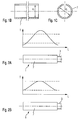
- 2A and 2B show two schematic diagrams of the distribution of the temperature T in an actuator module 1 without sleeve 7 and with sleeve 7 respectively as a function of the location L.
- the sleeve 7 results in a temperature distribution according to FIG. 2B.
- the Temperturmaximum in the axial center of the actuator module is lower, the temperature in the end regions significantly higher than in Fig. 2A, since the metallic sleeve 7 can dissipate the heat from the center into the end regions.
- the power dissipation of the piezoelectric or magnetostrictive element 2 is approximately proportional to the rotational speed of the internal combustion engine and the power loss is proportional to the maximum temperature in the piezoelectric or magnetostrictive element 2, the use of the sleeve 7 thus allows higher speeds of the internal combustion engine.
- the invention is not limited to the illustrated embodiment and is particularly applicable to a variety of fuel injector designs. Also, all features of the embodiment can be combined with each other.
Description
Die Erfindung geht aus von einem piezoelektrischen oder magnetostriktiven Aktormodul nach der Gattung des Hauptanspruchs.The invention is based on a piezoelectric or magnetostrictive actuator module according to the preamble of the main claim.
Beispielsweise ist aus der DE 198 56 186 A1 ein piezoelektrischer Aktor bekannt, welcher insbesondere zur Betätigung von Steuerventilen oder Einspritzventilen an Verbrennungsmotoren in Kraftfahrzeugen dient, wobei der Aktor einen piezoelektrischen Aktorkörper, insbesondere in Form eines vielschichtigen Laminats aus aufeinandergeschichteten Lagen piezoelektrischen Materials und dazwischenliegenden metallischen bzw. elektrisch leitenden Schichten, aufweist. Eine der Stirnseiten des Aktorkörpers ist an einem Aktorfuß festgelegt. Der Aktorkörper ist unter Einhaltung eines Zwischenraums von einer Modulwand umgeben, wobei der Zwischenraum mit einem elastischen oder plastischen, elektrisch isolierenden Stoff guter Wärmeleitfähigkeit ausgefüllt ist.For example, a piezoelectric actuator is known from DE 198 56 186 A1, which is used in particular for actuating control valves or injectors on internal combustion engines in motor vehicles, wherein the actuator is a piezoelectric actuator body, in particular in the form of a multi-layer laminate of stacked layers of piezoelectric material and intervening metallic or electrically conductive layers. One of the end faces of the actuator body is fixed to an actuator base. The actuator body is surrounded by a module wall while maintaining a gap, wherein the gap is filled with an elastic or plastic, electrically insulating material good thermal conductivity.
Nachteilig an dem aus der DE 198 56 186 A1 bekannten Aktor sind insbesondere die hohen Fertigungskosten und der hohe Fertigungsaufwand. Diese sind dadurch bedingt, daß der Aktor mittels eines Federbandes vorgespannt wird und die Aktorumspritzung deshalb mit einem relativ dünnflüssigen Material erfolgen muß, um das Aktormodul zum einen allseits ohne Hohlräume umgeben zu können und zum anderen die Elastizität zu erhalten. Die Anforderungen an das Umspritzungsmaterial sind daher sehr hoch, wodurch das Material teuer wird.A disadvantage of the known from DE 198 56 186 A1 actuator are in particular the high production costs and high production costs. These are due to the fact that the actuator is biased by a spring band and the Aktorumspritzung therefore must be done with a relatively thin liquid material in order to be able to surround the actuator module on the one hand everywhere without cavities and on the other to obtain the elasticity. The requirements for the Umspritzungsmaterial are therefore very high, whereby the material is expensive.
Weiterhin ist von Nachteil, daß eine Zentrierung des Aktors praktisch nicht möglich ist und der Aktorkörper dementsprechend von einem geräumigen Zwischenraum umgeben sein muß, was wiederum die Größe des Gesamtbauteils negativ beeinflußt.A further disadvantage is that a centering of the actuator is practically impossible and the actuator body must accordingly be surrounded by a spacious gap, which in turn adversely affects the size of the overall component.
Zudem kann der Aktor aufgrund seine Empfindlichkeit gegenüber Scherkräften während der Umspritzung beschädigt werden, wodurch sich die Herstellungskosten weiter erhöhen.In addition, the actuator can be damaged due to its sensitivity to shear forces during the encapsulation, thereby further increasing the manufacturing cost.
Aus der DE 199 14 411 A1 ist ein piezoelektrischer Aktor bekannt, bei dem ein Aktorkörper in eine Axialbohrung eines Ventilgehäuses eingesetzt wird. Hierbei ist der Außendurchmesser des Aktorkörpers etwas größer als der Innendurchmesser des Axialbohrung.From DE 199 14 411 A1 a piezoelectric actuator is known, in which an actuator body is inserted into an axial bore of a valve housing. Here, the outer diameter of the actuator body is slightly larger than the inner diameter of the axial bore.
In der WO 01/91197 A1 wird ein Aktor vorgestellt, bei dem sich das Aktormodul innerhalb einer Hülse mit Ausnehmungen, zum Beispiel Löcher oder Schlitze, befindet. Diese Hülse ist von einem wärmeleitfähigen Elastomer umgeben.In WO 01/91197 A1 an actuator is presented in which the actuator module is located within a sleeve with recesses, for example holes or slots. This sleeve is surrounded by a thermally conductive elastomer.
Das erfindungsgemäß ausgestaltete Aktormodul mit den Merkmalen des Hauptanspruchs hat demgegenüber den Vorteil, daß eine auf das Aktormodul aufgeklipste geschlitzte metallische Hülse, welche eine hohe Wärmeleitfähigkeit aufweist, die thermische Anbindung des Aktormoduls an ein Aktorgehäuse gewährleistet. Ein solches Aktormodul ist einfach und kostengünstig mit geringem Aufwand herstellbar.The inventively designed actuator module with the features of the main claim has the advantage that a clipped onto the actuator module slotted metallic sleeve, which has a high thermal conductivity, ensures the thermal connection of the actuator module to an actuator housing. Such an actuator module is simple and inexpensive to produce with little effort.
Durch die in den Unteransprüchen aufgeführten Maßnahmen sind vorteilhafte Weiterbildungen und Verbesserungen des im Hauptanspruch angegebenen Aktors möglich.The measures listed in the dependent claims advantageous refinements and improvements of the main claim actuator are possible.
Vorteilhafterweise besteht die Hülse aus Metall, insbesondere aus den hoch wärmeleitfähigen Metallen Kupfer oder Aluminium.Advantageously, the sleeve is made of metal, in particular of the highly thermally conductive metals copper or aluminum.
Zudem ist vorteilhaft, daß die Hülse geschlitzt und in einfacher Weise durch Stanzen und Biegen in einer beliebigen Wandstärke von ca. 0,2 bis 0,6 mm herstellbar ist.In addition, it is advantageous that the sleeve is slotted and can be produced in a simple manner by punching and bending in any wall thickness of about 0.2 to 0.6 mm.
Ein Ausführungsbeispiel der Erfindung ist in der Zeichnung vereinfacht dargestellt und in der nachfolgenden Beschreibung näher erläutert. Es zeigen:
- Fig. 1A
- eine schematische geschnittene Ansicht eines erfindungsgemäß ausgestalteten piezoelektrischen Aktormoduls,
- Fig. 1B
- eine auszugsweise schematische Ansicht der Hülse des in Fig. 1A dargestellten erfindungsgemäß ausgebildeten Aktormoduls in einer geschnittenen Ansicht,
- Fig. 1C
- einen Schnitt senkrecht zur Längsachse der in Fig. 1B dargestellten Hülse und
- Fig. 2A-B
- eine schematische Darstellung des Temperaturverlaufs über die Länge des Aktormoduls ohne und mit der erfindungsgemäßen Hülse.
- Fig. 1A
- FIG. 2 a schematic sectional view of a piezoelectric actuator module configured according to the invention, FIG.
- Fig. 1B
- 1 is a schematic sectional view of the sleeve of the actuator module according to the invention shown in FIG. 1A, in a sectional view,
- Fig. 1C
- a section perpendicular to the longitudinal axis of the sleeve shown in Fig. 1B and
- Fig. 2A-B
- a schematic representation of the temperature profile over the length of the actuator module without and with the sleeve according to the invention.
Ein in Fig. 1A dargestelltes Aktormodul 1 dient z. B. zur Betätigung eines Brennstoffeinspritzventils, welches insbesondere zur direkten Einspritzung von Brennstoff in den Brennraum einer gemischverdichtenden, selbst- oder fremdgezündeten Brennkraftmaschine geeignet ist.An illustrated in Fig. 1A actuator module 1 is used for. B. for actuating a fuel injection valve, which is particularly suitable for direct injection of fuel into the combustion chamber of a mixture-compressing, self-or spark-ignited internal combustion engine.
Das Aktormodul 1 besteht aus einem piezoelektrischen oder magnetostriktiven Element 2. Dieses kann sowohl monolithisch ausgeführt sein als auch aus scheibenförmigen piezoelektrischen oder magnetostriktiven Schichten bestehen, welche untereinander verklebt sein können.The actuator module 1 consists of a piezoelectric or magnetostrictive element 2. This can be carried out both monolithic as well as disc-shaped piezoelectric or magnetostrictive layers, which can be glued together.
Das Aktormodul 1 ist mit Kontaktstiften 3 zur Kontaktierung versehen. Die Kontaktstifte 3 und das piezoelektrische oder magnetostriktive Element 2 sind von einer Umspritzung 4 umgeben, in welche die Kontaktstifte 3 eingebettet sind. Außerhalb der Umspritzung 4 sind die Kontaktstifte 3 von Isolierhülsen 5 umgeben. Die Umspritzung 4 wird dabei durch eine Kunststoffhülse 6 geformt, welche über das piezoelektrische oder magnetostriktive Element 2 geschoben und dann mit der Spritzgußmasse für die Umspritzung 4 gefüllt wird. Die Umspritzung 4 dient der Wärmeableitung der durch das piezoelektrische oder magnetostriktive Element 2 erzeugten Verlustwärme während des Betriebs.The actuator module 1 is provided with
Nach dem Anbringen der Umspritzung 4 ist das Aktormodul 1 für weitere Montageschritte wie das Vorspannen und das Einsetzen in eine nicht weiter dargestellte Rohrfeder bereit. Da die Umspritzung 4 und die Rohrfeder aus fertigungstechnischen Gründen nicht in direktem Kontakt mit der Rohrfeder stehen, müssen entsprechende Maßnahmen ergriffen werden, um das Aktormodul 1 thermisch an die Rohrfeder bzw. ein diese umschließendes Aktorgehäuse zu koppeln.After attaching the
Zu diesem Zweck ist erfindungsgemäß eine Hülse 7 vorgesehen, welche die Kunststoffhülse 6 umschließt. Wie aus Fig. 1B und 1C ersichtlich, ist die Hülse 7 dabei in Form einer geschlitzten Hülse 7 ausgebildet, deren Innendurchmesser di geringfügig kleiner ist als ein Außendurchmesser da des Aktormoduls 1. Dadurch kann erreicht werden, daß die auf das Aktormodul 1 aufgeklipste Hülse 7 im montierten Zustand überall gut an der Kunststoffhülse 6 anliegt und ein optimaler Wärmeübergang vom Aktormodul in die Hülse 7 stattfinden kann.For this purpose, a
Die Hülse 7 ist vorzugsweise aus Metall durch Stanzen und anschließendes Biegen hergestellt, was eine einfache, schnelle und kostengünstige Herstellung ermöglicht. Als Material wird vorzugsweise Aluminium, Kupfer, eine Legierung hieraus oder ein anderes Metall oder eine andere Legierung, z. B. Messing, mit hoher Wärmeleitfähigkeit verwendet. Die Wandstärke der Hülse 7 beträgt dabei etwa 0,2 bis 0,6 mm.The
Fig. 2A und 2B zeigen zwei schematische Diagramme der Verteilung der Temperatur T in einem Aktormodul 1 ohne Hülse 7 und mit Hülse 7 jeweils als Funktion des Orts L.2A and 2B show two schematic diagrams of the distribution of the temperature T in an actuator module 1 without
Ohne die Hülse 7 ergibt sich eine Temperaturverteilung gemäß Fig. 2A. Da die axiale Wärmeleitfähigkeit des piezoelektrischen oder magnetostriktiven Elements 2 relativ gering ist, wird das Aktormodul 1 in der Mitte seiner axialen Erstreckung sehr warm. An den Enden ist die Temperatur deutlich geringer, da Wärme über die Stirnflächen abgeleitet wird.Without the
Mit der Hülse 7 ergibt sich eine Temperaturverteilung gemäß Fig. 2B. Das Temperturmaximum in der axialen Mitte des Aktormoduls ist geringer, die Temperatur in den Endbereichen deutlich höher als in Fig. 2A, da die metallische Hülse 7 die Wärme von der Mitte in die Endbereiche abführen kann.The
Da die Verlustleistung des piezoelektrischen oder magnetostriktiven Elements 2 ungefähr proportional zur Drehzahl der Brennkraftmaschine ist und die Verlustleistung proportional zur maximalen Temperatur in dem piezoelektrischen oder magnetostriktiven Element 2 ist, ermöglicht die Verwendung der Hülse 7 somit höhere Drehzahlen der Brennkraftmaschine.Since the power dissipation of the piezoelectric or magnetostrictive element 2 is approximately proportional to the rotational speed of the internal combustion engine and the power loss is proportional to the maximum temperature in the piezoelectric or magnetostrictive element 2, the use of the
Die Erfindung ist nicht auf das dargestellte Ausführungsbeispiel beschränkt und insbesondere bei einer Vielzahl von Bauweisen von Brennstoffeinspritzventilen anwendbar. Auch sind alle Merkmale des Ausführungsbeispiels beliebig miteinander kombinierbar.The invention is not limited to the illustrated embodiment and is particularly applicable to a variety of fuel injector designs. Also, all features of the embodiment can be combined with each other.
Claims (7)
- Actuator module (1), in particular for operation of fuel injection valves (1) for fuel injection systems for internal combustion engines, having at least one piezoelectric or magnetostrictive element (2) and contact pins (3) for making electrical contact with the piezoelectric or magnetostrictive element (2),
with the actuator module (1) having an extruded coating (4) and with the actuator module (1) being surrounded by a sleeve (7) whose internal diameter (di) is slightly smaller than the external diameter (da) of the actuator module (1) without the sleeve (7),
characterized in that
the sleeve (7) is axially slotted. - Actuator module according to Claim 1, characterized in that the sleeve (7) rests over its complete area on a plastic sleeve (6) of the actuator module (1).
- Actuator module according to one of Claims 1 or 2, characterized in that the sleeve (7) is composed of metal.
- Actuator module according to Claim 3, characterized in that the sleeve is composed of copper or aluminium, or of an alloy of them.
- Actuator module according to one of Claims 1 to 4, characterized in that the sleeve (7) has a wall thickness of 0.2 to 0.6 mm.
- Actuator module according to one of Claims 1 to 5, characterized in that the sleeve (7) is produced by means of stamping and bending.
- Actuator module according to one of Claims 1 to 6, characterized in that the sleeve (7) allows thermal coupling of the actuator module (1) to further components.
Applications Claiming Priority (2)
| Application Number | Priority Date | Filing Date | Title |
|---|---|---|---|
| DE10350061A DE10350061A1 (en) | 2003-10-27 | 2003-10-27 | actuator module |
| DE10350061 | 2003-10-27 |
Publications (3)
| Publication Number | Publication Date |
|---|---|
| EP1528606A2 EP1528606A2 (en) | 2005-05-04 |
| EP1528606A3 EP1528606A3 (en) | 2005-08-10 |
| EP1528606B1 true EP1528606B1 (en) | 2007-06-06 |
Family
ID=34399561
Family Applications (1)
| Application Number | Title | Priority Date | Filing Date |
|---|---|---|---|
| EP04105078A Expired - Fee Related EP1528606B1 (en) | 2003-10-27 | 2004-10-15 | Actuator module |
Country Status (2)
| Country | Link |
|---|---|
| EP (1) | EP1528606B1 (en) |
| DE (2) | DE10350061A1 (en) |
Families Citing this family (4)
| Publication number | Priority date | Publication date | Assignee | Title |
|---|---|---|---|---|
| DE102006022997A1 (en) * | 2006-05-17 | 2007-11-22 | Robert Bosch Gmbh | piezo actuator |
| DE102006026931A1 (en) * | 2006-06-09 | 2007-12-13 | Siemens Ag | Piezo-actuator for use in injector, has tube-like housing provided with outer wall, and piezo-stack that is arranged within tube-like housing, where cooling body is fastened to outer wall of housing |
| DE102006026932A1 (en) * | 2006-06-09 | 2007-12-13 | Siemens Ag | Piezo-actuator for use as part of injector for common rail diesel fuel injection system, has air gap between outer side of spring and inner wall of housing, and punched and/or curved sheet metal heat guiding plate arranged in air gap |
| FR2944144A3 (en) * | 2009-04-03 | 2010-10-08 | Renault Sas | Piezoelectric or magnetostrictive actuator for use in fuel injector of heat engine, has maintaining unit comprising unique element and shells for forming wall portion, where element and shells exert radial elastic force on cylindrical stack |
Family Cites Families (8)
| Publication number | Priority date | Publication date | Assignee | Title |
|---|---|---|---|---|
| US5148077A (en) * | 1990-09-28 | 1992-09-15 | Caterpillar Inc. | Coating surrounding a piezoelectric solid state motor stack |
| DE19650900A1 (en) * | 1996-12-07 | 1998-06-10 | Bosch Gmbh Robert | Piezoelectric actuator |
| DE19715488C1 (en) * | 1997-04-14 | 1998-06-25 | Siemens Ag | Piezoelectric actuator |
| DE19753930A1 (en) * | 1997-12-05 | 1999-06-10 | Ceramtec Ag | Process for attaching external electrodes to solid state actuators |
| DE19914411A1 (en) * | 1999-03-30 | 2000-10-12 | Bosch Gmbh Robert | Piezoelectric actuator |
| DE10025997A1 (en) * | 2000-05-25 | 2001-12-06 | Bosch Gmbh Robert | Piezo actuator |
| DE10054017A1 (en) * | 2000-11-01 | 2002-05-08 | Bosch Gmbh Robert | Piezo-actuator module, especially for fuel injection system, has sheath element designed as heat-conducting rubber element which has shell-shaped design and lies directly on piezo-actuator |
| JP2002203997A (en) * | 2000-12-28 | 2002-07-19 | Denso Corp | Piezoelectric actuator |
-
2003
- 2003-10-27 DE DE10350061A patent/DE10350061A1/en not_active Withdrawn
-
2004
- 2004-10-15 DE DE502004004016T patent/DE502004004016D1/en active Active
- 2004-10-15 EP EP04105078A patent/EP1528606B1/en not_active Expired - Fee Related
Non-Patent Citations (1)
| Title |
|---|
| None * |
Also Published As
| Publication number | Publication date |
|---|---|
| EP1528606A2 (en) | 2005-05-04 |
| EP1528606A3 (en) | 2005-08-10 |
| DE10350061A1 (en) | 2005-05-25 |
| DE502004004016D1 (en) | 2007-07-19 |
Similar Documents
| Publication | Publication Date | Title |
|---|---|---|
| EP1082567B1 (en) | Piezoelectric actuator | |
| DE19818068A1 (en) | Piezo-electronic actuator for an actuator | |
| EP1829128A2 (en) | Device comprising a shape memory element | |
| EP1528606B1 (en) | Actuator module | |
| DE102004004706A1 (en) | Cable bushing and fuel system part with a cable bushing | |
| WO2007131965A1 (en) | Piezoactuator | |
| DE102006059693A1 (en) | Pressure measuring device | |
| DE19630208A1 (en) | Glow plug | |
| DE10048430A1 (en) | Piezoelectric actuator, e.g. for control valves in vehicles, has piezoelectric material and metal or electrical conducting layers forming actuator body and gap provided between body and enclosing jacket is filled with liquid medium | |
| DE10360451A1 (en) | Fuel injection valve with a piezoelectric or magnetorestrictive actuator for a combustion engine has hydraulic coupling with flexible section having a restricted outer expansion | |
| EP1528607B1 (en) | Actuator module | |
| WO2005116442A1 (en) | Injection valve and method for the production thereof | |
| DE102006032743A1 (en) | Actuator for lift drive of actuating element, particularly valve needle in fuel injection valve, has actuator connecting cable connected firmly with contact points by assembly of contact points in surface of actuator bearing | |
| DE10040239B4 (en) | Noise-damped actuator unit | |
| DE10317148B4 (en) | Fuel injector | |
| DE102006001573A1 (en) | Piezo actuator with improved safety against short circuits | |
| EP1577960B1 (en) | Actuator module | |
| DE102009027101A1 (en) | Flexible casing for piezoelectric actuator for fuel injection system of air compression, self ignition internal combustion engine, has internal recesses, where is positioned partially against outer surface of actuator in expanded condition | |
| EP3036431B1 (en) | Piezo actuator for a fuel injector, and fuel injector | |
| WO2012069235A1 (en) | Piezoelectric actuator module, and fuel injection valve | |
| EP1919004B1 (en) | Piezo actuator module or piezo actuator with a cladded protection layer system | |
| EP1919005A2 (en) | Assembly of a piezo actuator in the casing of a piezo actuator module | |
| DE10356961A1 (en) | Actuator module for fuel injection valves has pin with good heat conductivity characteristics, which transfers the heat away from the actuator | |
| DE102009020270A1 (en) | actuator | |
| DE102006060651A1 (en) | Piezoelectric actuator |
Legal Events
| Date | Code | Title | Description |
|---|---|---|---|
| PUAI | Public reference made under article 153(3) epc to a published international application that has entered the european phase |
Free format text: ORIGINAL CODE: 0009012 |
|
| AK | Designated contracting states |
Kind code of ref document: A2 Designated state(s): AT BE BG CH CY CZ DE DK EE ES FI FR GB GR HU IE IT LI LU MC NL PL PT RO SE SI SK TR |
|
| AX | Request for extension of the european patent |
Extension state: AL HR LT LV MK |
|
| PUAL | Search report despatched |
Free format text: ORIGINAL CODE: 0009013 |
|
| AK | Designated contracting states |
Kind code of ref document: A3 Designated state(s): AT BE BG CH CY CZ DE DK EE ES FI FR GB GR HU IE IT LI LU MC NL PL PT RO SE SI SK TR |
|
| AX | Request for extension of the european patent |
Extension state: AL HR LT LV MK |
|
| 17P | Request for examination filed |
Effective date: 20060210 |
|
| AKX | Designation fees paid |
Designated state(s): DE FR GB IT |
|
| GRAP | Despatch of communication of intention to grant a patent |
Free format text: ORIGINAL CODE: EPIDOSNIGR1 |
|
| GRAS | Grant fee paid |
Free format text: ORIGINAL CODE: EPIDOSNIGR3 |
|
| GRAA | (expected) grant |
Free format text: ORIGINAL CODE: 0009210 |
|
| AK | Designated contracting states |
Kind code of ref document: B1 Designated state(s): DE FR GB IT |
|
| REG | Reference to a national code |
Ref country code: GB Ref legal event code: FG4D Free format text: NOT ENGLISH |
|
| REF | Corresponds to: |
Ref document number: 502004004016 Country of ref document: DE Date of ref document: 20070719 Kind code of ref document: P |
|
| GBT | Gb: translation of ep patent filed (gb section 77(6)(a)/1977) |
Effective date: 20070831 |
|
| ET | Fr: translation filed | ||
| PLBE | No opposition filed within time limit |
Free format text: ORIGINAL CODE: 0009261 |
|
| STAA | Information on the status of an ep patent application or granted ep patent |
Free format text: STATUS: NO OPPOSITION FILED WITHIN TIME LIMIT |
|
| 26N | No opposition filed |
Effective date: 20080307 |
|
| PGFP | Annual fee paid to national office [announced via postgrant information from national office to epo] |
Ref country code: DE Payment date: 20141208 Year of fee payment: 11 Ref country code: FR Payment date: 20141021 Year of fee payment: 11 Ref country code: GB Payment date: 20141024 Year of fee payment: 11 |
|
| PGFP | Annual fee paid to national office [announced via postgrant information from national office to epo] |
Ref country code: IT Payment date: 20141027 Year of fee payment: 11 |
|
| REG | Reference to a national code |
Ref country code: DE Ref legal event code: R119 Ref document number: 502004004016 Country of ref document: DE |
|
| GBPC | Gb: european patent ceased through non-payment of renewal fee |
Effective date: 20151015 |
|
| PG25 | Lapsed in a contracting state [announced via postgrant information from national office to epo] |
Ref country code: IT Free format text: LAPSE BECAUSE OF NON-PAYMENT OF DUE FEES Effective date: 20151015 Ref country code: DE Free format text: LAPSE BECAUSE OF NON-PAYMENT OF DUE FEES Effective date: 20160503 Ref country code: GB Free format text: LAPSE BECAUSE OF NON-PAYMENT OF DUE FEES Effective date: 20151015 |
|
| REG | Reference to a national code |
Ref country code: FR Ref legal event code: ST Effective date: 20160630 |
|
| PG25 | Lapsed in a contracting state [announced via postgrant information from national office to epo] |
Ref country code: FR Free format text: LAPSE BECAUSE OF NON-PAYMENT OF DUE FEES Effective date: 20151102 |