EP1528576A2 - Electrical insulator - Google Patents
Electrical insulator Download PDFInfo
- Publication number
- EP1528576A2 EP1528576A2 EP04025657A EP04025657A EP1528576A2 EP 1528576 A2 EP1528576 A2 EP 1528576A2 EP 04025657 A EP04025657 A EP 04025657A EP 04025657 A EP04025657 A EP 04025657A EP 1528576 A2 EP1528576 A2 EP 1528576A2
- Authority
- EP
- European Patent Office
- Prior art keywords
- electrical insulator
- shed
- metal part
- airflow
- sheds
- Prior art date
- Legal status (The legal status is an assumption and is not a legal conclusion. Google has not performed a legal analysis and makes no representation as to the accuracy of the status listed.)
- Withdrawn
Links
Images






Classifications
-
- H—ELECTRICITY
- H01—ELECTRIC ELEMENTS
- H01B—CABLES; CONDUCTORS; INSULATORS; SELECTION OF MATERIALS FOR THEIR CONDUCTIVE, INSULATING OR DIELECTRIC PROPERTIES
- H01B17/00—Insulators or insulating bodies characterised by their form
- H01B17/14—Supporting insulators
- H01B17/18—Supporting insulators for very heavy conductors, e.g. bus-bars, rails
Definitions
- the present invention relates to an electrical insulator, and more specifically relates to means for reducing aerodynamic noise caused by an electrical insulator for a current collector of a railway vehicle which moves at a high velocity.
- Aerodynamic noise caused by a railway vehicle moving at a high velocity increases proportionally to about 6th to 8th power of the velocity. Therefore, noise significantly increases as the velocity increases. On the other hand, it is expected that requirements for environmental protection will further increase.
- high-velocity railway vehicles are expected to reduce the noise caused by current collector, which is the main source of aerodynamic noise, and noise reduction of the electrical insulator included in the current collector is also required accordingly.
- JP2002-329433A discloses an electrical insulator with a noise reduction structure in which the electrical insulator has an elliptical or oval cross section and includes three or more kinds of sheds having different shed diameters, the three or more kinds of sheds being alternately and repeatedly arranged (see JP2002-329433A, pages 2 to 3, Figs. 1 to 11).
- the above-described known structure can reduce noise when air is flowing parallel to the sheds of the electrical insulator.
- the airflow has a velocity in the vertical direction and does not flow parallel to the sheds when seen from the side, separation of the airflow occurs at the sheds and an upper metal part of the electrical insulator, and noise is generated accordingly.
- a structural component is placed on top of the electrical insulator, turbulent airflow is caused by the structural component and noise is generated when the turbulent airflow hits a shed.
- the electrical insulator is provided with upper and lower metal parts having smooth surfaces, and the velocity of the airflow is increased on the smooth surfaces. Then, a large degree of airflow separation and periodic vortex shedding occur, and noise is generated accordingly.
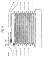
- Fig. 11 is a side view showing an airflow field around an electrical insulator of prior arts obtained by numerical simulation.
- Fig. 12 is a perspective view showing an airflow field around an actual electrical insulator for a current collector obtained by numerical simulation.
- the electrical insulator includes a column 21 for supporting a collector shoe on the electrical insulator, a conductor cable, etc.
- the main factors that cause the noise are the separation of the airflow at the front and the collision of the vortices generated at positions downstream of a structural component placed on top of the electrical insulator with other members.
- An object of the present invention is to provide an electrical insulator which can reduce noise even when the airflow has a vertical velocity relative to the electrical insulator.
- an electrical insulator includes a shed having a diameter larger than the shed diameter of the electrical insulator in an upper portion of the electrical insulator.
- an electrical insulator having an upper metal part includes a shed having a diameter larger than the shed diameter of the electrical insulator in an upper portion of the electrical insulator, the shed being integrated with the upper metal part.
- the shed may have an elliptical or oval cross section.
- the shed may also have a circular cross section.
- an electrical insulator having an upper metal part and a lower metal part includes one or more sheds on the surface of at least one of the upper metal part and the lower metal part.
- an electrical insulator having an upper metal part and a lower metal part includes at least two kinds of sheds having different diameters on the surface of at least one of the upper metal part and the lower metal part.
- each of the sheds may have an elliptical or oval cross section.
- each of the sheds may also have a circular cross section.
- the airflow in the vertical direction of the electrical insulator is reduced.
- an electrical insulator has an elliptical or oval cross section and includes an elliptical or oval shed with a diameter larger than the shed diameter of the electrical insulator in an upper portion of the electrical insulator.
- the electrical insulator includes an upper metal part in the upper portion of the electrical insulator and a lower metal part in a lower portion of the electrical insulator, and the upper and lower metal parts are provided with two or more kinds of sheds having different shed diameters.
- the shed with the elliptical or oval cross section provided in the upper portion of the electrical insulator may be integrated with the upper metal part.
- Fig. 1 is a sectional view showing the structure of an electrical insulator according to a first embodiment of the present invention
- Fig. 2 is a side view of the electrical insulator.
- An electrical insulator 1 includes a splitter plate 31 on the top surface of an upper metal part 2, the splitter plate 31 defining a shed with a diameter larger than the shed diameter of the electrical insulator 1.
- the splitter plate 31 has an elliptical or oval cross section and is substantially streamlined so that airflow turbulence is minimized and the splitter plate 31 does not generate aerodynamic noise by itself.
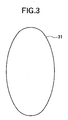
- Fig. 3 is a top view of the electrical insulator according to the first embodiment of the present invention. Since the splitter plate 31 has a diameter larger than the shed diameter of the electrical insulator 1, only the splitter plate 31 can be viewed from above.
- Fig. 4 is a side view showing an airflow according to the first embodiment. Due to the shape of the splitter plate 31, upward airflow at the front of the electrical insulator 1 is reduced and the airflow is substantially parallel to the sheds. Thus, the airflow separation in the front region of a shed of the electrical insulator 1 is suppressed. As a result, pressure fluctuation on the surface, which is the cause of noise, is reduced and the noise is reduced accordingly.
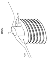
- Fig. 5 is a perspective view showing the airflow according to the first embodiment. Since the splitter plate 31 is provided, the airflow in the vertical direction is reduced. Accordingly, the pressure fluctuation caused by the airflow separation in the front region of the electrical insulator 1 is also reduced. Although vortices 103 are generated by a column 21 for supporting a collector shoe and flow downstream, they do not move downward since the vertical airflow is reduced. Accordingly, the pressure fluctuation caused by the vortices 103 on the shed of the electrical insulator 1 is reduced.
- Fig. 6 is a sectional view showing the structure of an electrical insulator according to a second embodiment of the present invention as seen from the front.
- the splitter plate 31 having a diameter larger than the shed diameter of the electrical insulator 1 is provided on the top surface of the upper metal part 2.
- a ring-shaped splitter plate 31 is fitted around an upper metal part 2.
- the pressure fluctuation on the surface which is the cause of aerodynamic noise, is reduced and the noise is reduced accordingly.
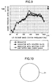
- Fig. 9 is a diagram showing the result of wind tunnel tests for measuring the noise caused by the electrical insulators according to the first to third embodiments of the present invention.
- the noise is largely reduced in a frequency range of 200 Hz or more when the splitter plate is provided.
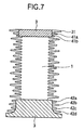
- Fig. 7 is a sectional view showing the structure of an electrical insulator according to a third embodiment of the present invention as seen from the front, and Fig. 8 is a side view of the electrical insulator.
- the moving direction is shown by A.
- the third embodiment is different from the first embodiment in that an upper metal part 2 and a lower metal part 3 of an electrical insulator 1 are provided with two or more kinds of sheds 41a to 42d having different shed diameters and elliptical or oval cross sections.
- the upper metal part 2 and the lower metal part 3, which are exposed to the airflow, have side surfaces with smooth, uniform cross sections. Accordingly, Karman vortices are generated due to velocity shear layers at boundaries between the main flow and separation regions on the smooth surfaces, and this is considered to generate Aeolian tones.
- vent holes in the electrical insulator 1 since a conductor cable and the like are disposed in the electrical insulator 1.
- the sheds 41a to 42d are provided on the upper metal part 2 and the lower metal part 3 so as to suppress the airflow-accelerating function of the metal part surfaces and to control the separation of the airflow from the surfaces of the metal parts 2 and 3.
- vortex areas at the downstream are controlled and the vortex diameters are reduced. It is not necessary that the sheds 41a to 42d on the metal parts 2 and 3 be electrically insulative.
- aerodynamic noise caused by the upper metal part and the lower metal part is reduced and noise generated by the overall body of the electrical insulator is reduced accordingly.
- Fig. 10 is a top view of an electrical insulator according to a fourth embodiment of the present invention.
- the fourth embodiment is different from the above-described first to third embodiment in that a splitter plate 31 and sheds provided on an upper metal part 2 and a lower metal part 3 of an electrical insulator have circular cross sections. Also in this case, noise can be reduced similar to the first to third embodiments.
- the electrical insulator according to the fourth embodiment which is provided with the sheds having circular cross sections has no directionality in cross section, and accordingly the application thereof is not limited to current collectors for high-velocity railway vehicles. More specifically, when the electrical insulator according to the fourth embodiment is used in transmission towers which receive strong wind of typhoon or snowstorm, sea wind, etc., it can reduce noise caused by wind blowing from any direction in cross section.
Landscapes
- Insulators (AREA)
- Current-Collector Devices For Electrically Propelled Vehicles (AREA)
Abstract
Description
Claims (8)
- An electrical insulator (1) characterized by comprising a shed (31) having a diameter larger than the shed diameter of the electrical insulator (1) in an upper portion of the electrical insulator (1).
- An electrical insulator (1) having an upper metal part (2), characterized by comprising a shed (31) having a diameter larger than the shed diameter of the electrical insulator (1) in an upper portion of the electrical insulator (1), the shed (31) being integrated with the upper metal part (2).
- The electrical insulator (1) according to one of Claims 1 and 2, wherein the shed (31) has an elliptical or oval cross section.
- The electrical insulator (1) according to one of Claims 1 and 2, wherein the shed (31) has a circular cross section.
- An electrical insulator (1) having an upper metal part (2) and a lower metal part (3), characterized by comprising one or more sheds (41a, 41b, 42a, 42b, 42c, 42d) on the surface of at least one of the upper metal part (2) and the lower metal part (3).
- An electrical insulator (1) having an upper metal part (2) and a lower metal part (3), characterized by comprising at least two kinds of sheds (41a, 41b, 42a, 42b, 42c, 42d) having different diameters on the surface of at least one of the upper metal part (2) and the lower metal part (3).
- An electrical insulator (1) according to one of Claims 5 and 6, wherein each of the sheds (41a, 41b, 42a, 42b, 42c, 42d) has an elliptical or oval cross section.
- An electrical insulator (1) according to one of Claims 5 and 6, wherein each of the sheds (41a, 41b, 42a, 42b, 42c, 42d) has a circular cross section.
Applications Claiming Priority (2)
| Application Number | Priority Date | Filing Date | Title |
|---|---|---|---|
| JP2003367240 | 2003-10-28 | ||
| JP2003367240A JP4332718B2 (en) | 2003-10-28 | 2003-10-28 | Insulator |
Publications (2)
| Publication Number | Publication Date |
|---|---|
| EP1528576A2 true EP1528576A2 (en) | 2005-05-04 |
| EP1528576A3 EP1528576A3 (en) | 2006-02-01 |
Family
ID=34420122
Family Applications (1)
| Application Number | Title | Priority Date | Filing Date |
|---|---|---|---|
| EP04025657A Withdrawn EP1528576A3 (en) | 2003-10-28 | 2004-10-28 | Electrical insulator |
Country Status (2)
| Country | Link |
|---|---|
| EP (1) | EP1528576A3 (en) |
| JP (1) | JP4332718B2 (en) |
Cited By (4)
| Publication number | Priority date | Publication date | Assignee | Title |
|---|---|---|---|---|
| CN104590030A (en) * | 2014-12-12 | 2015-05-06 | 株洲鼎顺新材料科技有限公司 | Bus brace and pantograph brace porcelain insulator on roof of electric locomotive |
| CN107946005A (en) * | 2017-05-27 | 2018-04-20 | 国网新疆电力公司经济技术研究院 | A kind of wind resistance composite insulator applied to strong wind area |
| DE102019121932A1 (en) * | 2019-08-14 | 2021-02-18 | Bombardier Transportation Gmbh | Insulator for a rail vehicle and pantograph |
| CN114551013A (en) * | 2022-02-24 | 2022-05-27 | 南京理工大学 | Anti-drag noise-reduction insulator and high-speed train pantograph with same |
Families Citing this family (1)
| Publication number | Priority date | Publication date | Assignee | Title |
|---|---|---|---|---|
| CN104269235A (en) * | 2014-10-17 | 2015-01-07 | 王玉华 | Opposite angular edge pillar anti-pollution-flashover insulator special for electric locomotives and motor train units |
Family Cites Families (4)
| Publication number | Priority date | Publication date | Assignee | Title |
|---|---|---|---|---|
| FR594268A (en) * | 1924-03-05 | 1925-09-09 | Porcelainfabrikken Norden As | Electrical insulator for high voltage |
| DE1093844B (en) * | 1959-03-20 | 1960-12-01 | Siemens Ag | Insulator, in particular support insulator made of glass fiber reinforced cast resin |
| FR2133473A1 (en) * | 1971-04-14 | 1972-12-01 | Gratzmuller J | Power line insulator - formed from assembly of moulded synthetic resin insulator elements |
| FR2604821B1 (en) * | 1986-10-02 | 1990-01-12 | Ceraver | COMPOSITE INSULATOR WITH OVER-MOLDED INSULATING COATING |
-
2003
- 2003-10-28 JP JP2003367240A patent/JP4332718B2/en not_active Expired - Fee Related
-
2004
- 2004-10-28 EP EP04025657A patent/EP1528576A3/en not_active Withdrawn
Cited By (6)
| Publication number | Priority date | Publication date | Assignee | Title |
|---|---|---|---|---|
| CN104590030A (en) * | 2014-12-12 | 2015-05-06 | 株洲鼎顺新材料科技有限公司 | Bus brace and pantograph brace porcelain insulator on roof of electric locomotive |
| CN107946005A (en) * | 2017-05-27 | 2018-04-20 | 国网新疆电力公司经济技术研究院 | A kind of wind resistance composite insulator applied to strong wind area |
| DE102019121932A1 (en) * | 2019-08-14 | 2021-02-18 | Bombardier Transportation Gmbh | Insulator for a rail vehicle and pantograph |
| DE102019121932B4 (en) | 2019-08-14 | 2024-11-21 | Bombardier Transportation Gmbh | Insulator for a rail vehicle and pantograph |
| CN114551013A (en) * | 2022-02-24 | 2022-05-27 | 南京理工大学 | Anti-drag noise-reduction insulator and high-speed train pantograph with same |
| CN114551013B (en) * | 2022-02-24 | 2024-06-18 | 南京理工大学 | Resistance-reducing noise-reducing insulator and high-speed train pantograph with same |
Also Published As
| Publication number | Publication date |
|---|---|
| JP2005135602A (en) | 2005-05-26 |
| JP4332718B2 (en) | 2009-09-16 |
| EP1528576A3 (en) | 2006-02-01 |
Similar Documents
| Publication | Publication Date | Title |
|---|---|---|
| KR101794780B1 (en) | Railway vehicle and method of manufacturing the same | |
| EP1528576A2 (en) | Electrical insulator | |
| CA2692403C (en) | Vibration resistant cable | |
| CN113471657A (en) | Antenna device | |
| JP3374469B2 (en) | Current collector | |
| US3296357A (en) | Device to prevent vibration of aerial conductors | |
| JP2004036271A (en) | Bridge | |
| JPH09266604A (en) | Low noise hull for pantograph of high speed vehicle | |
| JP3873184B2 (en) | Windproof cover for current collector | |
| JPH09205702A (en) | Single arm type pantograph | |
| JP2877121B2 (en) | Current collector sound insulation device | |
| JP2881632B2 (en) | Current collector support | |
| JP3630419B1 (en) | Windshield cover device for current collector in vehicle | |
| JP3640192B2 (en) | Insulator | |
| JPH04103494A (en) | Turbulence restraining device | |
| JP4286759B2 (en) | Cover device for vehicle roof projections | |
| JP3503267B2 (en) | Electric insulator for vehicles | |
| JP2007176192A (en) | Noise barrier for railway vehicles | |
| CN115102364B (en) | A permanent magnet eddy current brake | |
| JPH08126109A (en) | Pantograph cover having streamline body | |
| JPH0718627A (en) | Vibration control cable-stayed bridge cable | |
| JP2002320301A (en) | Noise reduction cover | |
| JP4997296B2 (en) | Rectifying cover | |
| CN120798063A (en) | Windbreak wall components | |
| JPH09182206A (en) | Current collector sound insulation device |
Legal Events
| Date | Code | Title | Description |
|---|---|---|---|
| PUAI | Public reference made under article 153(3) epc to a published international application that has entered the european phase |
Free format text: ORIGINAL CODE: 0009012 |
|
| AK | Designated contracting states |
Kind code of ref document: A2 Designated state(s): AT BE BG CH CY CZ DE DK EE ES FI FR GB GR HU IE IT LI LU MC NL PL PT RO SE SI SK TR |
|
| AX | Request for extension of the european patent |
Extension state: AL HR LT LV MK |
|
| PUAL | Search report despatched |
Free format text: ORIGINAL CODE: 0009013 |
|
| AK | Designated contracting states |
Kind code of ref document: A3 Designated state(s): AT BE BG CH CY CZ DE DK EE ES FI FR GB GR HU IE IT LI LU MC NL PL PT RO SE SI SK TR |
|
| AX | Request for extension of the european patent |
Extension state: AL HR LT LV MK |
|
| 17P | Request for examination filed |
Effective date: 20060613 |
|
| AKX | Designation fees paid |
Designated state(s): DE FR GB |
|
| 17Q | First examination report despatched |
Effective date: 20090709 |
|
| STAA | Information on the status of an ep patent application or granted ep patent |
Free format text: STATUS: THE APPLICATION IS DEEMED TO BE WITHDRAWN |
|
| 18D | Application deemed to be withdrawn |
Effective date: 20091120 |