The present invention relates to a device manufacturing method,
wherein a substrate is provided, wherein a projection beam of radiation is
provided using an illumination system, wherein patterning means are used to
impart the projection beam with a pattern in its cross-section, wherein the
patterned beam of radiation is projected onto a target portion of the substrate,
wherein at least part of the method is carried out in at least one chamber.
The invention further relates to a lithographic apparatus, particularly
for carrying out such a method.
Said device manufacturing method and said apparatus are known
from the art. The manufacturing method and lithographic apparatus can be
used, for example, in the manufacture of integrated circuits (ICs). In that
circumstance, a patterning means, such as a mask, may be used to generate a
circuit pattern corresponding to an individual layer of the IC, and this pattern
can be imaged onto target portions, comprising dies or die parts, on a substrate
(e.g. a silicon wafer) that has a layer of radiation-sensitive material (resist). In
general, a single substrate contains a network of target portions that are
successively exposed. Known lithographic apparatus include so-called
steppers, in which each target portion is irradiated by exposing an entire
pattern onto the target portion in one go, and so-called scanners, in which each
target portion is irradiated by scanning the pattern through said projection
beam in a given direction (the "scanning"-direction) while synchronously
scanning the substrate parallel or anti-parallel to this direction.
The known method can be at least partially carried out in vacuum, more
specifically in a vacuum chamber, and/or at atmospheric pressure. The
application of vacuum may be desired, for instance, to provide a relative
contamination free environment to carry out the manufacturing method, so
that devices having small features can be made with high precision. Besides,
the use of vacuum may be desired to prevent absorption of said projection
beam.
A problem of the known method is, that a large amount of residual
water may be present in the chamber, which may lead to degradation, for
example oxidation, of parts of said illumination system and/or said patterning
means used in the manufacturing method. The amount of water in said
chamber can even rise due to water which originates from the substrates to be
treated, which substrates are brought into the chamber from an environment
and may comprise adsorbed water. Said degradation of the illumination
system and/or patterning means may impair a desired imaging performance of
the manufacturing method. The degradation further leads to high
maintenance and operating cost, a low machine life time, a low productivity,
resulting in high costs of the devices manufactured thereby.
It is an object of the present invention to improve the device
manufacturing method. In particular, the invention aims to provide a device
manufacturing method which has a high availability and/or productivity.
According to an aspect of the invention, there is provided a device
manufacturing method which is characterized by the features of claim 1.
At least one chemical reagent is supplied to said chamber for removing water
from the chamber. Consequently, degradation of apparatus parts used in the
method, such as the projection system and/or patterning means, under the
influence of water can be prevented or at least diminished, which leads to
lower operating costs, a longer machine life time, resulting in cheaper devices
manufactured thereby. The chemical reagent can be supplied to said chamber,
for example, before, during and/or after said substrate is illuminated by said
projection beam. Besides, the chemical reagent can be used to achieve a certain
desired vacuum level relatively fast and easy, for the case that the chamber is
a vacuum chamber. The chemical reagent can, for instance, react with water to
form volatile substances. Besides, the chemical reagent can, for example, react
with water in a decomposition reaction, a complexation reaction and/or one or
more other reactions.
It is to be noted, that the paper "Quick acquisition of clean ultrahigh
vacuum by chemical process technology" of K. Tatenuma et al. (J. Vac. Sci.
Technol. A, Vol. 11, No. 4, Jul/Aug 1993, p 1719-1724) describes a method,
wherein adsorbed water is removed from a test chamber by chemical
treatment to assist in pumping the chamber down from atmospheric pressure
to a certain vacuum pressure. The paper "Acquisition of clean ultrahigh
vacuum using chemical treatment", K. Tatenuma et al. (J. Vac. Sci. Technol. A,
Vol. 16, No. 4, Jul/Aug 1998, p 2693-2697) describes a method to remove
adsorbed water from a test tube using dichloropropane. The content of these
papers is incorporated herein by reference. These papers gives not a single
indication that chemical removal of water may be used in a device
manufacturing method according to the present invention. The present
invention is based on the inventive concept that chemical treatment of a
chamber for water removal, for instance as described in the papers of
Tatenuma et al., is particularly advantageous when applied in a device
manufacturing method wherein a patterned beam of radiation is projected onto
a target portion of a substrate.
According to a further aspect of the invention, there is provided a
lithographic apparatus comprising:
- an illumination system for providing a projection beam of radiation;
- a support structure for supporting patterning means, the patterning
means serving to impart the projection beam with a pattern in its cross-section;
- a substrate table for holding a substrate; and
- a projection system for projecting the patterned beam onto a target
portion of the substrate,
wherein the apparatus comprises at least one chamber, wherein the
apparatus comprises at least one reagent supplier which is arranged to supply
at least one chemical reagent to said chamber, which reagent is chemically
active with water.
This device provides the above-mentioned advantages. In particular,
water can be removed easily from said chamber by said chemical reagent,
when the reagent is supplied to that chamber by said reagent supplier.
Therefore, water sensitive parts of the apparatus, for example parts of the
projection system and/or patterning means, are exposed to relatively little
water during use, so that these water sensitive parts can maintain a high level
of energy transmission and/or patterning accuracy. Further, the life times of
the water sensitive apparatus parts can be prolonged. Besides, if desired, a
certain vacuum level of the chamber can be achieved and maintained
relatively fast and economically, by supplying said chemical reagent to said
chamber, leading to a higher machine availability and a high productivity.
Although specific reference may be made in this text to the use of
lithographic apparatus in the manufacture of ICs, it should be understood that
the lithographic apparatus described herein may have other applications, such
as the manufacture of integrated optical systems, guidance and detection
patterns for magnetic domain memories, liquid-crystal displays (LCDs),
thin-film magnetic heads, etc. The skilled artisan will appreciate that, in the
context of such alternative applications, any use of the terms "wafer" or "die"
herein may be considered as synonymous with the more general terms
"substrate" or "target portion", respectively. The substrate referred to herein
may be processed, before or after exposure, in for example a track (a tool that
typically applies a layer of resist to a substrate and develops the exposed
resist) or a metrology or inspection tool. Where applicable, the disclosure
herein may be applied to such and other substrate processing tools. Further,
the substrate may be processed more than once, for example in order to create
a multi-layer IC, so that the term substrate used herein may also refer to a
substrate that already contains multiple processed layers.
The terms "radiation" and "beam" used herein encompass all types of
electromagnetic radiation, including X-ray radiation, ultraviolet (UV) radiation
(e.g. having a wavelength of 365, 248, 193, 157 or 126 nm) and extreme ultraviolet
(EUV) radiation (e.g. having a wavelength in the range of 5-20 nm), as
well as particle beams, such as ion beams or electron beams.
The term "patterning means" used herein should be broadly interpreted
as referring to means that can be used to impart a projection beam with a
pattern in its cross-section such as to create a pattern in a target portion of the
substrate. It should be noted that the pattern imparted to the projection beam
may not exactly correspond to the desired pattern in the target portion of the
substrate. Generally, the pattern imparted to the projection beam will
correspond to a particular functional layer in a device being created in the
target portion, such as an integrated circuit.
Patterning means may be transmissive or reflective. Examples of
patterning means include masks, programmable mirror arrays, NA-stop
mechanisms and programmable LCD panels. Masks are well known in
lithography, and include mask types such as binary, alternating phase-shift,
and attenuated phase-shift, as well as various hybrid mask types. An example
of a programmable mirror array employs a matrix arrangement of small
mirrors, each of which can be individually tilted so as to reflect an incoming
radiation beam in different directions; in this manner, the reflected beam is
patterned. In each example of patterning means, the support structure may be
a frame or table, for example, which may be fixed or movable as required and
which may ensure that the patterning means is at a desired position, for
example with respect to the projection system. Any use of the terms "reticle" or
"mask" herein may be considered synonymous with the more general term
"patterning means".
The term "projection system" used herein should be broadly interpreted
as encompassing various types of projection system, including refractive
optical systems, reflective optical systems, and catadioptric optical systems, as
appropriate for example for the exposure radiation being used, or for other
factors such as the use of an immersion fluid or the use of a vacuum. The
meaning of the term 'vacuum' should be construed broadly in the context of the
present invention. Any use of the term "lens" herein may be considered as
synonymous with the more general term "projection system".
The illumination system may also encompass various types of optical
components, including refractive, reflective, and catadioptric optical
components for directing, shaping, or controlling the projection beam of
radiation, and such components may also be referred to below, collectively or
singularly, as a "lens".
The lithographic apparatus may be of a type having two (dual stage) or
more substrate tables (and/or two or more mask tables). In such "multiple
stage" machines the additional tables may be used in parallel, or preparatory
steps may be carried out on one or more tables while one or more other tables
are being used for exposure.
The lithographic apparatus may also be of a type wherein the substrate
is immersed in a liquid having a relatively high refractive index, e.g. water, so
as to fill a space between the final element of the projection system and the
substrate. Immersion liquids may also be applied to other spaces in the
lithographic apparatus, for example, between the mask and the first element
of the projection system. Immersion techniques are well known in the art for
increasing the numerical aperture of projection systems.
The invention further relates to a method for removing water from a
chamber, wherein at least one chemical reagent is supplied to said chamber for
removing water from the chamber.
Such a method is known from said paper "Quick acquisition of clean
ultrahigh vacuum by chemical process technology" of K. Tatenuma et al. (J.
Vac. Sci. Technol. A, Vol. 11, No. 4, Jul/Aug 1993, p 1719-1724).
The invention aims to improve said method, particularly such that the
water is removed relatively fast and efficient from said chamber.
To that aim, the method according to the invention is characterized in
that the at least one chemical reagent comprises at least one of the compounds
selected from the group consisting of:
- (ortho)carbonate/formate esters, having for example the formula C(OR)4 ,
C(O)(OR)2 or R'C(OR)3, wherein R preferably is a methyl or ethyl group and R'
preferably is a hydrogen atom or a methyl group;
- Acetales not comprising acetone-dimethyl-acetal, particularly acetales having
the formula R'2C(OR)2, wherein, preferably, R is a methyl or ethyl group and R'
preferably is a hydrogen atom or a methyl group;
- Carboxylic acid anhydrides, particularly carboxylic acid anhydrides having
the formula RC(O)-O-C(O)R, wherein R preferably is a methyl group;
- Carboxylic acid esthers, particularly carboxylic esters having the formula
R'C(O)OR, wherein R preferably is (CH3)3Si and R' preferably is a hydrogen
atom or a methyl group;
- Imines, particularly imines having the formula RN=CR'R", wherein,
preferably, R is a hydrogen atom or a methyl group, whereas R' preferably is a
methyl or ethyl group and R" preferably is a methyl or ethyl group;
- Trimethylsilyl ethers, particularly trimethylsilyl ethers having the formula
(CH3)3SiOR, wherein, preferably, R is a methyl or ethyl group;
- Silazanes, particularly silanes having the formula (CH3)3SiNR2 or
((CH3)3Si)2NR', wherein, preferably, R is a methyl or ethyl group and R'
preferably is a hydrogen atom or a methyl group;
- Isocyanates, particularly isocyanates having the formula RN=C=O, wherein
preferably R is a methyl group, an ethyl group or a propyl group;
- Carbodiimides, particularly carbodiimides having the formula R1N=C=NR2,
wherein preferably R1 is the same as R2 and R1 is a propyl or butyl group or
wherein R1 is different from R2 and wherein R1 is an ethyl group and R2 is
butyl group or R1 is a butyl group and R2 is an ethyl group;
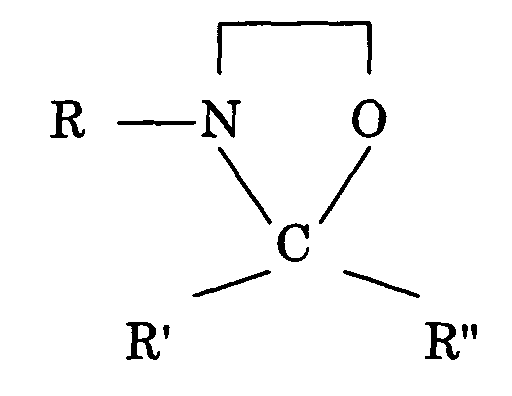
- Oxazolidines, particularly oxazolidines having the following formula:
wherein, preferably R is an ethyl group, R' is a methyl group and R" is 3-(methyl)-butane.
Surprisingly, it has been found that said compounds provide a fast
removal of water from the chamber. The fast removal of the water is
advantageous in case the chamber comprises components which are sensitive
to water and/or may be harmed or damaged by water. Besides, that fast
removal of water is desired in case the chamber has to be brought to a certain
vacuum level. The present method for removing water from a chamber can be
applied in different fields, for example vacuum technology, semiconductor
manufacturing technology, lithography, deposition, etching, and/or any other
field where such water removal is desired.
Embodiments of the invention will now be described, by way of example
only, with reference to the accompanying schematic drawings in which
corresponding reference symbols indicate corresponding parts, and in which:
EMBODIMENTS
Figure 1 schematically depicts a lithographic apparatus which
comprises:
- an illumination system (illuminator) IL for providing a projection
beam PB of radiation (e.g. UV or EUV radiation).
- a first support structure (e.g. a mask table) MT for supporting
patterning means (e.g. a mask) MA and connected to first positioning means
PM for accurately positioning the patterning means with respect to item PL;
- a substrate table (e.g. a wafer table) WT for holding a substrate
(e.g. a resist-coated wafer) W and connected to second positioning means PW
for accurately positioning the substrate with respect to item PL; and
- a projection system (e.g. a reflective projection lens) PL for
imaging a pattern imparted to the projection beam PB by patterning means
MA onto a target portion C (e.g. comprising one or more dies) of the substrate
W.
As here depicted, the apparatus is of a reflective type (e.g. employing a
reflective mask or a programmable mirror array of a type as referred to above).
Alternatively, the apparatus may be of a transmissive type (e.g. employing a
transmissive mask).
The illuminator IL receives a beam of radiation from a radiation source
SO. The source and the lithographic apparatus may be separate entities, for
example when the source is a plasma discharge source. In such cases, the
source is not considered to form part of the lithographic apparatus and the
radiation beam is generally passed from the source SO to the illuminator IL
with the aid of a radiation collector comprising for example suitable collecting
mirrors and/or a spectral purity filter. In other cases the source may be
integral part of the apparatus, for example when the source is a mercury lamp.
The source SO and the illuminator IL, may be referred to as a radiation
system.
The illuminator IL may comprise adjusting means for adjusting the
angular intensity distribution of the beam. Generally, at least the outer and/or
inner radial extent (commonly referred to as σ-outer and σ-inner, respectively)
of the intensity distribution in a pupil plane of the illuminator can be adjusted.
The illuminator provides a conditioned beam of radiation, referred to as the
projection beam PB, having a desired uniformity and intensity distribution in
its cross-section.
The projection beam PB is incident on the mask MA, which is held on
the mask table MT. Being reflected by the mask MA, the projection beam PB
passes through the lens PL, which focuses the beam onto a target portion C of
the substrate W. With the aid of the second positioning means PW and position
sensor IF2 (e.g. an interferometric device), the substrate table WT can be
moved accurately, e.g. so as to position different target portions C in the path
of the beam PB. Similarly, the first positioning means PM and position sensor
IF1 can be used to accurately position the mask MA with respect to the path of
the beam PB, e.g. after mechanical retrieval from a mask library, or during a
scan. In general, movement of the object tables MT and WT will be realized
with the aid of a long-stroke module (coarse positioning) and a short-stroke
module (fine positioning), which form part of the positioning means PM and
PW. However, in the case of a stepper (as opposed to a scanner) the mask table
MT may be connected to a short stroke actuator only, or may be fixed. Mask
MA and substrate W may be aligned using mask alignment marks M1, M2 and
substrate alignment marks P1, P2.
The depicted apparatus can be used in the following preferred modes:
Combinations and/or variations on the above described modes of use or
entirely different modes of use may also be employed.
Figure 2 shows an embodiment of a lithographic apparatus according to
the present invention. The apparatus shown in fig. 2 is arranged for carrying
out a device manufacturing method as described above concerning the
embodiment shown in fig. 1. To this aim, the apparatus of fig. 2 comprises an
illumination system for providing a projection beam PB of radiation, a mask
support structure MT for supporting a mask MA, a substrate table WT for
holding a substrate W, as well as a projection system PL for projecting the
patterned beam PB onto a target portion C of the substrate W. For clarity, said
illumination system is not shown in fig. 2.
The embodiment of fig. 2 comprises a main vacuum chamber 1 within
which said mask support structure MT, mask MA, projection system PL and
substrate table WT are located. The apparatus comprises at least one vacuum
pump 4 which is coupled to the main vacuum chamber 1 for creating and
maintaining a certain vacuum level therein. The main chamber 1 comprises
baking means 100, which are known from the art and may comprise for
example one or more electrical heating wires 100 extending through or along
the wall 9 of the chamber. The baking means are arranged for heating the wall
9 of the chamber 1 to remove compounds which are adsorbed thereto. In fig. 2,
only an exterior part of the baking means 100 is depicted. The baking means
100 can further be arranged, for instance, for baking at least part of the
content of the chamber 1.
The present embodiment further comprises a mask handler 10 and a
substrate handler 11 for handling masks MA and substrates W respectively.
Each handler 10, 11 can be constructed in various ways, for example
comprising on or more actuators, robot arms, guiding means and such. The
mask handler 10 is positioned in a mask load-lock chamber 5. The substrate
handler 11 is situated in a substrate load-lock chamber 6. The handlers 10, 11
are partly movable into and out of the main vacuum chamber 1 for
transporting masks MA and substrates W thereto and therefrom, particularly
for replacing masks MA and substrates W. The load- locks 5, 6 and handlers 10,
11 as such are known from practice. Particularly, each load- lock 5, 6 is a
vacuum chamber which can be entered from the main vacuum chamber 1, as
well as from an environment of the apparatus via respective, hermetically
closable entrances. The load- lock chambers 5, 6 can also be coupled to one or
more vacuum pumps for providing suitable vacuum levels therein. These lock-lock
pumps are not shown in fig. 2.
According to one aspect of the invention, the apparatus comprises at
least one supply arrangement 2, 2', 3, 3' which is arranged to supply at least
one chemical reagent to said vacuum chambers 1, 5, 6. Said reagent is
chemically active with water. The embodiment of fig. 2 comprises two supply
arrangements. The first supply arrangement comprises a first reservoir 2
which contains said at least one chemical reagent. The first reservoir 2 can be
brought in fluid communication with the main vacuum chamber 1 and the
mask load-lock chamber 5 via respective supply lines 3. Each of these supply
lines 3 comprises a flow regulator for regulating the amount of fluid which
flows there through towards the respective vacuum chamber 1, 5. The second
supply arrangement comprises a second reservoir 2' which contains said at
least one chemical reagent. The second reservoir 2' is coupled to said substrate
load-lock 6 via a supply line 3', which also comprises a flow regulator.
In the present embodiment, each fluid reservoir (2, 2') is located outside
the vacuum chambers 1, 5, 6. However, one or more reservoirs can also be
integrated or located inside one or more of the vacuum chambers 1, 5, 6. The
location of the reservoirs 2, 2' depends amongst others on the nature of the at
least one chemical reagent and the conditions in the vacuum chambers 1, 5, 6.
For example, said chemical reagent may be solid and/or liquid when it is
contained in the reservoirs 2, 2'. Then, the chemical reagent can be sublimated
or evaporated into a vacuum chamber 1, 5, 6, provided that the nature of the
chemical reagent and vacuum chamber conditions as the chamber pressure
and temperature are suitable thereto. On the other hand, the chemical reagent
can be at least partially gaseous, and for instance pressurized, when contained
in the reservoir 2, 2'.
Said chemical reagent serves to remove water from the vacuum
chambers 1, 5, 6. To this aim, said chemical reagent is preferably active with
water for increasing the desorption of water, particularly such that the water
can be more easily desorbed and/or removed from parts of the apparatus, such
as the vacuum chamber walls 9, a reticle MA, projection means PL and/or from
substrates W. For example, the chemical reagent can be active with water for
breaking O-H bonds of water molecules which are adsorbed to other water
molecules and/or to parts of the apparatus and/or to substrates W. Herein, the
breaking of intermolecular O-H bonds between water molecules is particularly
advantageous to remove relatively thick multilayers of adsorbed water from
the apparatus. Furthermore, said chemical reagent can be active with water,
for instance, to form at least one reaction product with water, wherein said
reaction product has a lower adsorption energy than water, particularly
concerning adsorption to parts of the apparatus, such as the vacuum chamber
walls 9, a reticle MA, projection means PL and/or substrates W. Further, said
reaction product preferably has weaker intermolecular forces than water.
Besides, said chemical reagent can form for example at least one complex with
water, wherein said complex has a lower adsorption energy and/or weaker
intermolecular forces than water. According to an advantageous embodiment,
said chemical reagent decomposes water at least partly into volatile
substances. Volatile substances can be pumped from the vacuum chambers 1,
5, 6 by the at least one vacuum pump 4 of the apparatus. The term 'volatile
substances' can be construed as meaning any atoms, molecules an/or other
substances which are in a gaseous phase in the respective chamber at the
pressure and temperature thereof. Particularly, said volatile substances have a
higher vapour pressure than water.
The at least one chemical reagent can comprise for example at least one
of the compounds selected from the group consisting of:
- silicon containing compounds;
- halogen containing compounds; and
- hydrocarbon compounds, which hydrocarbon compounds optionally contain
one or more oxygen atoms and/or one or more nitrogen atoms. Particularly,
said hydrocarbons compounds are CxHyOzNw compounds (z, w>=0) and may
optionally comprise, for example, one or more silicon and/or halogen atoms.
Examples of the at least one reagent are: silane compounds, trimethyl-chloro-silane,
dimethyl-dichloro-silane; monomethyl-trichloro-silane,
tetrachloro-silane, dichloro-propane, dibromo-propane, nitrosyl-chloride,
carbonyl-chloride (phosgene), carbonyl-fluoride, diborane, chlorine, fluorine,
fluorine mixed with carbon monoxide, thionyl-bromide, iodomethyl-propane,
acetyl-chloride, acetone-dimethyl-acetal, ethanol, hexane, oxyhalogen
compounds. Examples of the oxyhalogen compounds have the formulas POCl3,
VOCl3, SOCl2, SO2CL2, CH3SO2CL, SeOCl2, and CrO2Cl2.
Further examples of the at least one reagent are the following,
numbered (1) to (10):
wherein, preferably R is an ethyl group, R' is a methyl group and R" is 3-(methyl)-butane
(commercial available, for example as Zoldine MS-Plus of the
Angus Chemical Company or
Incozol 2 of Industrial Copolymers Limited).
Examples (1)-(10) can be used, for instance, in a lithographic
manufacturing method and/or any other method for removing water from one
or more chambers. In the examples (1)-(10), at least some of said R, R', R", R1
and R2 groups are preferably alkyl groups. More preferably, at least some of
said R, R', R", R1 and R2 are methyl, ethyl, propyl and/or butyl groups, as has
been described above in some of the examples. Besides, each said R, R', R", R1
and R2 can also be for example an other group, for instance an aryl group.
Preferably, the at least one chemical reagent as such is also a volatile
compound, so that it can be removed from the vacuum system by said at least
one vacuum pump 4.
The embodiment of fig. 2 further comprises at least one UV light source
7 which is arranged to illuminate at least part of an inner surface 9 of the
main vacuum chamber 1 and/or its content with UV light, preferably deep UV
(DUV) light with a wavelength of less than about 400 nm. Note, that this light
source 7 is additional to the above-mentioned radiation source and
illuminating system IL for generating said projection beam PB. One or more
such additional light sources 7 can also be provided in the load- lock chambers
5,6.
During use, the at least one chemical reagent is supplied to one or more
of said vacuum chambers 1, 5, 6 by said supply arrangements 2, 3, 2', 3' for
removing water from the vacuum chambers. The chemical reagent may for
example lower the desorption energy of water, decompose water into volatile
compounds and/or form volatile complexes with water, so that water can be
removed from the vacuum chambers 1, 5, 6 with ease by the at least one
vacuum pump 4.
Fig. 3 shows simulation results of an example of the present invention,
wherein a vacuum chamber is pumped down to a certain vacuum level by one
or more vacuum pumps. Fig. 3 is a graph, wherein line U, comprising symbols
'⋄', depicts the chamber pressure against time for pumping results which are
obtained when no reagent is supplied to the vacuum chamber. In fig. 3, line L,
comprising symbols 'Δ', shows the results of the chamber pressure when a
chemical reagent was supplied to the chamber for removing water thereform.
From fig. 3, it follows that the start of the pumpdown of curve L is later than
the pumpdown of curve U. The pumpdown start of curve L is delayed due to
the supply of the reagent to the vacuum chamber before the start of the
pumpdown and/or during the pumpdown. From fig.3 it clearly follows, that
curve L falls below curve U very fast because of the removal of water from the
chamber caused by the reagent. The application of the reagent clearly leads to
a much faster pumping down of the vacuum chamber.
The interiors of the vacuum chambers 1, 5, 6 are preferably irradiated
by said UV light sources 7 to remove water therefrom, for instance by speeding
up the chemical reaction between said chemical reagent and water and/or by
breaking intermolecular O-H water adsorption bonds. The water can be
removed from the vacuum chambers when the apparatus is at a certain
desired operating temperature, for instance room temperature or thereabouts.
Consequently, no or only a mild baking out procedure can be applied to obtain
or maintain a desired vacuum level in the apparatus, so that damage to and/or
misalignment of heat sensitive apparatus components can be prevented. Said
mild baking out procedure can be applied by using the baking means 100 (see
fig. 2). During such mild baking, the wall of the main chamber 1 is heated to a
certain relatively low baking temperature, preferably a baking temperature of
about 100° C or less, particularly about 60° C or less, to promote the removal of
substances which are adsorbed thereto. More preferably, said temperature is
about room temperature.
The fast and efficient removal of the water from the apparatus prevents
degradation of water sensitive apparatus parts, such as mirrors, the reticle or
other parts. To avoid degradation of water sensitive parts, the partial pressure
of the water in the main vacuum chamber 1 is preferably reduced to less than
circa 10-5 mbar, more preferably less than 10-7 mbar or even less than 10-9
mbar. Besides, the at least one vacuum chamber can be pumped down
relatively fast from atmospheric pressure to a desired vacuum level by the use
of said reagent.
The method according to the present invention can be carried out in
several ways. For instance, said at least one chemical reagent can be supplied
to said vacuum chamber 1 before and/or after the patterned beam of radiation
PB is projected onto the substrate W. Each substrate may bring some residual
water into the vacuum system when it is transported therein, via the substrate
load-lock 6. Then, it is advantageous to supply the chemical reagent to the
substrate load-lock chamber 6 before the substrate W is transported to the
main vacuum chamber by the substrate handler 11, so that said residual water
can be removed from the substrate W in the load-lock chamber 6. In the same
manner, said chemical reagent can be supplied to the main vacuum chamber 1
when a substrate W is transported therein and/or has just been installed onto
the substrate table WT, again to remove said residual water. After the
substrate-bound water has been removed and/or decomposed by the chemical
reagent and has been pumped from the system, the substrate W can be
illuminated by the radiation beam PB, as described above with reference to fig.
1. When the above describes substrate illumination process has ended, said
chemical reagent can again be supplied to one or more of the vacuum chambers
of the apparatus 1, 5, 6 for water removal and/or decomposition.
Besides, said chemical reagent can be used to chemically remove water
from the apparatus and reticles MA during and after transport of the reticles
MA via the reticle load-lock 5. To that aim, said reagent can be supplied to the
reticle load-lock chamber 5 and/or to the main vacuum chamber 1, using the
respective reagent supply arrangement 2, 3.
During use, the amount of chemical reagent which is to be supplied to
the vacuum chambers 1, 5, 6 can be controlled precisely using the flow
controllers of said supply lines 3, 3'. The apparatus preferably comprises a
control unit, not shown, for example a micro-controller and/or computer, for
regulating the flow of the reagent during the use of the apparatus. A relatively
large amount of reagent can -for instance- be supplied to the main vacuum
chamber 1 when no lithographic process is carried out therein. Then, the
excess amount of supplied reagent can be pumped from the main chamber 1 by
the vacuum pumps 4.
According to a further embodiment, said chemical reagent is supplied to
said main vacuum chamber 1 at least during part of the period when the
patterned beam of radiation PB is projected onto the substrate W. In this case,
preferably a relatively low amount of reagent is continuously or periodically
supplied to the main chamber 1, so that the vacuum level of the main chamber
1 is substantially not or only slightly affected thereby. This has the advantage,
that water can also be desorbed, removed and/or decomposed in the main
chamber 1 when said substrate illumination process is carried out therein.
Again, the at least one vacuum pump 4 can pump any excess reagent from the
main chamber 1.
Besides, when the main vacuum chamber 1, the substrate load-lock
chamber 6 and/or reticle load-lock chamber 5 have been brought to
substantially atmospheric pressure and need to be pumped down to a certain
vacuum level again, the respective chambers 1, 5, 6 can be flushed with a large
amount of said chemical reagent for quick water removal.
While specific embodiments of the invention have been described above,
it will be appreciated that the invention may be practiced otherwise than as
described, within the scope of the claims. The description is not intended to
limit the invention.
Said chemical reagent can comprise one or more suitable chemicals.
Preferably, the reagent and said reaction products do not react with materials
used in the lithographic apparatus, whilst they have a relatively low
adsorption energy with the materials used in the apparatus. Furthermore, one
or more catalysts may be used in combination with the at least one reagent to
remove the water from the chamber, particularly depending on the nature of
the reagent.
Furthermore, the term 'a relative low adsorption energy' can be
understood as a low energy of absorption of the relevant compound to said
vacuum chamber wall 9, other apparatus parts and/or substrates, relative to
energy of adsorption of water to that vacuum chamber wall 9, other apparatus
parts and/or substrates.
The apparatus may comprise one or more chambers, for instance said
main chamber 1, one or more substrate handling chambers, one or more reticle
handling chambers, a numerical aperture stop handling chamber and/or other
chambers. Then, said chemical reagent can be supplied to one or more of said
chambers. Besides, one or more of said chambers can be irradiated by UV light
to remove water therefrom.
During use, each chamber 1, 5, 6 may be at a certain vacuum pressure
or at atmospheric pressure, depending on the kind of process which is or has to
be carried out therein, for instance depending on the type of radiation used in
case a lithographic process is or has to be carried out in the chamber. For
example, the pressure in the apparatus may be a substantially atmospheric
pressure or a higher pressure during the lithographic manufacturing process.
Then, the at least one chemical reagent can be supplied to the at least one
chamber of the apparatus for the removal of water therefrom, providing the
above-mentioned advantages.
Different parts of the lithographic apparatus can be located in the same
or in several chambers. For instance, the substrate holder WT and mask
support structure MT can be located in the same chamber or in separate
chambers.
Further, for the case that different chemical reagents are used, each
reagent supplier may comprise for example one or more reservoirs containing
these reagents.