EP1528263A1 - A crane - Google Patents
A crane Download PDFInfo
- Publication number
- EP1528263A1 EP1528263A1 EP03024718A EP03024718A EP1528263A1 EP 1528263 A1 EP1528263 A1 EP 1528263A1 EP 03024718 A EP03024718 A EP 03024718A EP 03024718 A EP03024718 A EP 03024718A EP 1528263 A1 EP1528263 A1 EP 1528263A1
- Authority
- EP
- European Patent Office
- Prior art keywords
- conduit
- piston rod
- cylinder
- pressure
- side chamber
- Prior art date
- Legal status (The legal status is an assumption and is not a legal conclusion. Google has not performed a legal analysis and makes no representation as to the accuracy of the status listed.)
- Withdrawn
Links
Images

Classifications
-
- F—MECHANICAL ENGINEERING; LIGHTING; HEATING; WEAPONS; BLASTING
- F15—FLUID-PRESSURE ACTUATORS; HYDRAULICS OR PNEUMATICS IN GENERAL
- F15B—SYSTEMS ACTING BY MEANS OF FLUIDS IN GENERAL; FLUID-PRESSURE ACTUATORS, e.g. SERVOMOTORS; DETAILS OF FLUID-PRESSURE SYSTEMS, NOT OTHERWISE PROVIDED FOR
- F15B11/00—Servomotor systems without provision for follow-up action ; Circuits therefor
- F15B11/02—Systems essentially incorporating special features for controlling the speed or the actuating force of an output member
- F15B11/024—Systems essentially incorporating special features for controlling the speed or the actuating force of an output member by means of differential connection of the servomotor lines, e.g. regenerative circuits
-
- B—PERFORMING OPERATIONS; TRANSPORTING
- B66—HOISTING; LIFTING; HAULING
- B66C—CRANES; LOAD-ENGAGING ELEMENTS OR DEVICES FOR CRANES, CAPSTANS, WINCHES, OR TACKLES
- B66C13/00—Other constructional features or details
- B66C13/18—Control systems or devices
-
- B—PERFORMING OPERATIONS; TRANSPORTING
- B66—HOISTING; LIFTING; HAULING
- B66C—CRANES; LOAD-ENGAGING ELEMENTS OR DEVICES FOR CRANES, CAPSTANS, WINCHES, OR TACKLES
- B66C23/00—Cranes comprising essentially a beam, boom, or triangular structure acting as a cantilever and mounted for translatory of swinging movements in vertical or horizontal planes or a combination of such movements, e.g. jib-cranes, derricks, tower cranes
- B66C23/54—Cranes comprising essentially a beam, boom, or triangular structure acting as a cantilever and mounted for translatory of swinging movements in vertical or horizontal planes or a combination of such movements, e.g. jib-cranes, derricks, tower cranes with pneumatic or hydraulic motors, e.g. for actuating jib-cranes on tractors
-
- F—MECHANICAL ENGINEERING; LIGHTING; HEATING; WEAPONS; BLASTING
- F15—FLUID-PRESSURE ACTUATORS; HYDRAULICS OR PNEUMATICS IN GENERAL
- F15B—SYSTEMS ACTING BY MEANS OF FLUIDS IN GENERAL; FLUID-PRESSURE ACTUATORS, e.g. SERVOMOTORS; DETAILS OF FLUID-PRESSURE SYSTEMS, NOT OTHERWISE PROVIDED FOR
- F15B11/00—Servomotor systems without provision for follow-up action ; Circuits therefor
- F15B11/02—Systems essentially incorporating special features for controlling the speed or the actuating force of an output member
- F15B11/024—Systems essentially incorporating special features for controlling the speed or the actuating force of an output member by means of differential connection of the servomotor lines, e.g. regenerative circuits
- F15B2011/0243—Systems essentially incorporating special features for controlling the speed or the actuating force of an output member by means of differential connection of the servomotor lines, e.g. regenerative circuits the regenerative circuit being activated or deactivated automatically
-
- F—MECHANICAL ENGINEERING; LIGHTING; HEATING; WEAPONS; BLASTING
- F15—FLUID-PRESSURE ACTUATORS; HYDRAULICS OR PNEUMATICS IN GENERAL
- F15B—SYSTEMS ACTING BY MEANS OF FLUIDS IN GENERAL; FLUID-PRESSURE ACTUATORS, e.g. SERVOMOTORS; DETAILS OF FLUID-PRESSURE SYSTEMS, NOT OTHERWISE PROVIDED FOR
- F15B2211/00—Circuits for servomotor systems
- F15B2211/30—Directional control
- F15B2211/305—Directional control characterised by the type of valves
- F15B2211/30525—Directional control valves, e.g. 4/3-directional control valve
-
- F—MECHANICAL ENGINEERING; LIGHTING; HEATING; WEAPONS; BLASTING
- F15—FLUID-PRESSURE ACTUATORS; HYDRAULICS OR PNEUMATICS IN GENERAL
- F15B—SYSTEMS ACTING BY MEANS OF FLUIDS IN GENERAL; FLUID-PRESSURE ACTUATORS, e.g. SERVOMOTORS; DETAILS OF FLUID-PRESSURE SYSTEMS, NOT OTHERWISE PROVIDED FOR
- F15B2211/00—Circuits for servomotor systems
- F15B2211/30—Directional control
- F15B2211/305—Directional control characterised by the type of valves
- F15B2211/3056—Assemblies of multiple valves
- F15B2211/30565—Assemblies of multiple valves having multiple valves for a single output member, e.g. for creating higher valve function by use of multiple valves like two 2/2-valves replacing a 5/3-valve
- F15B2211/3058—Assemblies of multiple valves having multiple valves for a single output member, e.g. for creating higher valve function by use of multiple valves like two 2/2-valves replacing a 5/3-valve having additional valves for interconnecting the fluid chambers of a double-acting actuator, e.g. for regeneration mode or for floating mode
-
- F—MECHANICAL ENGINEERING; LIGHTING; HEATING; WEAPONS; BLASTING
- F15—FLUID-PRESSURE ACTUATORS; HYDRAULICS OR PNEUMATICS IN GENERAL
- F15B—SYSTEMS ACTING BY MEANS OF FLUIDS IN GENERAL; FLUID-PRESSURE ACTUATORS, e.g. SERVOMOTORS; DETAILS OF FLUID-PRESSURE SYSTEMS, NOT OTHERWISE PROVIDED FOR
- F15B2211/00—Circuits for servomotor systems
- F15B2211/50—Pressure control
- F15B2211/505—Pressure control characterised by the type of pressure control means
- F15B2211/50509—Pressure control characterised by the type of pressure control means the pressure control means controlling a pressure upstream of the pressure control means
- F15B2211/50518—Pressure control characterised by the type of pressure control means the pressure control means controlling a pressure upstream of the pressure control means using pressure relief valves
-
- F—MECHANICAL ENGINEERING; LIGHTING; HEATING; WEAPONS; BLASTING
- F15—FLUID-PRESSURE ACTUATORS; HYDRAULICS OR PNEUMATICS IN GENERAL
- F15B—SYSTEMS ACTING BY MEANS OF FLUIDS IN GENERAL; FLUID-PRESSURE ACTUATORS, e.g. SERVOMOTORS; DETAILS OF FLUID-PRESSURE SYSTEMS, NOT OTHERWISE PROVIDED FOR
- F15B2211/00—Circuits for servomotor systems
- F15B2211/50—Pressure control
- F15B2211/505—Pressure control characterised by the type of pressure control means
- F15B2211/50563—Pressure control characterised by the type of pressure control means the pressure control means controlling a differential pressure
- F15B2211/50581—Pressure control characterised by the type of pressure control means the pressure control means controlling a differential pressure using counterbalance valves
-
- F—MECHANICAL ENGINEERING; LIGHTING; HEATING; WEAPONS; BLASTING
- F15—FLUID-PRESSURE ACTUATORS; HYDRAULICS OR PNEUMATICS IN GENERAL
- F15B—SYSTEMS ACTING BY MEANS OF FLUIDS IN GENERAL; FLUID-PRESSURE ACTUATORS, e.g. SERVOMOTORS; DETAILS OF FLUID-PRESSURE SYSTEMS, NOT OTHERWISE PROVIDED FOR
- F15B2211/00—Circuits for servomotor systems
- F15B2211/50—Pressure control
- F15B2211/515—Pressure control characterised by the connections of the pressure control means in the circuit
- F15B2211/5153—Pressure control characterised by the connections of the pressure control means in the circuit being connected to an output member and a directional control valve
-
- F—MECHANICAL ENGINEERING; LIGHTING; HEATING; WEAPONS; BLASTING
- F15—FLUID-PRESSURE ACTUATORS; HYDRAULICS OR PNEUMATICS IN GENERAL
- F15B—SYSTEMS ACTING BY MEANS OF FLUIDS IN GENERAL; FLUID-PRESSURE ACTUATORS, e.g. SERVOMOTORS; DETAILS OF FLUID-PRESSURE SYSTEMS, NOT OTHERWISE PROVIDED FOR
- F15B2211/00—Circuits for servomotor systems
- F15B2211/50—Pressure control
- F15B2211/55—Pressure control for limiting a pressure up to a maximum pressure, e.g. by using a pressure relief valve
-
- F—MECHANICAL ENGINEERING; LIGHTING; HEATING; WEAPONS; BLASTING
- F15—FLUID-PRESSURE ACTUATORS; HYDRAULICS OR PNEUMATICS IN GENERAL
- F15B—SYSTEMS ACTING BY MEANS OF FLUIDS IN GENERAL; FLUID-PRESSURE ACTUATORS, e.g. SERVOMOTORS; DETAILS OF FLUID-PRESSURE SYSTEMS, NOT OTHERWISE PROVIDED FOR
- F15B2211/00—Circuits for servomotor systems
- F15B2211/70—Output members, e.g. hydraulic motors or cylinders or control therefor
- F15B2211/705—Output members, e.g. hydraulic motors or cylinders or control therefor characterised by the type of output members or actuators
- F15B2211/7051—Linear output members
- F15B2211/7057—Linear output members being of the telescopic type
-
- F—MECHANICAL ENGINEERING; LIGHTING; HEATING; WEAPONS; BLASTING
- F15—FLUID-PRESSURE ACTUATORS; HYDRAULICS OR PNEUMATICS IN GENERAL
- F15B—SYSTEMS ACTING BY MEANS OF FLUIDS IN GENERAL; FLUID-PRESSURE ACTUATORS, e.g. SERVOMOTORS; DETAILS OF FLUID-PRESSURE SYSTEMS, NOT OTHERWISE PROVIDED FOR
- F15B2211/00—Circuits for servomotor systems
- F15B2211/70—Output members, e.g. hydraulic motors or cylinders or control therefor
- F15B2211/71—Multiple output members, e.g. multiple hydraulic motors or cylinders
- F15B2211/7114—Multiple output members, e.g. multiple hydraulic motors or cylinders with direct connection between the chambers of different actuators
- F15B2211/7128—Multiple output members, e.g. multiple hydraulic motors or cylinders with direct connection between the chambers of different actuators the chambers being connected in parallel
-
- F—MECHANICAL ENGINEERING; LIGHTING; HEATING; WEAPONS; BLASTING
- F15—FLUID-PRESSURE ACTUATORS; HYDRAULICS OR PNEUMATICS IN GENERAL
- F15B—SYSTEMS ACTING BY MEANS OF FLUIDS IN GENERAL; FLUID-PRESSURE ACTUATORS, e.g. SERVOMOTORS; DETAILS OF FLUID-PRESSURE SYSTEMS, NOT OTHERWISE PROVIDED FOR
- F15B2211/00—Circuits for servomotor systems
- F15B2211/70—Output members, e.g. hydraulic motors or cylinders or control therefor
- F15B2211/75—Control of speed of the output member
Definitions
- the present invention relates to a crane, comprising two interconnected beams and, for the displacement of each beam respectively, at least two cylinder/piston units each of which comprises a piston rod that is displaceable in a cylinder and a piston that is connected to the piston rod and separates the cylinder chamber in a cylinder side chamber and a piston rod side chamber, said cylinder being provided with an opening in the cylinder gable in order to permit a displacement of the piston rod out of and into the cylinder, a first conduit for conducting a pressure fluid from a pressure fluid source to the cylinder side chambers, and a second conduit for conducting pressure fluid from the piston rod side chambers to a pressure fluid reservoir that has a lower pressure than the pressure fluid source, and a third conduit for regenerative conduction of pressure fluid from the piston rod side chamber of the first hydraulic unit to the cylinder side chamber thereof,
- the invention is applicable to all types of cranes, but is particularly applicable to cranes for lifting piece goods, presenting a considerable overhang when in an extended position.
- the invention will therefore be described by way of example with reference to such an application.
- hydraulic units according to the invention can be utilized for the purpose of imparting swinging movements as well as longitudinal movements of any beam that forms a part of the crane.
- the invention is particularly suitable for cranes that comprise a plurality of beams that are arranged in a telescopic way.
- the beams are displaced in relation to each other by means of a plurality of hydraulic cylinder/piston units, one for each arm.
- the invention is particularly related to cranes by which said units are successively arranged, or bus-type connected, in the meaning that a first one thereof is more adjacent the pressure source and the reservoir in terms of fluid flow distance than the second one, and that there is a conduit between each pair of units for the purpose of conducting pressure fluid from the piston rod side chamber of one of the units to the piston rod side chamber of the other unit.
- a common conduit for the regeneration flow of oil is used for all units.
- This regeneration conduit may be arranged as a single conduit connected, in one end, to a conduit leading from a pressure fluid source to the cylinder side chambers of the cylinder-piston units, and, in the other end, to a conduit leading from the piston rod side chambers of said units to a reservoir of lower pressure than the pressure source.
- the regeneration conduit is arranged downstream a first cylinder-piston unit, downstream being referred to as between said unit and the pressure source and reservoir respectively.
- the object of the present invention is achieved by means of a crane as initially defined, characterised in that it comprises a fourth conduit for regenerative conduction of pressure fluid from the piston rod side chamber of the second hydraulic unit to the cylinder side chamber thereof.
- a crane as initially defined, characterised in that it comprises a fourth conduit for regenerative conduction of pressure fluid from the piston rod side chamber of the second hydraulic unit to the cylinder side chamber thereof.
- the regenerative flow does not need to go via all the (downstream) piston rod side chambers that are arranged in series before being regenerated via the third conduit and first conduit to the cylinder side chambers.
- the invention includes such an embodiment.
- the crane is further characterised in that it comprises at least one valve member arranged for permitting a regenerative flow through the fourth conduit under condition that the pressure in the first conduit is above a pre-determined absolute pressure level and that there is a flow of pressure fluid in the second conduit in a direction from the piston rod side chamber of the second hydraulic unit towards the reservoir.
- the crane according to the invention comprises a means for detecting whether the pressure in the first conduit is above said pre-determined level, and a means for detecting the fluid flow direction in the second conduit, these means being connected to the at least one valve member for the purpose of controlling the operation thereof.
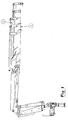
- Fig. 1 shows a crane according to the invention.
- the crane comprises a plurality of beams 1 that are telescopically arranged in relation to each other in order to permit adjustment of its length from a shortest length, in which the beams are inserted into each other, to a maximum length when they are fully extended.
- the crane comprises a plurality of hydraulic units 2 for driving the beams 1 in way known per se.
- each hydraulic unit 2 comprises a cylinder 3 and a piston 4 with a piston rod 5.
- the piston divides the cylinder chamber into a cylinder side chamber 6 and a piston rod side chamber 7.
- the piston area is larger on the cylinder side than on the piston rod side.
- the piston rod 5 is arranged to perform a reciprocating movement through an opening 8 in a gable 9 of the cylinder 3 for its operation.
- the crane For the actuation of the hydraulic unit the crane comprises a first conduit 10 that connects the cylinder side chambers 6 of the hydraulic units 2 with a pressure fluid source 11 via a direction valve 12 in a way known per se.
- the cylinder side chambers 6 may be regarded as connected in parallel with each other in relation to the source 11.
- the fluid pressure in the pressure fluid source may, for example, be 28 MPa.
- the crane also comprises a second conduit 13 that connects the piston rod side chamber 7 of a first one of the hydraulic units 2 with a low pressure reservoir 14 for drainage of pressure fluid from the chamber 7 to the reservoir 14.
- the fluid pressure in the reservoir 14 may, as here, be equal to atmospheric pressure.
- the third conduit 15 is arranged for controlled regenerative pressure fluid flow from the piston rod side chambers 7 to the cylinder side chambers 6 during extension of the crane.
- the crane according to the invention comprises a pressure delimiting member 16 in the second conduit 13.
- a pilot-controlled valve 17 in the second conduit 13.
- valve 17 Upon activation of valve 17, it will permit a flow throughthe second conduit 13 towards the reservoir.
- the regenerative flow through the third conduit 15 is stopped, or at least substantially reduced, as valve 17 is actuated in order to permit a flow of fluid from the piston rod side chamber 7 to the reservoir 14.
- full extension of the hydraulic unit 2 in question can be attained with a remaining high or even further increased pressure on the cylinder side and a reduced, but still substantial, pressure on the piston rod side thanks to the pressure delimiting member 16.
- the pressure delimiting member 16 should comprise a counter pressure valve and may comprise any kind of throttle or constriction. It only opens for passage when the pressure in the piston rod side chamber exceeds a given value, in this example 24 MPa.
- the pressure delimiting member 16 is arranged so as to delimit the pressure in the piston rod side chamber 7 to approximately 24 MPa while the pressure in the cylinder side chamber reaches approximately 28 MPa during the continued piston rod displacement without aid of regenerative flow.
- Pilot-controlled valve 17 in the second conduit 13 is controlled based on the pressure value measured or detected by the measuring means 18, 19, by means pressure fluid connection from the measuring means 18, 19 to the valve 17 upon the presence of a given pressure in the first conduit 10. It should be emphasized that the term measurement as used in this context also may comprise simple indication of one specific pressure level, and not necessarily a literal measurement. Once a specific pressure acts on the measuring means 18,19, an hydraulic pressure may be applied to the pilot-controlled valve, for example via a leak conduit from the measuring means 18,19.
- Said measuring means 18,19 comprises a conduit 18 connected to the first conduit 10 and the reservoir 14, via the second conduit, and a (spring-loaded non-return) valve 19.
- a piloting impulse of pressure fluid is conducted via a further conduit, here indicated with a broken line 21 from the piloting valve 19 to the pilot-controlled valve 17 for the actuation thereof.
- a constriction 31 is arranged downstream valve 19 in said conduit 18 in order to, together with valve 19, determine the pressure at which the pilot-controlled valve 17 is to open.
- valve 23 in the third conduit 15 for regenerative flow.
- the regeneration valve 23 is actuated by the pressure of the first conduit 10, with which it is connected via a pilot flow conduit 20.
- Said pilot controlled valve 23 upon actuation thereof, opens for regenerative flow of pressure fluid from piston rod side chamber 7 to cylinder side chamber 6.
- a non-return valve that prevents flow in the opposite direction, that is from cylinder side chamber 6 to piston rod side chamber 7.
- Valve 23 defines a means for breakingor interrupting the regenerative operation.
- the third conduit 15 could be directly connected with, for example, the direction valve 12, and that the latter could then be equipped with a slide valve that would take the place and function of the regeneration valve 23 and the non-return valve in series therewith.
- the individual piston rod side chambers 7 are connected in bus-type in a series via a plurality of conduits 13" each of which is provided between two consecutive piston rod side chambers in the row of hydraulic units 2. However, they could also be connected in a connection of a star-type. Said intermediate conduits 13" can be regarded as parts of the second conduit 13 or as sub-conduits of the second conduit 13.
- a piston rod side chamber 7 of a first hydraulic unit is connected via the second conduit 13 to the low pressure reservoir 14.
- Each cylinder-piston unit is arranged for the purpose of displacing or swinging a respective beam of the crane. Except the first unit in such a series of units, which is connected to a crane base in one end and a first beam in the other end, each unit is connected to two adjacent beams for interrelated movement thereof.
- a fourth conduit 24 for regenerative conduction of pressure fluid from the piston rod side chamber 7 of one of the hydraulic units 2 to the cylinder side chamber 6 thereof.
- a first end of the fourth conduit 24 is connected to the first conduit 10 and a second end thereof is connected to the intermediate conduit 13" that leads form the piston rod side chamber 7 of one of the units 2 to the piston rod side chamber 7 of the other one of said units 2.
- the crane comprises a first valve member 25 arranged for permitting a regenerative flow through the fourth conduit under condition that the pressure in the first conduit is above a pre-determined absolute pressure level.
- a second valve member 26 arranged for permitting a regenerative flow through the fourth conduit under condition that there is a flow of pressure fluid in the second conduit 13 in a direction from the cylinder side chamber 6 of the second hydraulic unit 2 towards the reservoir 14.
- This pressure sensing means is incorporated in the first valve member 25 since the latter is designed as a spring loaded valve, the spring of which is under action of the pressure in the first conduit 10, the valve 25 being arranged for opening when the force generated by the pressure fluid in the first conduit 10 and acting on the spring exceeds the spring force.
- the second valve member 26 is a pilot-controlled valve member controlled by the means 27 for detecting the flow direction in the intermediate second conduit 13".
- the hydraulic connection 28 defines a means for sensing the pressure fall over the means 27 for detecting the flow direction.
- the means 27 for detecting the flow direction in the intermediate second conduit 13" comprises a spring loaded valve, the spring of which is under action of the pressure in the intermediate second conduit upstream said one way valve 27 as seen in flow direction from the second unit 2 towards the reservoir 14.
- the valve 27 is opened when the force generated by the pressure fluid in the second conduit and acting on the spring of the valve 27 exceeds the spring force. A fluid pressure pulse from valve 27 will then flow via connection 28 and affect the opening of second valve member 26.
- the crane comprises a number of elements the function of which are important for a reliable and effective operation of the crane. Accordingly there is a non-return valve 29 provided in parallel with the pressure delimiting member 16 in the second conduit, for allowing a flow of pressure fluid from the reservoir 14 towards the piston rod chambers 7 without throttling caused by the pressure delimiting member 16.
- a non-return valve 30 is arranged in a corresponding way and for a corresponding purpose, in parallel with the flow direction detecting means 27.
- non-return valves that normally permit the regenerative flow towards the cylinder side chamber 6 but prevent a flow in the opposite direction, are a natural part of any embodiment of the invention, in order to further improve the operation of the crane.
Landscapes
- Engineering & Computer Science (AREA)
- Mechanical Engineering (AREA)
- Automation & Control Theory (AREA)
- Physics & Mathematics (AREA)
- Fluid Mechanics (AREA)
- General Engineering & Computer Science (AREA)
- Fluid-Pressure Circuits (AREA)
- Jib Cranes (AREA)
- Control And Safety Of Cranes (AREA)
Abstract
A crane, comprising two interconnected beams and, for the displacement of each beam respectively, at least two cylinder/piston units (2), each of which comprises a piston rod (5) that is displaceable in a cylinder (3) and a piston (4) that is connected to the piston rod (5) and separates the cylinder chamber in a cylinder side chamber (6) and a piston rod side chamber (7), said cylinder (3) being provided with an opening (8) in the cylinder gable (9) in order to permit a displacement of the piston rod (5) out of and into the cylinder, a first conduit (10) for conducting a pressure fluid from a pressure fluid source (11) to the cylinder side chambers (6), and a second conduit (13) for conducting pressure fluid from the piston rod side chambers (7) to a pressure fluid reservoir (14) that has a lower pressure than the pressure fluid source (11), and a third conduit (15) for regenerative conduction of pressure fluid from the piston rod side chamber (7) of a first hydraulic unit (2) to the cylinder side chamber (6) thereof The crane comprises a fourth conduit (24) for regenerative conduction of pressure fluid from the piston rod side chamber (7) of a second hydraulic unit (2) to the cylinder side chamber (6) thereof.
Description
- The present invention relates to a crane, comprising two interconnected beams and, for the displacement of each beam respectively, at least two cylinder/piston units each of which comprises a piston rod that is displaceable in a cylinder and a piston that is connected to the piston rod and separates the cylinder chamber in a cylinder side chamber and a piston rod side chamber, said cylinder being provided with an opening in the cylinder gable in order to permit a displacement of the piston rod out of and into the cylinder, a first conduit for conducting a pressure fluid from a pressure fluid source to the cylinder side chambers, and a second conduit for conducting pressure fluid from the piston rod side chambers to a pressure fluid reservoir that has a lower pressure than the pressure fluid source, and a third conduit for regenerative conduction of pressure fluid from the piston rod side chamber of the first hydraulic unit to the cylinder side chamber thereof,
- The invention is applicable to all types of cranes, but is particularly applicable to cranes for lifting piece goods, presenting a considerable overhang when in an extended position. The invention will therefore be described by way of example with reference to such an application.
- It should be understood that the hydraulic units according to the invention can be utilized for the purpose of imparting swinging movements as well as longitudinal movements of any beam that forms a part of the crane.
- Even though not necessary restricted to such an embodiment, the invention is particularly suitable for cranes that comprise a plurality of beams that are arranged in a telescopic way. In order to elongate or extend such a crane, the beams are displaced in relation to each other by means of a plurality of hydraulic cylinder/piston units, one for each arm.
- The invention is particularly related to cranes by which said units are successively arranged, or bus-type connected, in the meaning that a first one thereof is more adjacent the pressure source and the reservoir in terms of fluid flow distance than the second one, and that there is a conduit between each pair of units for the purpose of conducting pressure fluid from the piston rod side chamber of one of the units to the piston rod side chamber of the other unit.
- Along with an increasing need of longer overhangs on piece goods cranes, the time and power needed for the extension of the crane to its maximum overhang has become an important issue in connection to the design of such cranes. Generally, there is a need of reducing the time that is required for attaining maximum crane length.
- Different ways of reducing the maximum power required for attaining maximum overhang have been proposed. Some prior art uses sequential extension of the arms. However, in sequentially controlled cranes, there is an important flow resistance for the pressure fluid that is used. A sequentially controlled crane will require less power and lower maximum load on the individual cylinder/piston unit than a non-sequentially controlled crane, but will be slower.
- It has also been proposed to lower the extension resistance of the beams by means of lubrication thereof. However, lubricated beams often result in lubrication oil leaking out to the environment. In some applications, such leakage cannot be accepted and is therefore of disadvantage.
- Accordingly, there is a strive to present a crane the extension of which is not performed sequentially and which does not require any lubrication of vital beam parts in order to attain maximum overhang.
- In order to increase the extension speed of the crane it has been proposed to use regenerative conduction of the pressure fluid, normally oil, from the piston rod side chambers to the cylinder side chambers during the extension operation of the crane. Thereby, less oil has to be conducted from a pressurised oil source all the way to the cylinder side chambers, while, simultaneously the pressure of the oil that exits from the piston rod side chambers is taken advantage of for the purpose of filling the cylinder side chambers instead of only being conducted to a low pressure tank or reservoir.
- In the case when the crane comprises a plurality of beams and a corresponding number of cylinder/piston units, a common conduit for the regeneration flow of oil is used for all units. This regeneration conduit may be arranged as a single conduit connected, in one end, to a conduit leading from a pressure fluid source to the cylinder side chambers of the cylinder-piston units, and, in the other end, to a conduit leading from the piston rod side chambers of said units to a reservoir of lower pressure than the pressure source. Preferably, the regeneration conduit is arranged downstream a first cylinder-piston unit, downstream being referred to as between said unit and the pressure source and reservoir respectively.
- It is an object of the present invention to present a crane as initially defined that, during extension of the hydraulic units of the crane, takes advantage of regenerative operation and minimises the effect of pressure loss during the regeneration and maximises the speed with which the beams of the crane are extended or swung.
- It is a further object of the invention to present a crane and a method as initially defined that is readily applicable to existingcrane constructions and that is advantageous because of its relative constructional simplicity and operation reliability.
- The object of the present invention is achieved by means of a crane as initially defined, characterised in that it comprises a fourth conduit for regenerative conduction of pressure fluid from the piston rod side chamber of the second hydraulic unit to the cylinder side chamber thereof. It should be understood that, among a plurality of such units, the first and second unit do not necessarily need to be located adjacent to each other. It might even be preferred that there is at least one further unit physically located between said units.
- If the cylinder-piston units are connected to each other in a bus type connection in which the second conduit comprises a plurality of sub conduits or intermediate conduits leading from one piston rod side chamber to another in a series, the regenerative flow does not need to go via all the (downstream) piston rod side chambers that are arranged in series before being regenerated via the third conduit and first conduit to the cylinder side chambers. The invention includes such an embodiment.
- According to a preferred embodiment, the crane is further characterised in that it comprises at least one valve member arranged for permitting a regenerative flow through the fourth conduit under condition that the pressure in the first conduit is above a pre-determined absolute pressure level and that there is a flow of pressure fluid in the second conduit in a direction from the piston rod side chamber of the second hydraulic unit towards the reservoir. Thereby, unwanted opening of the fourth conduit when there is no extension of the crane ordered can be avoided.
- Preferably, the crane according to the invention comprises a means for detecting whether the pressure in the first conduit is above said pre-determined level, and a means for detecting the fluid flow direction in the second conduit, these means being connected to the at least one valve member for the purpose of controlling the operation thereof.
- Further preferred embodiments of the invention are presented in dependent claims 4-10.
- Further advantages and features of the invention will be presented in the following detailed description thereof.
- The invention will now be described by way of example with reference to the annexed drawings, on which.
- Fig. 1 is a schematic view of a crane on which the invention might be applied,
- Fig. 2 is a hydraulic scheme showing essential parts of the invention according to a first embodiment.
-
- Fig. 1 shows a crane according to the invention. The crane comprises a plurality of
beams 1 that are telescopically arranged in relation to each other in order to permit adjustment of its length from a shortest length, in which the beams are inserted into each other, to a maximum length when they are fully extended. The crane comprises a plurality ofhydraulic units 2 for driving thebeams 1 in way known per se. According to fig. 2 eachhydraulic unit 2 comprises a cylinder 3 and apiston 4 with apiston rod 5. the piston divides the cylinder chamber into a cylinder side chamber 6 and a piston rod side chamber 7. The piston area is larger on the cylinder side than on the piston rod side. Thepiston rod 5 is arranged to perform a reciprocating movement through an opening 8 in agable 9 of the cylinder 3 for its operation. - For the actuation of the hydraulic unit the crane comprises a
first conduit 10 that connects the cylinder side chambers 6 of thehydraulic units 2 with apressure fluid source 11 via adirection valve 12 in a way known per se. The cylinder side chambers 6 may be regarded as connected in parallel with each other in relation to thesource 11. The fluid pressure in the pressure fluid source may, for example, be 28 MPa. - The crane also comprises a
second conduit 13 that connects the piston rod side chamber 7 of a first one of thehydraulic units 2 with alow pressure reservoir 14 for drainage of pressure fluid from the chamber 7 to thereservoir 14. The fluid pressure in thereservoir 14 may, as here, be equal to atmospheric pressure. - There is also provided a
third conduit 15 that in one end is connected to thefirst conduit 10 and in another end is connected thesecond conduit 13. Thethird conduit 15 is arranged for controlled regenerative pressure fluid flow from the piston rod side chambers 7 to the cylinder side chambers 6 during extension of the crane. - According to fig. 2 the crane according to the invention comprises a
pressure delimiting member 16 in thesecond conduit 13. There is also provided a pilot-controlledvalve 17 in thesecond conduit 13. Upon activation ofvalve 17, it will permit a flow throughthesecond conduit 13 towards the reservoir. During extension of the crane under regenerative operation, the regenerative flow through thethird conduit 15 is stopped, or at least substantially reduced, asvalve 17 is actuated in order to permit a flow of fluid from the piston rod side chamber 7 to thereservoir 14. Thereby, full extension of thehydraulic unit 2 in question can be attained with a remaining high or even further increased pressure on the cylinder side and a reduced, but still substantial, pressure on the piston rod side thanks to thepressure delimiting member 16. Thepressure delimiting member 16 should comprise a counter pressure valve and may comprise any kind of throttle or constriction. It only opens for passage when the pressure in the piston rod side chamber exceeds a given value, in this example 24 MPa. Here, thepressure delimiting member 16 is arranged so as to delimit the pressure in the piston rod side chamber 7 to approximately 24 MPa while the pressure in the cylinder side chamber reaches approximately 28 MPa during the continued piston rod displacement without aid of regenerative flow. - It should be mentioned that, as an alternative to the above arrangement, there might be provided a pressure delimiting member in the
first conduit 10 between thedirection valve 12 and the cylinder side chamber 6, instead of having a pressure delimiting member corresponding tomember 16 in thesecond conduit 13. Then, such a pressure delimiting member is actuated at the moment when the pressure on the cylinder side has reached a value by which the pilot controlledvalve 17 is opened for passage and regenerative operation is ended. Thereby the pressure in the cylinder side chamber 6 is reduced to a given value while the pressure in the piston rod side chamber is reduced to generally the same pressure as in thereservoir 14 through activation ofvalve 17. - Preferably, there is provided a
means first conduit 10 orthird conduit 15 during regenerative operation. - Pilot-controlled
valve 17 in thesecond conduit 13 is controlled based on the pressure value measured or detected by the measuring means 18, 19, by means pressure fluid connection from the measuring means 18, 19 to thevalve 17 upon the presence of a given pressure in thefirst conduit 10. It should be emphasized that the term measurement as used in this context also may comprise simple indication of one specific pressure level, and not necessarily a literal measurement. Once a specific pressure acts on the measuring means 18,19, an hydraulic pressure may be applied to the pilot-controlled valve, for example via a leak conduit from the measuring means 18,19. - Said measuring means 18,19 comprises a
conduit 18 connected to thefirst conduit 10 and thereservoir 14, via the second conduit, and a (spring-loaded non-return)valve 19. When the pressure fall over the (non-return)valve 19, that closes for flow towards thereservoir 14, reaches or exceeds a threshold value, a piloting impulse of pressure fluid is conducted via a further conduit, here indicated with abroken line 21 from the pilotingvalve 19 to the pilot-controlledvalve 17 for the actuation thereof. Aconstriction 31 is arrangeddownstream valve 19 in saidconduit 18 in order to, together withvalve 19, determine the pressure at which the pilot-controlledvalve 17 is to open. - In the embodiment shown in fig. 2, there is also provided a spring loaded, pilot-controlled
valve 23 in thethird conduit 15 for regenerative flow. Theregeneration valve 23 is actuated by the pressure of thefirst conduit 10, with which it is connected via apilot flow conduit 20. Said pilot controlledvalve 23, upon actuation thereof, opens for regenerative flow of pressure fluid from piston rod side chamber 7 to cylinder side chamber 6. In series with pilot-controlledvalve 23 in thethird conduit 15 there is provided a non-return valve that prevents flow in the opposite direction, that is from cylinder side chamber 6 to piston rod side chamber 7.Valve 23 defines a means for breakingor interrupting the regenerative operation. It should be understood that, as an alternative, thethird conduit 15 could be directly connected with, for example, thedirection valve 12, and that the latter could then be equipped with a slide valve that would take the place and function of theregeneration valve 23 and the non-return valve in series therewith. - As indicated in fig. 2, the individual piston rod side chambers 7 are connected in bus-type in a series via a plurality of
conduits 13" each of which is provided between two consecutive piston rod side chambers in the row ofhydraulic units 2. However, they could also be connected in a connection of a star-type. Saidintermediate conduits 13" can be regarded as parts of thesecond conduit 13 or as sub-conduits of thesecond conduit 13. A piston rod side chamber 7 of a first hydraulic unit is connected via thesecond conduit 13 to thelow pressure reservoir 14. Each cylinder-piston unit is arranged for the purpose of displacing or swinging a respective beam of the crane. Except the first unit in such a series of units, which is connected to a crane base in one end and a first beam in the other end, each unit is connected to two adjacent beams for interrelated movement thereof. - Between two consecutive
hydraulic units 2, there is afourth conduit 24 for regenerative conduction of pressure fluid from the piston rod side chamber 7 of one of thehydraulic units 2 to the cylinder side chamber 6 thereof. Here, a first end of thefourth conduit 24 is connected to thefirst conduit 10 and a second end thereof is connected to theintermediate conduit 13" that leads form the piston rod side chamber 7 of one of theunits 2 to the piston rod side chamber 7 of the other one of saidunits 2. - The crane comprises a
first valve member 25 arranged for permitting a regenerative flow through the fourth conduit under condition that the pressure in the first conduit is above a pre-determined absolute pressure level. There is also asecond valve member 26 arranged for permitting a regenerative flow through the fourth conduit under condition that there is a flow of pressure fluid in thesecond conduit 13 in a direction from the cylinder side chamber 6 of the secondhydraulic unit 2 towards thereservoir 14. - There is also provided a means for detecting whether the pressure in the
first conduit 10 is above said pre-determined level. This pressure sensing means is incorporated in thefirst valve member 25 since the latter is designed as a spring loaded valve, the spring of which is under action of the pressure in thefirst conduit 10, thevalve 25 being arranged for opening when the force generated by the pressure fluid in thefirst conduit 10 and acting on the spring exceeds the spring force. - There is also provided a
means 27 for detecting the fluid flow direction in the intermediatesecond conduit 13". Thesecond valve member 26 is a pilot-controlled valve member controlled by themeans 27 for detecting the flow direction in the intermediatesecond conduit 13". - There is a
hydraulic connection 28 between thesecond valve member 26 and themeans 27 for detecting the flow direction in the intermediatesecond conduit 13". Thehydraulic connection 28 defines a means for sensing the pressure fall over themeans 27 for detecting the flow direction. - The means 27 for detecting the flow direction in the intermediate
second conduit 13" comprises a spring loaded valve, the spring of which is under action of the pressure in the intermediate second conduit upstream said oneway valve 27 as seen in flow direction from thesecond unit 2 towards thereservoir 14. Thevalve 27 is opened when the force generated by the pressure fluid in the second conduit and acting on the spring of thevalve 27 exceeds the spring force. A fluid pressure pulse fromvalve 27 will then flow viaconnection 28 and affect the opening ofsecond valve member 26. - Apart from the elements that have been described above, the crane comprises a number of elements the function of which are important for a reliable and effective operation of the crane. Accordingly there is a
non-return valve 29 provided in parallel with thepressure delimiting member 16 in the second conduit, for allowing a flow of pressure fluid from thereservoir 14 towards the piston rod chambers 7 without throttling caused by thepressure delimiting member 16. Anon-return valve 30 is arranged in a corresponding way and for a corresponding purpose, in parallel with the flowdirection detecting means 27. - It should be understood that non-return valves that normally permit the regenerative flow towards the cylinder side chamber 6 but prevent a flow in the opposite direction, are a natural part of any embodiment of the invention, in order to further improve the operation of the crane.
- It should be realised that the above presentation of the invention has been made by way of example, and that alternative embodiments will be obvious for a man skilled in the art without going beyond the scope of protection as claimed in the annexed patent claims supported by the description and the annexed drawings.
Claims (9)
- A crane, comprisingcharacterized in that it comprises a fourth conduit (24) for regenerative conduction of pressure fluid from the piston rod side chamber (7) of a second hydraulic unit (2) to the cylinder side chamber (6) thereof.two interconnected beams and, for the displacement of each beam respectively, at least two cylinder/piston units (2), each of which comprises a piston rod (5) that is displaceable in a cylinder (3) and a piston (4) that is connected to the piston rod (5) and separates the cylinder chamber in a cylinder side chamber (6) and a piston rod side chamber (7), said cylinder (3) being provided with an opening (8) in the cylinder gable (9) in order to permit a displacement of the piston rod (5) out of and into the cylinder,a first conduit (10) for conducting a pressure fluid from a pressure fluid source (11) to the cylinder side chambers (6), anda second conduit (13) for conducting pressure fluid from the piston rod side chambers (7) to a pressure fluid reservoir (14) that has a lower pressure than the pressure fluid source (11), anda third conduit for regenerative conduction of pressure fluid from the piston rod side chamber (7) of a first hydraulic unit (2) to the cylinder side chamber (6) thereof,
- A crane according to claim 1, characterised in that it comprises at least one valve member (25, 26) arranged for permitting a regenerative flow through the fourth conduit (24) under condition that the pressure in the first conduit is above a pre-determined absolute pressure level and that there is a flow of pressure fluid in the second conduit (13) in a direction from the piston rod side chamber (7) of the second hydraulic unit (2) towards the reservoir (14).
- A crane according to claim 2, characterised in that it comprises a means for detecting whether the pressure in the first conduit (10) is above said pre-determined level, and a means (27) for detecting the fluid flow direction in the second conduit (13").
- A crane according to claim 3, characterised in that said at least one valve member (25, 26) is operatively connected to said detecting means (27), and controlled on basis of the detected absolute pressure in first conduit (10) and the detected flow direction in the second conduit (13").
- A crane according to any one of claims 1-4, characterised in that the second conduit (13) comprises a first part (13') leading from the piston rod side chamber (7) of the first unit to the reservoir (14) and a second part (13") leading from the piston rod side chamber (7) of the second unit (2) to the piston rod side chamber (7) of the first unit (2), and that the means (27) for detecting the flow direction in the second conduit (13) detects the flow direction in said second part(13") of the second conduit (13).
- A crane according to any one of claims 3-5, characterised in that said at least one valve member (26) is a pilot-controlled valve member controlled by the detecting means (27) for detecting the flow direction in the second conduit.
- A crane according to any one of claims 3-6, characterised in that it comprises a hydraulic connection between the at least one valve member (26) and the means(27) for detecting the flow direction in the second conduit (13).
- A crane according to any one of claims 3-7, characterised in that the at least one valve member (25) comprises a spring loaded valve, the spring of which is under action of the pressure in the first cmduit (10), the valve being arranged for opening when the force generated by the pressure fluid in the first conduit (10) and acting on the spring exceeds the spring force.
- A crane according to any one of claims 3-8, characterised in that the means (27) for detecting the flow direction in the second conduit (13") comprises a spring loaded valve (27), the spring of which is under action of the pressure in the second conduit (13") upstream said one way valve as seen in flow direction from the second unit towards the reservoir (14), and that said valve (27) is opened when the force generated by the pressure fluid in the second conduit (13") on the spring exceeds the spring force.
Priority Applications (1)
| Application Number | Priority Date | Filing Date | Title |
|---|---|---|---|
| EP03024718A EP1528263A1 (en) | 2003-10-29 | 2003-10-29 | A crane |
Applications Claiming Priority (1)
| Application Number | Priority Date | Filing Date | Title |
|---|---|---|---|
| EP03024718A EP1528263A1 (en) | 2003-10-29 | 2003-10-29 | A crane |
Publications (1)
| Publication Number | Publication Date |
|---|---|
| EP1528263A1 true EP1528263A1 (en) | 2005-05-04 |
Family
ID=34400478
Family Applications (1)
| Application Number | Title | Priority Date | Filing Date |
|---|---|---|---|
| EP03024718A Withdrawn EP1528263A1 (en) | 2003-10-29 | 2003-10-29 | A crane |
Country Status (1)
| Country | Link |
|---|---|
| EP (1) | EP1528263A1 (en) |
Cited By (1)
| Publication number | Priority date | Publication date | Assignee | Title |
|---|---|---|---|---|
| WO2011156829A1 (en) * | 2010-06-17 | 2011-12-22 | Palfinger Ag | Vehicle crane |
Citations (3)
| Publication number | Priority date | Publication date | Assignee | Title |
|---|---|---|---|---|
| US4125974A (en) * | 1977-07-08 | 1978-11-21 | Harnischfeger Corporation | Control system for telescopic boom |
| GB2159605A (en) * | 1984-06-01 | 1985-12-04 | Ming Chuan Shieh | Regenerating reflux valve |
| DE3801007A1 (en) * | 1988-01-15 | 1989-07-27 | Joh Tirre Ohg Maschf | Rapid-motion control system for a push cylinder, in particular for a push cylinder of a loading crane |
-
2003
- 2003-10-29 EP EP03024718A patent/EP1528263A1/en not_active Withdrawn
Patent Citations (3)
| Publication number | Priority date | Publication date | Assignee | Title |
|---|---|---|---|---|
| US4125974A (en) * | 1977-07-08 | 1978-11-21 | Harnischfeger Corporation | Control system for telescopic boom |
| GB2159605A (en) * | 1984-06-01 | 1985-12-04 | Ming Chuan Shieh | Regenerating reflux valve |
| DE3801007A1 (en) * | 1988-01-15 | 1989-07-27 | Joh Tirre Ohg Maschf | Rapid-motion control system for a push cylinder, in particular for a push cylinder of a loading crane |
Cited By (2)
| Publication number | Priority date | Publication date | Assignee | Title |
|---|---|---|---|---|
| WO2011156829A1 (en) * | 2010-06-17 | 2011-12-22 | Palfinger Ag | Vehicle crane |
| US8875912B2 (en) | 2010-06-17 | 2014-11-04 | Palfinger Ag | Vehicle crane |
Similar Documents
| Publication | Publication Date | Title |
|---|---|---|
| US7752842B2 (en) | Circuit for controlling a double-action hydraulic drive cylinder | |
| US7243591B2 (en) | Hydraulic valve arrangement | |
| EP2652341B1 (en) | Hydraulic system with return pressure control | |
| US20110017310A1 (en) | Fluid valve arrangement | |
| JP7098334B2 (en) | Attenuating shuttle valve | |
| KR930006269A (en) | Hydraulics for Construction Equipment | |
| NZ200515A (en) | Hydraulic control system with pilot controlled meter-in valve | |
| US20070044650A1 (en) | Valve having a hysteretic filtered actuation command | |
| JP2008267460A (en) | Hydraulic actuator speed controller | |
| EP1707529B1 (en) | Multistaged telescopic boom | |
| EP1628018A1 (en) | Anti-saturation directional control valve composed of two or more sections with pressure selector compensators | |
| CN101275592B (en) | Hydropneumatic pressure transmission device | |
| CN102979778A (en) | Three-position six-way reversing valve, hydraulic control system and engineering vehicle | |
| EP2365226B1 (en) | Hydraulic system | |
| US6256986B1 (en) | Hydrostatic drive system | |
| EP3228580A1 (en) | A control device of an actuator | |
| JPH07101042B2 (en) | Hydraulic control device | |
| JP2013513770A (en) | Valve unit for driving load section | |
| EP1528262A1 (en) | A crane and a method for controlling a crane | |
| US11820187B2 (en) | Hydropneumatic suspension system for vehicles | |
| GB2212220A (en) | Hydraulic control block | |
| EP1895168A1 (en) | Valve arrangement | |
| WO2017061647A1 (en) | Control system of construction equipment | |
| EP4299918A1 (en) | A hydraulic system | |
| JPH0341706B2 (en) |
Legal Events
| Date | Code | Title | Description |
|---|---|---|---|
| PUAI | Public reference made under article 153(3) epc to a published international application that has entered the european phase |
Free format text: ORIGINAL CODE: 0009012 |
|
| AK | Designated contracting states |
Kind code of ref document: A1 Designated state(s): AT BE BG CH CY CZ DE DK EE ES FI FR GB GR HU IE IT LI LU MC NL PT RO SE SI SK TR |
|
| AX | Request for extension of the european patent |
Extension state: AL LT LV MK |
|
| AKX | Designation fees paid | ||
| REG | Reference to a national code |
Ref country code: DE Ref legal event code: 8566 |
|
| STAA | Information on the status of an ep patent application or granted ep patent |
Free format text: STATUS: THE APPLICATION IS DEEMED TO BE WITHDRAWN |
|
| 18D | Application deemed to be withdrawn |
Effective date: 20051105 |