EP1527935A1 - Method for verifying predetermined bearing preload of differential assembly module - Google Patents
Method for verifying predetermined bearing preload of differential assembly module Download PDFInfo
- Publication number
- EP1527935A1 EP1527935A1 EP04105390A EP04105390A EP1527935A1 EP 1527935 A1 EP1527935 A1 EP 1527935A1 EP 04105390 A EP04105390 A EP 04105390A EP 04105390 A EP04105390 A EP 04105390A EP 1527935 A1 EP1527935 A1 EP 1527935A1
- Authority
- EP
- European Patent Office
- Prior art keywords
- differential
- mounting
- carrier frame
- frame member
- support beam
- Prior art date
- Legal status (The legal status is an assumption and is not a legal conclusion. Google has not performed a legal analysis and makes no representation as to the accuracy of the status listed.)
- Withdrawn
Links
- 230000036316 preload Effects 0.000 title claims abstract description 49
- 238000000034 method Methods 0.000 title claims abstract description 40
- 230000000295 complement effect Effects 0.000 claims description 18
- 230000000712 assembly Effects 0.000 description 6
- 238000000429 assembly Methods 0.000 description 6
- 230000007246 mechanism Effects 0.000 description 5
- 239000002184 metal Substances 0.000 description 5
- 230000008569 process Effects 0.000 description 4
- 238000005266 casting Methods 0.000 description 2
- 239000012467 final product Substances 0.000 description 2
- 238000005242 forging Methods 0.000 description 2
- 238000012986 modification Methods 0.000 description 2
- 230000004048 modification Effects 0.000 description 2
- WTEVQBCEXWBHNA-YFHOEESVSA-N neral Chemical compound CC(C)=CCC\C(C)=C/C=O WTEVQBCEXWBHNA-YFHOEESVSA-N 0.000 description 2
- 238000003466 welding Methods 0.000 description 2
- WTEVQBCEXWBHNA-UHFFFAOYSA-N Citral Natural products CC(C)=CCCC(C)=CC=O WTEVQBCEXWBHNA-UHFFFAOYSA-N 0.000 description 1
- STECJAGHUSJQJN-USLFZFAMSA-N LSM-4015 Chemical compound C1([C@@H](CO)C(=O)OC2C[C@@H]3N([C@H](C2)[C@@H]2[C@H]3O2)C)=CC=CC=C1 STECJAGHUSJQJN-USLFZFAMSA-N 0.000 description 1
- 229910000831 Steel Inorganic materials 0.000 description 1
- 238000004026 adhesive bonding Methods 0.000 description 1
- WTEVQBCEXWBHNA-JXMROGBWSA-N citral A Natural products CC(C)=CCC\C(C)=C\C=O WTEVQBCEXWBHNA-JXMROGBWSA-N 0.000 description 1
- 238000002485 combustion reaction Methods 0.000 description 1
- 230000006835 compression Effects 0.000 description 1
- 238000007906 compression Methods 0.000 description 1
- 238000011109 contamination Methods 0.000 description 1
- 230000008878 coupling Effects 0.000 description 1
- 238000010168 coupling process Methods 0.000 description 1
- 238000005859 coupling reaction Methods 0.000 description 1
- 230000007423 decrease Effects 0.000 description 1
- 230000002708 enhancing effect Effects 0.000 description 1
- 239000000314 lubricant Substances 0.000 description 1
- 238000003754 machining Methods 0.000 description 1
- 238000004519 manufacturing process Methods 0.000 description 1
- 239000007769 metal material Substances 0.000 description 1
- 230000007935 neutral effect Effects 0.000 description 1
- 239000002245 particle Substances 0.000 description 1
- 230000002093 peripheral effect Effects 0.000 description 1
- 229920000136 polysorbate Polymers 0.000 description 1
- 230000002028 premature Effects 0.000 description 1
- 239000010959 steel Substances 0.000 description 1
Images



Classifications
-
- B—PERFORMING OPERATIONS; TRANSPORTING
- B60—VEHICLES IN GENERAL
- B60K—ARRANGEMENT OR MOUNTING OF PROPULSION UNITS OR OF TRANSMISSIONS IN VEHICLES; ARRANGEMENT OR MOUNTING OF PLURAL DIVERSE PRIME-MOVERS IN VEHICLES; AUXILIARY DRIVES FOR VEHICLES; INSTRUMENTATION OR DASHBOARDS FOR VEHICLES; ARRANGEMENTS IN CONNECTION WITH COOLING, AIR INTAKE, GAS EXHAUST OR FUEL SUPPLY OF PROPULSION UNITS IN VEHICLES
- B60K17/00—Arrangement or mounting of transmissions in vehicles
- B60K17/04—Arrangement or mounting of transmissions in vehicles characterised by arrangement, location or kind of gearing
- B60K17/16—Arrangement or mounting of transmissions in vehicles characterised by arrangement, location or kind of gearing of differential gearing
- B60K17/165—Arrangement or mounting of transmissions in vehicles characterised by arrangement, location or kind of gearing of differential gearing provided between independent half axles
-
- F—MECHANICAL ENGINEERING; LIGHTING; HEATING; WEAPONS; BLASTING
- F16—ENGINEERING ELEMENTS AND UNITS; GENERAL MEASURES FOR PRODUCING AND MAINTAINING EFFECTIVE FUNCTIONING OF MACHINES OR INSTALLATIONS; THERMAL INSULATION IN GENERAL
- F16H—GEARING
- F16H48/00—Differential gearings
- F16H48/06—Differential gearings with gears having orbital motion
- F16H48/08—Differential gearings with gears having orbital motion comprising bevel gears
-
- B—PERFORMING OPERATIONS; TRANSPORTING
- B60—VEHICLES IN GENERAL
- B60G—VEHICLE SUSPENSION ARRANGEMENTS
- B60G2206/00—Indexing codes related to the manufacturing of suspensions: constructional features, the materials used, procedures or tools
- B60G2206/01—Constructional features of suspension elements, e.g. arms, dampers, springs
- B60G2206/014—Constructional features of suspension elements, e.g. arms, dampers, springs with reinforcing nerves or branches
-
- B—PERFORMING OPERATIONS; TRANSPORTING
- B60—VEHICLES IN GENERAL
- B60G—VEHICLE SUSPENSION ARRANGEMENTS
- B60G2206/00—Indexing codes related to the manufacturing of suspensions: constructional features, the materials used, procedures or tools
- B60G2206/01—Constructional features of suspension elements, e.g. arms, dampers, springs
- B60G2206/30—Constructional features of rigid axles
- B60G2206/31—Straight axle
-
- F—MECHANICAL ENGINEERING; LIGHTING; HEATING; WEAPONS; BLASTING
- F16—ENGINEERING ELEMENTS AND UNITS; GENERAL MEASURES FOR PRODUCING AND MAINTAINING EFFECTIVE FUNCTIONING OF MACHINES OR INSTALLATIONS; THERMAL INSULATION IN GENERAL
- F16H—GEARING
- F16H48/00—Differential gearings
- F16H48/06—Differential gearings with gears having orbital motion
- F16H48/08—Differential gearings with gears having orbital motion comprising bevel gears
- F16H2048/082—Differential gearings with gears having orbital motion comprising bevel gears characterised by the arrangement of output shafts
-
- F—MECHANICAL ENGINEERING; LIGHTING; HEATING; WEAPONS; BLASTING
- F16—ENGINEERING ELEMENTS AND UNITS; GENERAL MEASURES FOR PRODUCING AND MAINTAINING EFFECTIVE FUNCTIONING OF MACHINES OR INSTALLATIONS; THERMAL INSULATION IN GENERAL
- F16H—GEARING
- F16H48/00—Differential gearings
- F16H48/38—Constructional details
- F16H2048/382—Methods for manufacturing differential gearings
-
- Y—GENERAL TAGGING OF NEW TECHNOLOGICAL DEVELOPMENTS; GENERAL TAGGING OF CROSS-SECTIONAL TECHNOLOGIES SPANNING OVER SEVERAL SECTIONS OF THE IPC; TECHNICAL SUBJECTS COVERED BY FORMER USPC CROSS-REFERENCE ART COLLECTIONS [XRACs] AND DIGESTS
- Y10—TECHNICAL SUBJECTS COVERED BY FORMER USPC
- Y10T—TECHNICAL SUBJECTS COVERED BY FORMER US CLASSIFICATION
- Y10T29/00—Metal working
- Y10T29/49—Method of mechanical manufacture
- Y10T29/49636—Process for making bearing or component thereof
- Y10T29/497—Pre-usage process, e.g., preloading, aligning
-
- Y—GENERAL TAGGING OF NEW TECHNOLOGICAL DEVELOPMENTS; GENERAL TAGGING OF CROSS-SECTIONAL TECHNOLOGIES SPANNING OVER SEVERAL SECTIONS OF THE IPC; TECHNICAL SUBJECTS COVERED BY FORMER USPC CROSS-REFERENCE ART COLLECTIONS [XRACs] AND DIGESTS
- Y10—TECHNICAL SUBJECTS COVERED BY FORMER USPC
- Y10T—TECHNICAL SUBJECTS COVERED BY FORMER US CLASSIFICATION
- Y10T29/00—Metal working
- Y10T29/49—Method of mechanical manufacture
- Y10T29/49764—Method of mechanical manufacture with testing or indicating
-
- Y—GENERAL TAGGING OF NEW TECHNOLOGICAL DEVELOPMENTS; GENERAL TAGGING OF CROSS-SECTIONAL TECHNOLOGIES SPANNING OVER SEVERAL SECTIONS OF THE IPC; TECHNICAL SUBJECTS COVERED BY FORMER USPC CROSS-REFERENCE ART COLLECTIONS [XRACs] AND DIGESTS
- Y10—TECHNICAL SUBJECTS COVERED BY FORMER USPC
- Y10T—TECHNICAL SUBJECTS COVERED BY FORMER US CLASSIFICATION
- Y10T29/00—Metal working
- Y10T29/49—Method of mechanical manufacture
- Y10T29/49764—Method of mechanical manufacture with testing or indicating
- Y10T29/49771—Quantitative measuring or gauging
- Y10T29/49776—Pressure, force, or weight determining
-
- Y—GENERAL TAGGING OF NEW TECHNOLOGICAL DEVELOPMENTS; GENERAL TAGGING OF CROSS-SECTIONAL TECHNOLOGIES SPANNING OVER SEVERAL SECTIONS OF THE IPC; TECHNICAL SUBJECTS COVERED BY FORMER USPC CROSS-REFERENCE ART COLLECTIONS [XRACs] AND DIGESTS
- Y10—TECHNICAL SUBJECTS COVERED BY FORMER USPC
- Y10T—TECHNICAL SUBJECTS COVERED BY FORMER US CLASSIFICATION
- Y10T29/00—Metal working
- Y10T29/49—Method of mechanical manufacture
- Y10T29/49764—Method of mechanical manufacture with testing or indicating
- Y10T29/49778—Method of mechanical manufacture with testing or indicating with aligning, guiding, or instruction
-
- Y—GENERAL TAGGING OF NEW TECHNOLOGICAL DEVELOPMENTS; GENERAL TAGGING OF CROSS-SECTIONAL TECHNOLOGIES SPANNING OVER SEVERAL SECTIONS OF THE IPC; TECHNICAL SUBJECTS COVERED BY FORMER USPC CROSS-REFERENCE ART COLLECTIONS [XRACs] AND DIGESTS
- Y10—TECHNICAL SUBJECTS COVERED BY FORMER USPC
- Y10T—TECHNICAL SUBJECTS COVERED BY FORMER US CLASSIFICATION
- Y10T29/00—Metal working
- Y10T29/49—Method of mechanical manufacture
- Y10T29/49764—Method of mechanical manufacture with testing or indicating
- Y10T29/49778—Method of mechanical manufacture with testing or indicating with aligning, guiding, or instruction
- Y10T29/4978—Assisting assembly or disassembly
-
- Y—GENERAL TAGGING OF NEW TECHNOLOGICAL DEVELOPMENTS; GENERAL TAGGING OF CROSS-SECTIONAL TECHNOLOGIES SPANNING OVER SEVERAL SECTIONS OF THE IPC; TECHNICAL SUBJECTS COVERED BY FORMER USPC CROSS-REFERENCE ART COLLECTIONS [XRACs] AND DIGESTS
- Y10—TECHNICAL SUBJECTS COVERED BY FORMER USPC
- Y10T—TECHNICAL SUBJECTS COVERED BY FORMER US CLASSIFICATION
- Y10T74/00—Machine element or mechanism
- Y10T74/21—Elements
- Y10T74/2186—Gear casings
- Y10T74/2188—Axle and torque tubes
Definitions
- the present invention relates to drive axle assemblies for motor vehicles and methods for assembling the same in ge neral, and more particularly to a method for verifying predetermined bearing preload of a differential assembly module during the operation of mounting the differential assembly module to a support beam member of the drive axle assembly.
- Drive axle assemblies are in common use in most motor vehicles. Such axle assemblies include a number of components that are adapted to transmit rotational power from an engine of the motor vehicle to wheels thereof.
- the drive ax le assembly includes a hollow axle housing, a differential assembly, which is rotatably supported within the axle housing by a non-rotating differential carrier.
- the differential assembly drivingly couples an input drive shaft extending from the vehicle en gine and a pair of output axle shafts extending to the vehicle wheels.
- the axle shafts are contained in respective non -rotating tubes of the axle housing.
- a differential case of the differential assembly is rotatably supported by the differential carrier through a pair of single row tapered roller bearings adapted to accurately center the differential case within the differential carrier and accurately position a ring gear relative to a drive pinion.
- Proper engagement of the ring gear carried by the differential case with the driving pinion is necessary for proper operation.
- the differential case must ro tate with considerable precision, lest the ring gear will not mesh properly with a drive pinion gear of a final drive assembly and thereby produce noise and excessive wear.
- the differential case and the differential carrier must not only be machined accurately, but the bearings must be set properly to a condition of an appropriate, predetermined preload where no radial or axial end play exists in the differential case.
- the preload in the bearings imparts rigidity to the differential case, but too much preload will cause the bearings to overheat and fail prematurely. On the other hand, too little preload may cause the bearings to acquire the end play, and this likewise decreases the life of the bearings and introduces radial and axial play into the differential case.
- the prior art differential case bearings have been made adjustable by means of adjustment shims or threaded sleeve adjusters used to provide the predetermined preload on the differential case bearings accordin g to manufacturer's specification.
- the differential case bearings are disposed within the differential carrier and preloaded to the predetermined preload prior to mounting the differential case within the differential carrier.
- the accuracy of he differential bearing preload depends largely on a workmen's experience. After that, the assembled differential carrier is fastened to an axle housing of the drive axle.
- differential bearing preload such as: (1) improper fitting or misalignment of either the outer bearing race rings into the differential carrier bore or the inner bearing race rings onto the differential case, (2) presence of foreign particles in or about the race rings, and (3) workmen's skill in wrongly controlling compression to obtain the predetermined preload as a result of torquing the threaded sleeve adjusters. If such problems are not detected prior to putting the differential assembly into service, it will have a useful life signif icantly shortened, and often irreparable damage could be done requiring replacement of bearings or other components.
- the present invention provides a novel method for verifying a predetermined bearing preload of differential bearings in a differential assembly module during the mounting thereof to a drive axle assembly.
- the drive axle assembly in accordance with the preferred embodiment of the present invention is a rigid drive axle assembly and comprises a support beam member having a substantially flat, enlarged central plate section and two opposite arm sections extending axially outwardly from the central plate section.
- the flat enlarged central section is further provided with a central opening therethrough. It will be appreciated that the present invention is equally applicable to independent drive axle assemblies, and may be used for both front and rear axle applications.
- the drive axle assembly further comprises a differential assembly module fastened to the enlarged central plate section of the support beam member, and two opposite axle shaft members outwardly extending from the differential assembly module, and rotatably supported by the arm sections of the support beam member so that the axle shaft members are spaced from the central plate section of the support beam member in a driving direction of the motor vehicle. Distal ends of the axle shaft members are provided with flange member s adapted for mounting corresponding wheel hubs.
- the differential assembly module is enclosed into a housing formed by a rear cover and a front cover secured to opposite surfaces of the central plate section of the beam member.
- the differential assembly mo dule includes a differential carrier frame member fastened to the central plate section of the support beam member, and provided for rotatably supporting a differential case and a drive pinion.
- the differential case houses a conventional differential gear mechanism, well known to those skilled in the art.
- the drive pinion has a pinion gear in continuous meshing engagement with a ring gear, and a pinion shaft operatively coupled to a vehicular drive shaft driven by a vehicular powerplant.
- the differential assembly module is enclosed into a housing formed by a rear cover and a front cover secured to opposite surfaces of the central plate section of the beam member in any appropriate manner well known in the art.
- the front cover has a front opening for rotata bly supporting and receiving therethrough a distal end of the pinion shaft of the drive pinion.
- the rear cover incorporates two opposite through holes for receiving the axle shaft members therethrough. Each of the through holes is provided with a self-centering seal.
- the differential carrier frame member is, preferably, a single -piece metal part manufactured by casting or forging.
- the differential carrier frame member has a generally Y - shaped configuration and includes a neck portion and two opposite, axially spaced, coaxial bearing hub portions attached to the neck portion through respective leg portions.
- the neck portion has an opening therethrough adapted for receiving and rotatably supporting the drive pinion through appropriate anti -friction bearings, preferably roller bearings.
- the bearing hub portions are provided with respective openings therethrough adapted for receiving appropriate anti-friction bearings for rotatably supporting the differential carrier, and threaded adjusting rings provided for pr eloading the anti-friction bearings of the differential assembly module to a predetermined bearing preload in accordance with a manufacturer's specification.
- the bearing hub portions are provided with mounting flange portions having mounting bores.
- the differential assembly module is secured to the central plate section of the central plate section of the support beam member through at least two threaded studs extending from the central plate section.
- the threaded studs extend through the mounting bores in the differential carrier frame member, and fastened to the central plate section of the beam member with the complementary nuts.
- a geometric location of the mounting studs is substantially complementary to the location n of the mounting bores of the mounting flange portions of the differential carrier frame member in a preloaded condition.
- a method for verifying a predetermined bearing preload of the differential assembly module comprises the steps of preloading the differential bearings to the predetermined bearing preload, inserting mounting bores in the bearing hubs of the frame member onto the mounting studs, and determining that the differential bearings are properly preloaded if the mounting studs are received in the mounting bores in the differential carrier frame member without substantial resistance, or determining that the differential bearings are not properly preloaded if the mounting studs may not be received in the mounting bores easily.
- the proces s in accordance with the present invention represents a novel method for verifying a predetermined bearing preload of a differential assembly module mounted to an axle support beam member of a drive axle.
- the present invention considerably simplifies assembling of the drive axle, reduces labor cost, improves the quality of the final product and enhances reliability of the differential assembly.
- Figs. 1-2 depict a vehicle rigid drive axle assembly 1 in accordance with the first exemplary embodiment of the present invention. It will be appreciated that the present invention is equally app licable to an independent drive axle assembly, and may be used for both front and rear axle applications.
- the rigid drive axle assembly 1 comprises a support beam member 2 having a substantially flat, enlarged central plate section 4 and two opposite, substantially tubular arm sections 6a and 6b axially outwardly extending from the central plate section 4.
- the flat central plate section 4 of the support beam member 2 is in the form of a substantially vertically oriented flat plate and define s a support plane that is substantially orthogonal to the driving direction F of the motor vehicle.
- the arm sections 6a and 6b are formed integrally with the central plate section 4.
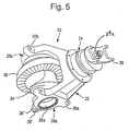
- the drive axle assembly 1 further comprises a differential assembly module 20 illustrated in detail in Fig. 5.
- the differential assembly module 20 is fastened to the enlarged central plate section 4 of the support beam member 2.
- Two opposite axle shaft members 14a and 14b outwardly extend from the differential asse mbly module 20 and are rotatably supported by the arm sections 6a and 6b of the support beam member 2 so that the axle shaft members 14a and 14b are spaced from the central plate section 4 of the beam member 2 in the driving direction F of the motor vehicle.
- Distal ends of the axle shaft members 14a and 14b are provided with flange members 15a and 15b, respectively, adapted for mounting corresponding wheel hubs (not shown).
- the differential assembly module 20 includes a differential carrier frame member 22 fastened to the central plate section 4 of the beam member 2, and provided for rotatably supporting a differential case 34 and a drive pinion 38.
- the differential case 34 houses a differential gear mechanism, well known to those skilled in the art.
- the drive pinion 38 has a pinion gear 38a in continuous meshing engagement with a ring gear 36, and a pinion shaft 38b operatively coupled to a vehicular propeller shaft (not shown) driven by a vehicular powerplant (not shown), such as an internal combustion en gine, through an input yoke 39.
- a mounting companion flange may be attached to a distal end of the pinion shaft 38b (instead of the input yoke 39) for coupling the pinion shaft 38b to the vehicular propeller shaft driven by the vehicular powerplant.
- the ring gear 36 is conventionally secured to the differential case 34 in any appropriate manner well known in the art.
- the differential assembly module 20 of the present invention is a self - contained unit wherein the differential carrier frame member 22 supports all the significant elements of the differential assembly and a final drive, such as the differential case 34 housing the differential gear mechanism, anti-friction differential bearings 35a and 35b, adjusting ring s 32a and 32b for adjustment of a bearing preload and/or proper positioning of the differential case 34 relative to the differential carrier frame member 22, locks for the adjusting rings 32a and 32b, oil seals, the drive pinion 38, drive pinion bearings, and the input yoke 39.
- the differential carrier frame member 22 of the present invention improves the modularity of design of the differential assembly, substantially simplifies the assembly and servicing of the differential assembly, and reduces the number of required machining operations.
- Each of the adjusting rings 32a and 32b is provided with external threads 33 on an outer peripheral surface thereof, which are adapted to engage internal threads formed on the differential carrier frame member 22.
- An axi ally outwardly end of each adjusting ring 32a or 32b may be formed to receive a tool for turning the adjusting rings.
- the adjusting rings 32a and 32b will be rotated so as to thread in to or out of the differential carrier frame member 22 for selective adjust the preload of the differential bearings 35a and 35b and position of the differential case 34 relative to the differential carrier frame member 22, as illustrated in Fig. 7.
- the differential assembly module 20 is enclosed into a housing formed by a rear cover 40 and a front cover 46 secured to opposite surfaces of the central plate section 4 of the beam member 2 in any appropriate manner well known in the art.
- both the rear cover 40 and the front cover 46 are manufactured by metal stamping of any appropriate metal material, such as steel.
- the front cover 46 is welded to a front surface of the central plate section 4 of the beam member 2, while the rear cover 40 is fastened to a rear surface of the central plate section 4 of the beam member 2 using conventional fasteners.
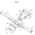
- the front cover 46 has a front opening 48 (shown in Figs.
- the front opening 48 is formed by a front flange collar 49a provided with a plurality of through holes 49' spaced apart substantially circumferentially, equidistantly around the front opening 48.
- the front cover 46 is further provided with a rear flange 49b adapted to juxtapose a front surface of the central plate section 4 of the beam member 2.
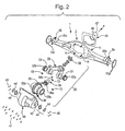
- the rear cover 40 incorporates two opposite through holes 42 (only one is shown in Fig. 2) for receiving the axle shaft members 14a and 14b therethrough.
- Each of the through holes 42 is provided with an adjustable flange device 44 provided with an axle shaft seal 44' adapted to seal the through hole 42 about the axle shaft members 14a and 14b.
- the adjustable flange device 44 is secured to the rear cover 40 adjacent to the through hole 42 therein by a set of screws 45 and is adapted to adjust a position of the axle shaft seal 44' relative to the through hole 42 of the rear cover 40.
- the rear cover 40 is further provided with a mounting flange 43 adapted to juxtapose the rear mounting surfa ce of the central plate section 4 of the beam member 2.
- the mounting flange 43 of the rear cover 40 is provided with a plurality of spaced apart through holes 43'.
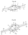
- Fig. 4A depicts in detail the support beam member 2 in accordance with the first exemplary embodiment of the present invention.
- the support beam member 2 has the substantially flat, enlarged central plate section 4 and the two opposite, substantially tubular arm sections 6a and 6b axially outwardly extending from the central plate section 4.
- the support beam member 2 is formed of a single - piece C-channel body 8 manufactured by a metal deforming, such as stamping, having a substantially flat, enlarged central plate portion 8c and two opposite arm portions 8a and 8b axially outwardly extending from the central plate section 8c.
- the flat central plate portion 8c of the body 8 is in the form of a substantially vertically oriented flat plate.
- the enlarged central plate portion 8c of the body 8 defines the central plate section 4 of the support beam member 2.
- the enlarged central plate portion 8c has substantially flat front and rear mounting surfaces 8 F and 8 R , respectively.
- the central plate portion 8c is further provided with a central opening 10 therethrough adapted for receiving the differential carrier frame member 22 of the differential assembly module 20.
- the central plate section 8c of the body 8 of the support beam member 2 is provided with a plurality of threaded mounting studs 9 fixed to the rear mounting surface 8 R of the central plate portion 8c, in combination with complementary internally threaded nuts 13.
- the mounting studs 9 extend rearwardly from the rear mounting surface 8 R of the central plate section 8c.
- the mounting studs 9 extend substantially orthogonally to the rear mounting surface 8 R of the central plate portion 8c.
- a plurality of smaller mounting holes 11 are formed in the central plate section 8c adjacent to the central opening 10 provided for receiving the screws 41 adapted to fasten the rear cover 40 to th e central plate section 4 of the support beam member 2.
- the mounting holes 11 are provided with threads complementary to threads of the screws 41.
- the mounting holes 11 may be smooth, and a plurality of bolts with complementary nuts (not shown) are provided in order to fasten the rear cover 40 to the flat central plate section 4 of the support beam member 2.
- the mounting holes 11 may be smooth, and each of the mounting holes 11 is provided with a weld -on nut adapted to threadedly engage the complementary screws 41.
- the support beam member 2 further includes two structural plates 12a and 12b attached to the arm sections 8a and 8b, respectively, in any appropriate manner, such as welding, so as to form the subs tantially tubular arm sections 6a and 6b of the support beam member 2 housing the axle shaft members 14a and 14b.
- the tubular arm sections 6a and 6b of the support beam member 2 have substantially rectangular cross -section.
- Inward ends of each of the structural plates 12a and 12b is provided with a notch 16 receiving the axle shaft member 14a or 14b therethrough in a spaced relationship with respect to the central plate section 8c of the body 8 of the support beam member 2.
- Fig. 4B depicts a second exemplary embodiment of a support beam member indicated with the reference numeral 102 in accordance with the second exemplary embodiment of the present invention.
- the support beam member 102 has a substantially flat, enlarged central section 104 and two opposite arm sections 106a and 106b axially outwardly extending from the central section 104.
- the support beam member 102 is formed of a single -piece C-channel body 108 manufactured by a metal deforming, such as stamping, having a substantially flat, enlarged central section 108c and two opposite arm sections 108a and 108b axially outwardly extending from the central section 108c.
- the substantially flat, enlarged central section 108c of the body 108 defines the central section 104 of the support beam member 102.
- the flat enlarged central section 108c is further provided with a central opening 110 therethrough adapted for receiving the differential carrier frame member 22 of the differential assembly 20.
- a plurality of threaded mounting studs 109 are fixed to a rear mounting surface 108 R of the central plate portion 108c, in combination with complementary internally threaded nuts (not shown).
- the mounting studs 109 extend rearwardly from the rear mounting surface 108 R of the central plate section 108c.
- the mounting studs 109 extend substantially orthogonally to the rear mounting surface 108 R of the central plate portion 108c.
- the arm sections 108a and 108b of the C -channel body 108 are plastically deformed to form a substantially cylindrical arm sections 106a and 106b with seam welds 116 along a neutral axis of the thereof.
- the cylindrical arm sections 106a and 106b of the support beam member 102 houses the axle shaft members 14a and 14b (not shown in Fig. 4B) in a spaced relationship with respect to the flat central section 108c of the body 108 of the support beam member 102.
- arm sections 106a and 106b may have many other shapes that could be used for the same purpose, such as elliptical.
- the support beam member 102 is formed of a single -piece C-channel body 108.
- the differential carrier frame member 22, illustrated in detail in Fig. 6, is, preferably, a single-piece metal part manufactured by casting or forging.
- the differential carrier frame member 22 has a generally Y -shaped configuration and includes a neck portion 24 and two opposite, axially spaced, coaxial bearing hub portions 26a and 26b attached to the neck port ion 24 through respective leg portions 28a and 28b.
- the neck portion has an opening 25 therethrough adapted for receiving and rotatably supporting the drive pinion 38 through an appropriate anti-friction bearing (not shown), preferably a tapered roller bea ring.
- the bearing hub portions 26a and 26b are provided with respective openings 27a and 27b therethrough adapted for receiving appropriate anti -friction bearings 35a and 35b for rotatably supporting the differential carrier 34. Moreover, an inner peripher al surface of each of the openings 27a and 27b has threads 29a and 29b (as shown in detail in Fig. 6) provided to engage the threads 33 of the threaded adjusting ring 32a or 32b, respectively. Each adjusting ring 32a or 32b is threadedly engaged with the threaded openings 27a and 27b in the bearing hub portions 26a and 26b of the differential carrier frame member 22. Also, each of the bearing hub portions 26a and 26b has associated therewith a locking key 26' which is fastened to the bearing hub portion by any appropriate means known in the art, such as a threaded screw 26", as illustrated in Fig. 5.
- the adjusting rings 32a and 32b will be rotated by the tool so as to move them in or out of openings 27a and 27b in the bearing hub portions 26a and 26b, i.e. toward or away from the differential bearings 35a and 35b, for selective adjust their position relative to the differential carrier frame member 22 in order to vary a pressure applied to the differential bearings 35a and 35b, thus preloading the differential bearings 35a and 35b.
- the differential bearings 35a and 35b are properly preloaded to a predetermined preload in accordance with vehicle manufacturer's specifications.
- the anti-friction bearings 35a and 35b are tapered roller bearings.
- the bearing hub portions 26a and 26b are provided with mounting flange portions 30a and 30b respectively, for fastening the differential carrier frame member 22 to the flat central plate section 4 of the support beam member 2.
- each of the mounting flange portions 30a and 30b has two mounting bores 31a and 31b, respectively, adapted to receive the mounting studs 9.
- the fully assembled differential assembly module 20 is secured to the support beam member 2 by mounting the differential carrier frame member 22 to the central plate section 4 of the beam member 2 through the mounting studs 9 extending through the mounting bores 31a and 31b in the differential carrier frame member 22, and fastening it to the central plate section 4 of the support beam member 2 with the complementary nuts 13.
- a geometric location of the mounting studs 9 is substantially complementary to location the mounting bores 31a and 31b of the mounting flange portions 30a and 30b of the differential carrier frame member 22 when the anti -friction bearings 35a and 35b mounted to the differential carrier frame member 22 are properly preloaded to the predetermined pre load.
- geometric centers of the mounting bores 31a and 31b of the mounting flange portions 30a and 30b of the differential carrier frame member 22 are axially spaced to a first distance S H .
- the distance be tween the geometric centers of the mounting bores 31a and 31b of the mounting flange portions 30a and 30b of the differential carrier frame member 22 increases to a second distance S HP , as shown in Fig. 8 (only the differential carrier frame member 22 of t he differential assembly module 20 is shown, the differential case 34 and the differential bearings 35a and 35b are omitted for clarity).
- a geometric location of the mounting studs 9 is substantially complementary to location the mounting bores 31a and 31b of the mounting flange portions 30a and 30b of the differential carrier frame member 22 in a preloaded condition, i.e. an axial distance between geometric centers of the mounting studs 9 in a transverse direction substantially corresponds to the second distance S HP between the geometric centers of the mounting bores 31a and 31b of the mounting flange portions 30a and 30b of the differential carrier frame member 22 when the differential bearings 35a and 35b are properly preloaded to the predetermined value in accordance with the vehicle manufacturer's specifications (as shown in Fig. 8).
- the differential carrier frame member 22 of the differential assembly module 20 is shown in Fig. 8, the differential case 34 and the differential bearings 35a and 35b are omitted for clarity.
- a distance between geometric centers of the mounting studs 9 in a vertical direction substantially corresponds to a distance D H between the geometric centers of the mounting bores 31a of the mounting flange portion 30a and the mounting bores 31b of the mounting flange portion 30b of the differential carrier frame member 22.
- the distance D H is not affected by the preloading force acting to the mounting flange portions 30a and 30b of the differential carrier frame member 22.
- the neck portion 24 of the differential carrier frame member 22 has a substantially annular flange member 52 provided with a plurality of holes 54 spaced apart substantially circumferentially, equidistantly around the flange member 52.
- the holes 54 are threaded. It will be appreciated that a geometric location of the through holes 54 is substantially complementary to location the through holes 49' o f the front flange collar 49a of the front cover 46.
- the preferred embodiment of a method of assembling the rigid drive axle assembly 1 in accordance with the present invention is performed in the following manner.
- the differential assembly module 20 is assembled by mounting and securing the differential case 34 housing a differential gear mechanism and the drive pinion 38 to the differential carrier frame member 22.
- the input yoke 39 is attached to the distal end of the drive pinion 38 by any appropriate means well known in the art, such as spline connection, and secured by a threaded nut 39a.
- the differential bearings 35a and 35b are preloaded by the adjusting rings 32a and 32b to a predetermined bearing preload in accordance with a manufacturer's specification. Differential bearings supporting the drive pinion 38 are also preloaded.
- the fully assembled and preloaded differential assembly module 20 is mounted to the support beam member 2 by fastening the differential carrier frame member 22 to the rear mounting surface 8 R of the support beam member 2 so that the neck portion 24 of the differential carrier frame member 22 extends through the opening 10 in the central plate section 4 of the support beam member 2.
- the mounting flange portions 30a and 30b of the differential carrier frame member 22 are fastened to the rear mounting surface 8 R of the enlarged, central plate section 8c of the body 8 of the support beam member 2 by inserting the mounting bores 31a and 31b of the moun ting flange portions 30a and 30b of the differential carrier frame member 22 over the mounting studs 9 to extend them through the mounting bores 31a and 31b in the differential carrier frame member 22, then fastening to the central plate section 4 of the beam member 2 with the complementary nuts 13.
- the differential carrier frame member 22 of the differential assembly module 20 is shown in Figs. 8 and 9, the differential case 34 and the differential bearings 35a and 35b are omitted for clarity.
- the predetermined bearing preload of the differential bearings 35a, 35b in the differential assembly module 20 could be readily and conveniently verified.
- the front cover 46 is placed over the neck portion 24 of the differential carrier frame member 22 of the differential assembly module 20 so that the distal end of the pinion shaft 38b of the drive pinion 38 of the differential assembly module 20 extends through the opening 48 in the front cover 46 and the front flange collar 49a of the front cover 46 is juxtaposed to the annular flange member 52 of the neck portion 24 of the differential carrier frame member 22.
- the front flange collar 49a of the front cover 46 is fastened to the annular flange member 52 of the neck portion 24 of the differential carrier frame member 22 by a plurality of screws 47 extending through the through holes 49' of the front flange collar 49a of the front cover 46 and threaded into the threaded holes 5 4 in the annular flange member 52 of the neck portion 24 of the differential carrier frame member 22.
- the front cover 46 is secured to the central plate section 8c of the C -channel body 8 of the support beam member 2 by welding the rear flang e 49b of the front cover 46 to the front mounting surface 8 F of the central plate section 8c. It will be appreciated that any other techniques of securing the front cover 46 to the front mounting surface 8 F , such as adhesive bonding, bolting, riveting, etc., is within the scope of the present invention.
- the process in accordance with the present invention represents a novel method for verifying a predetermined bearing preload of a differential assembly module mounted to an axle support beam memb er of a drive axle.
- the present invention considerably simplifies assembling of the drive axle, reduces labor cost and improves the quality of the final product.
Landscapes
- Engineering & Computer Science (AREA)
- General Engineering & Computer Science (AREA)
- Mechanical Engineering (AREA)
- Chemical & Material Sciences (AREA)
- Combustion & Propulsion (AREA)
- Transportation (AREA)
- Motor Power Transmission Devices (AREA)
- Retarders (AREA)
- General Details Of Gearings (AREA)
Abstract
A rigid drive axle assembly (1) includes a support beam member (2) having a substantially flat
central plate section (4), a differential assembly module (20) secured to the central plate section (4)
through at least two threaded studs (9) extending from the central plate section (4). The differential
assembly module (20) includes a differential carrier frame member (22) having two bearing hubs (26a,26b)
receiving differential bearings (35a,35b). A method for verifying a predetermined bearing preload of the
differential assembly module (20) comprises the steps of preloading the differential bearings (35a,35b) to the
predetermined bearing preload, inserting mounting bores (31a,31b) in the bearing hubs (26a,26b) of the frame
member (22) onto the mounting studs (9), and determining that the differential bearings (35a,35b) are properly
preloaded if the mounting studs (9) are received in the mounting bores (31a,31b) in the differential carrier
frame member (22) without substantial resistance, or determining that the differential bearings (35a,35b) are
not properly preloaded if the mounting studs (9) may not be received in the mounting bores (31a,31b) easily.
A further independent claim is included for a method of assembling a
drive axle.
Description
The present invention relates to drive axle assemblies for motor vehicles and methods
for assembling the same in ge neral, and more particularly to a method for verifying
predetermined bearing preload of a differential assembly module during the operation of
mounting the differential assembly module to a support beam member of the drive axle
assembly.
Drive axle assemblies are in common use in most motor vehicles. Such axle assemblies
include a number of components that are adapted to transmit rotational power from an engine
of the motor vehicle to wheels thereof. Typically, the drive ax le assembly includes a hollow
axle housing, a differential assembly, which is rotatably supported within the axle housing by a
non-rotating differential carrier. The differential assembly drivingly couples an input drive shaft
extending from the vehicle en gine and a pair of output axle shafts extending to the vehicle
wheels. Typically, the axle shafts are contained in respective non -rotating tubes of the axle
housing. Thus, rotation of a gear mechanism of the differential assembly by the drive shaft
causes corresponding rotation of the axle shafts.
Typically, a differential case of the differential assembly is rotatably supported by the
differential carrier through a pair of single row tapered roller bearings adapted to accurately
center the differential case within the differential carrier and accurately position a ring gear
relative to a drive pinion. Proper engagement of the ring gear carried by the differential case
with the driving pinion is necessary for proper operation. The differential case must ro tate
with considerable precision, lest the ring gear will not mesh properly with a drive pinion gear
of a final drive assembly and thereby produce noise and excessive wear. To achieve this
precision, the differential case and the differential carrier must not only be machined
accurately, but the bearings must be set properly to a condition of an appropriate,
predetermined preload where no radial or axial end play exists in the differential case. The
preload in the bearings imparts rigidity to the differential case, but too much preload will
cause the bearings to overheat and fail prematurely. On the other hand, too little preload may
cause the bearings to acquire the end play, and this likewise decreases the life of the bearings
and introduces radial and axial play into the differential case.
Generally, the prior art differential case bearings have been made adjustable by means
of adjustment shims or threaded sleeve adjusters used to provide the predetermined preload on
the differential case bearings accordin g to manufacturer's specification.
Typically, the differential case bearings are disposed within the differential carrier and
preloaded to the predetermined preload prior to mounting the differential case within the
differential carrier. The accuracy of he differential bearing preload depends largely on a
workmen's experience. After that, the assembled differential carrier is fastened to an axle
housing of the drive axle.
Unfortunately, common assembly problems do affect differential bearing preload, such
as: (1) improper fitting or misalignment of either the outer bearing race rings into the
differential carrier bore or the inner bearing race rings onto the differential case, (2) presence
of foreign particles in or about the race rings, and (3) workmen's skill in wrongly controlling
compression to obtain the predetermined preload as a result of torquing the threaded sleeve
adjusters. If such problems are not detected prior to putting the differential assembly into
service, it will have a useful life signif icantly shortened, and often irreparable damage could be
done requiring replacement of bearings or other components.
However, if the differential bearing assemblies are not properly preloaded, then it is
practically impossible to verify the accuracy of th bearing preloading during the process of
assembling the drive axle. When it is realized during the testing or operation of the drive axle
that the differential bearings are not properly preloaded, the axle has to be disassembled, the
differential carrier dismantled from the axle housing and the preload of the differential bearings
has to be adjusted. It may require several disassembling -reassembling operations before the
correct bearing preload is achieved. Such labor -intensive procedures add cost and complexity
to the drive axle manufacturing procedure.
Thus, there is a need for a method for verifying a predetermined bearing preload of the
differential assembly during the process of assembling of the drive axle that enables plant
personnel to quickly determine differential bearing preload conditions to see if they all fall
within specific design parameters, thus preventing premature axle failure and enhancing
reliability of the differential assembly.
The present invention provides a novel method for verifying a predetermined bearing
preload of differential bearings in a differential assembly module during the mounting thereof
to a drive axle assembly. The drive axle assembly in accordance with the preferred embodiment
of the present invention is a rigid drive axle assembly and comprises a support beam member
having a substantially flat, enlarged central plate section and two opposite arm sections
extending axially outwardly from the central plate section. The flat enlarged central section is
further provided with a central opening therethrough. It will be appreciated that the present
invention is equally applicable to independent drive axle assemblies, and may be used for both
front and rear axle applications.
The drive axle assembly further comprises a differential assembly module fastened to
the enlarged central plate section of the support beam member, and two opposite axle shaft
members outwardly extending from the differential assembly module, and rotatably supported
by the arm sections of the support beam member so that the axle shaft members are spaced
from the central plate section of the support beam member in a driving direction of the motor
vehicle. Distal ends of the axle shaft members are provided with flange member s adapted for
mounting corresponding wheel hubs. The differential assembly module is enclosed into a
housing formed by a rear cover and a front cover secured to opposite surfaces of the central
plate section of the beam member.
The differential assembly mo dule includes a differential carrier frame member fastened
to the central plate section of the support beam member, and provided for rotatably supporting
a differential case and a drive pinion. The differential case houses a conventional differential
gear mechanism, well known to those skilled in the art. The drive pinion has a pinion gear in
continuous meshing engagement with a ring gear, and a pinion shaft operatively coupled to a
vehicular drive shaft driven by a vehicular powerplant. The differential assembly module is
enclosed into a housing formed by a rear cover and a front cover secured to opposite surfaces
of the central plate section of the beam member in any appropriate manner well known in the
art. The front cover has a front opening for rotata bly supporting and receiving therethrough a
distal end of the pinion shaft of the drive pinion. The rear cover incorporates two opposite
through holes for receiving the axle shaft members therethrough. Each of the through holes is
provided with a self-centering seal.
The differential carrier frame member is, preferably, a single -piece metal part
manufactured by casting or forging. The differential carrier frame member has a generally Y -
shaped configuration and includes a neck portion and two opposite, axially spaced, coaxial
bearing hub portions attached to the neck portion through respective leg portions. The neck
portion has an opening therethrough adapted for receiving and rotatably supporting the drive
pinion through appropriate anti -friction bearings, preferably roller bearings. The bearing hub
portions are provided with respective openings therethrough adapted for receiving appropriate
anti-friction bearings for rotatably supporting the differential carrier, and threaded adjusting
rings provided for pr eloading the anti-friction bearings of the differential assembly module to a
predetermined bearing preload in accordance with a manufacturer's specification. Moreover,
the bearing hub portions are provided with mounting flange portions having mounting bores.
The differential assembly module is secured to the central plate section of the central
plate section of the support beam member through at least two threaded studs extending from
the central plate section. In an assembled condition, the threaded studs extend through the
mounting bores in the differential carrier frame member, and fastened to the central plate
section of the beam member with the complementary nuts. A geometric location of the
mounting studs is substantially complementary to the locatio n of the mounting bores of the
mounting flange portions of the differential carrier frame member in a preloaded condition.
A method for verifying a predetermined bearing preload of the differential assembly
module comprises the steps of preloading the differential bearings to the predetermined bearing
preload, inserting mounting bores in the bearing hubs of the frame member onto the mounting
studs, and determining that the differential bearings are properly preloaded if the mounting
studs are received in the mounting bores in the differential carrier frame member without
substantial resistance, or determining that the differential bearings are not properly preloaded if
the mounting studs may not be received in the mounting bores easily.
Therefore, the proces s in accordance with the present invention represents a novel
method for verifying a predetermined bearing preload of a differential assembly module
mounted to an axle support beam member of a drive axle. The present invention considerably
simplifies assembling of the drive axle, reduces labor cost, improves the quality of the final
product and enhances reliability of the differential assembly.
Other objects and advantages of the invention will become apparent from a study of the
following specification when viewed in light of the accompanying drawings, wherein:
The preferred embodiment of the present invention will now be described with the
reference to accompanying drawings. As used herein, the words "front" and "rear" in the
following description are referred with respect to a driving direction of a motor vehicle (not
shown), as indicated in the accompanying drawing figures by an arrow F.
Figs. 1-2 depict a vehicle rigid drive axle assembly 1 in accordance with the first
exemplary embodiment of the present invention. It will be appreciated that the present
invention is equally app licable to an independent drive axle assembly, and may be used for both
front and rear axle applications.
The rigid drive axle assembly 1 comprises a support beam member 2 having a
substantially flat, enlarged central plate section 4 and two opposite, substantially tubular arm
sections 6a and 6b axially outwardly extending from the central plate section 4. As illustrated,
the flat central plate section 4 of the support beam member 2 is in the form of a substantially
vertically oriented flat plate and define s a support plane that is substantially orthogonal to the
driving direction F of the motor vehicle. Preferably, the arm sections 6a and 6b are formed
integrally with the central plate section 4.
The drive axle assembly 1 further comprises a differential assembly module 20
illustrated in detail in Fig. 5. The differential assembly module 20 is fastened to the enlarged
central plate section 4 of the support beam member 2. Two opposite axle shaft members 14a
and 14b outwardly extend from the differential asse mbly module 20 and are rotatably
supported by the arm sections 6a and 6b of the support beam member 2 so that the axle shaft
members 14a and 14b are spaced from the central plate section 4 of the beam member 2 in the
driving direction F of the motor vehicle. Distal ends of the axle shaft members 14a and 14b are
provided with flange members 15a and 15b, respectively, adapted for mounting corresponding
wheel hubs (not shown).
The differential assembly module 20 includes a differential carrier frame member 22
fastened to the central plate section 4 of the beam member 2, and provided for rotatably
supporting a differential case 34 and a drive pinion 38. The differential case 34 houses a
differential gear mechanism, well known to those skilled in the art. The drive pinion 38 has a
pinion gear 38a in continuous meshing engagement with a ring gear 36, and a pinion shaft 38b
operatively coupled to a vehicular propeller shaft (not shown) driven by a vehicular powerplant
(not shown), such as an internal combustion en gine, through an input yoke 39. Alternatively, a
mounting companion flange (not shown) may be attached to a distal end of the pinion shaft 38b
(instead of the input yoke 39) for coupling the pinion shaft 38b to the vehicular propeller shaft
driven by the vehicular powerplant. The ring gear 36 is conventionally secured to the
differential case 34 in any appropriate manner well known in the art.
Therefore, the differential assembly module 20 of the present invention is a self -
contained unit wherein the differential carrier frame member 22 supports all the significant
elements of the differential assembly and a final drive, such as the differential case 34 housing
the differential gear mechanism, anti-friction differential bearings 35a and 35b, adjusting ring s
32a and 32b for adjustment of a bearing preload and/or proper positioning of the differential
case 34 relative to the differential carrier frame member 22, locks for the adjusting rings 32a
and 32b, oil seals, the drive pinion 38, drive pinion bearings, and the input yoke 39. The
differential carrier frame member 22 of the present invention improves the modularity of design
of the differential assembly, substantially simplifies the assembly and servicing of the
differential assembly, and reduces the number of required machining operations.
Each of the adjusting rings 32a and 32b is provided with external threads 33 on an
outer peripheral surface thereof, which are adapted to engage internal threads formed on the
differential carrier frame member 22. An axi ally outwardly end of each adjusting ring 32a or
32b may be formed to receive a tool for turning the adjusting rings.
For adjustment and preloading of the differential bearings 35a and 35b, the adjusting
rings 32a and 32b will be rotated so as to thread in to or out of the differential carrier frame
member 22 for selective adjust the preload of the differential bearings 35a and 35b and position
of the differential case 34 relative to the differential carrier frame member 22, as illustrated in
Fig. 7.
In order to prevent the differential assembly module 20 from contamination and
provide a supply of a lubricant, the differential assembly module 20 is enclosed into a housing
formed by a rear cover 40 and a front cover 46 secured to opposite surfaces of the central
plate section 4 of the beam member 2 in any appropriate manner well known in the art. In
accordance with the preferred embodiment of the present invention, both the rear cover 40 and
the front cover 46 are manufactured by metal stamping of any appropriate metal material, such
as steel. Preferably, the front cover 46 is welded to a front surface of the central plate section 4
of the beam member 2, while the rear cover 40 is fastened to a rear surface of the central plate
section 4 of the beam member 2 using conventional fasteners. The front cover 46 has a front
opening 48 (shown in Figs. 2 and 3) for receiving therethrough a distal end of the pinion shaft
38b of the drive pinion 38. As illustrated in Fig. 3, the front opening 48 is formed by a front
flange collar 49a provided with a plurality of through holes 49' spaced apart substantially
circumferentially, equidistantly around the front opening 48. The front cover 46 is further
provided with a rear flange 49b adapted to juxtapose a front surface of the central plate section
4 of the beam member 2.
As shown in Figs. 2 and 3, the rear cover 40 incorporates two opposite through holes
42 (only one is shown in Fig. 2) for receiving the axle shaft members 14a and 14b
therethrough. Each of the through holes 42 is provided with an adjustable flange device 44
provided with an axle shaft seal 44' adapted to seal the through hole 42 about the axle shaft
members 14a and 14b. The adjustable flange device 44 is secured to the rear cover 40 adjacent
to the through hole 42 therein by a set of screws 45 and is adapted to adjust a position of the
axle shaft seal 44' relative to the through hole 42 of the rear cover 40. The rear cover 40 is
further provided with a mounting flange 43 adapted to juxtapose the rear mounting surfa ce of
the central plate section 4 of the beam member 2. As illustrated in Fig. 4, the mounting flange
43 of the rear cover 40 is provided with a plurality of spaced apart through holes 43'.
The opposite arm sections 6a and 6b of the support beam member 2 m ay be provided
with spring seats 50a and 50b, respectively.
Fig. 4A depicts in detail the support beam member 2 in accordance with the first
exemplary embodiment of the present invention. As was explained above, the support beam
member 2 has the substantially flat, enlarged central plate section 4 and the two opposite,
substantially tubular arm sections 6a and 6b axially outwardly extending from the central plate
section 4. Preferably, in this embodiment, the support beam member 2 is formed of a single -
piece C-channel body 8 manufactured by a metal deforming, such as stamping, having a
substantially flat, enlarged central plate portion 8c and two opposite arm portions 8a and 8b
axially outwardly extending from the central plate section 8c.
As illustrated in Fig. 4A, the flat central plate portion 8c of the body 8 is in the form of
a substantially vertically oriented flat plate. The enlarged central plate portion 8c of the body 8
defines the central plate section 4 of the support beam member 2. The enlarged central plate
portion 8c has substantially flat front and rear mounting surfaces 8F and 8R, respectively. The
central plate portion 8c is further provided with a central opening 10 therethrough adapted for
receiving the differential carrier frame member 22 of the differential assembly module 20.
Furthermore, the central plate section 8c of the body 8 of the support beam member 2
is provided with a plurality of threaded mounting studs 9 fixed to the rear mounting surface 8 R
of the central plate portion 8c, in combination with complementary internally threaded nuts 13.
The mounting studs 9 extend rearwardly from the rear mounting surface 8 R of the central plate
section 8c. Preferably, the mounting studs 9 extend substantially orthogonally to the rear
mounting surface 8R of the central plate portion 8c.
In addition, a plurality of smaller mounting holes 11 are formed in the central plate
section 8c adjacent to the central opening 10 provided for receiving the screws 41 adapted to
fasten the rear cover 40 to th e central plate section 4 of the support beam member 2.
Preferably, the mounting holes 11 are provided with threads complementary to threads of the
screws 41. Alternatively, the mounting holes 11 may be smooth, and a plurality of bolts with
complementary nuts (not shown) are provided in order to fasten the rear cover 40 to the flat
central plate section 4 of the support beam member 2. Further alternatively, the mounting holes
11 may be smooth, and each of the mounting holes 11 is provided with a weld -on nut adapted
to threadedly engage the complementary screws 41.
The support beam member 2 further includes two structural plates 12a and 12b
attached to the arm sections 8a and 8b, respectively, in any appropriate manner, such as
welding, so as to form the subs tantially tubular arm sections 6a and 6b of the support beam
member 2 housing the axle shaft members 14a and 14b. As shown in Fig. 4A, the tubular arm
sections 6a and 6b of the support beam member 2 have substantially rectangular cross -section.
Inward ends of each of the structural plates 12a and 12b is provided with a notch 16 receiving
the axle shaft member 14a or 14b therethrough in a spaced relationship with respect to the
central plate section 8c of the body 8 of the support beam member 2.
Fig. 4B depicts a second exemplary embodiment of a support beam member indicated
with the reference numeral 102 in accordance with the second exemplary embodiment of the
present invention. As was explained above, the support beam member 102 has a substantially
flat, enlarged central section 104 and two opposite arm sections 106a and 106b axially
outwardly extending from the central section 104. Preferably, in this embodiment, the support
beam member 102 is formed of a single -piece C-channel body 108 manufactured by a metal
deforming, such as stamping, having a substantially flat, enlarged central section 108c and two
opposite arm sections 108a and 108b axially outwardly extending from the central section
108c.
The substantially flat, enlarged central section 108c of the body 108 defines the central
section 104 of the support beam member 102. The flat enlarged central section 108c is further
provided with a central opening 110 therethrough adapted for receiving the differential carrier
frame member 22 of the differential assembly 20. A plurality of threaded mounting studs 109
are fixed to a rear mounting surface 108 R of the central plate portion 108c, in combination with
complementary internally threaded nuts (not shown). The mounting studs 109 extend
rearwardly from the rear mounting surface 108 R of the central plate section 108c. Preferably,
the mounting studs 109 extend substantially orthogonally to the rear mounting surface 108 R of
the central plate portion 108c.
The arm sections 108a and 108b of the C -channel body 108 are plastically deformed to
form a substantially cylindrical arm sections 106a and 106b with seam welds 116 along a
neutral axis of the thereof. The cylindrical arm sections 106a and 106b of the support beam
member 102 houses the axle shaft members 14a and 14b (not shown in Fig. 4B) in a spaced
relationship with respect to the flat central section 108c of the body 108 of the support beam
member 102. Those of ordinary skill in the art will appreciate that arm sections 106a and 106b
may have many other shapes that could be used for the same purpose, such as elliptical. Thus,
the support beam member 102 is formed of a single -piece C-channel body 108.
The differential carrier frame member 22, illustrated in detail in Fig. 6, is, preferably, a
single-piece metal part manufactured by casting or forging. The differential carrier frame
member 22 has a generally Y -shaped configuration and includes a neck portion 24 and two
opposite, axially spaced, coaxial bearing hub portions 26a and 26b attached to the neck port ion
24 through respective leg portions 28a and 28b. The neck portion has an opening 25
therethrough adapted for receiving and rotatably supporting the drive pinion 38 through an
appropriate anti-friction bearing (not shown), preferably a tapered roller bea ring. The bearing
hub portions 26a and 26b are provided with respective openings 27a and 27b therethrough
adapted for receiving appropriate anti - friction bearings 35a and 35b for rotatably supporting
the differential carrier 34. Moreover, an inner peripher al surface of each of the openings 27a
and 27b has threads 29a and 29b (as shown in detail in Fig. 6) provided to engage the threads
33 of the threaded adjusting ring 32a or 32b, respectively. Each adjusting ring 32a or 32b is
threadedly engaged with the threaded openings 27a and 27b in the bearing hub portions 26a
and 26b of the differential carrier frame member 22. Also, each of the bearing hub portions 26a
and 26b has associated therewith a locking key 26' which is fastened to the bearing hub
portion by any appropriate means known in the art, such as a threaded screw 26", as illustrated
in Fig. 5.
For adjustment, the adjusting rings 32a and 32b will be rotated by the tool so as to
move them in or out of openings 27a and 27b in the bearing hub portions 26a and 26b, i.e.
toward or away from the differential bearings 35a and 35b, for selective adjust their position
relative to the differential carrier frame member 22 in order to vary a pressure applied to the
differential bearings 35a and 35b, thus preloading the differential bearings 35a and 35b. In a
fully assembled condition of the differential assembly module 20, the differential bearings 35a
and 35b are properly preloaded to a predetermined preload in accordance with vehicle
manufacturer's specifications.
Preferably, the anti-friction bearings 35a and 35b are tapered roller bearings.
Moreover, the bearing hub portions 26a and 26b are provided with mounting flange portions
30a and 30b respectively, for fastening the differential carrier frame member 22 to the flat
central plate section 4 of the support beam member 2. Preferably, each of the mounting flange
portions 30a and 30b has two mounting bores 31a and 31b, respectively, adapted to receive
the mounting studs 9.
The fully assembled differential assembly module 20 is secured to the support beam
member 2 by mounting the differential carrier frame member 22 to the central plate section 4 of
the beam member 2 through the mounting studs 9 extending through the mounting bores 31a
and 31b in the differential carrier frame member 22, and fastening it to the central plate section
4 of the support beam member 2 with the complementary nuts 13. It will be appreciated that a
geometric location of the mounting studs 9 is substantially complementary to location the
mounting bores 31a and 31b of the mounting flange portions 30a and 30b of the differential
carrier frame member 22 when the anti - friction bearings 35a and 35b mounted to the
differential carrier frame member 22 are properly preloaded to the predetermined pre load.
More specifically, as shown in Fig. 6, geometric centers of the mounting bores 31a and
31b of the mounting flange portions 30a and 30b of the differential carrier frame member 22
(without the preloaded differential bearings 35a and 35b mounted thereto) are axially spaced to
a first distance SH. As the differential case 34 is mounted to the differential carrier frame
member 22 through the differential bearings 35a and 35b and the differential bearings 35a and
35b are properly preloaded, the distance be tween the geometric centers of the mounting bores
31a and 31b of the mounting flange portions 30a and 30b of the differential carrier frame
member 22 increases to a second distance SHP, as shown in Fig. 8 (only the differential carrier
frame member 22 of t he differential assembly module 20 is shown, the differential case 34 and
the differential bearings 35a and 35b are omitted for clarity).
As noted above, in accordance with the present invention a geometric location of the
mounting studs 9 is substantially complementary to location the mounting bores 31a and 31b
of the mounting flange portions 30a and 30b of the differential carrier frame member 22 in a
preloaded condition, i.e. an axial distance between geometric centers of the mounting studs 9
in a transverse direction substantially corresponds to the second distance S HP between the
geometric centers of the mounting bores 31a and 31b of the mounting flange portions 30a and
30b of the differential carrier frame member 22 when the differential bearings 35a and 35b are
properly preloaded to the predetermined value in accordance with the vehicle manufacturer's
specifications (as shown in Fig. 8). Please note that only the differential carrier frame member
22 of the differential assembly module 20 is shown in Fig. 8, the differential case 34 and the
differential bearings 35a and 35b are omitted for clarity.
A distance between geometric centers of the mounting studs 9 in a vertical direction
substantially corresponds to a distance DH between the geometric centers of the mounting
bores 31a of the mounting flange portion 30a and the mounting bores 31b of the mounting
flange portion 30b of the differential carrier frame member 22. The distance DH is not affected
by the preloading force acting to the mounting flange portions 30a and 30b of the differential
carrier frame member 22.
As further illustrated in Fig. 6, the neck portion 24 of the differential carrier frame
member 22 has a substantially annular flange member 52 provided with a plurality of holes 54
spaced apart substantially circumferentially, equidistantly around the flange member 52.
Preferably, the holes 54 are threaded. It will be appreciated that a geometric location of the
through holes 54 is substantially complementary to location the through holes 49' o f the front
flange collar 49a of the front cover 46.
The preferred embodiment of a method of assembling the rigid drive axle assembly 1 in
accordance with the present invention is performed in the following manner.
First, the differential assembly module 20 is assembled by mounting and securing the
differential case 34 housing a differential gear mechanism and the drive pinion 38 to the
differential carrier frame member 22. The input yoke 39 is attached to the distal end of the
drive pinion 38 by any appropriate means well known in the art, such as spline connection, and
secured by a threaded nut 39a. The differential bearings 35a and 35b are preloaded by the
adjusting rings 32a and 32b to a predetermined bearing preload in accordance with a
manufacturer's specification. Differential bearings supporting the drive pinion 38 are also
preloaded.
Then, the fully assembled and preloaded differential assembly module 20 is mounted to
the support beam member 2 by fastening the differential carrier frame member 22 to the rear
mounting surface 8 R of the support beam member 2 so that the neck portion 24 of the
differential carrier frame member 22 extends through the opening 10 in the central plate section
4 of the support beam member 2. More specifically, the mounting flange portions 30a and 30b
of the differential carrier frame member 22 are fastened to the rear mounting surface 8 R of the
enlarged, central plate section 8c of the body 8 of the support beam member 2 by inserting the
mounting bores 31a and 31b of the moun ting flange portions 30a and 30b of the differential
carrier frame member 22 over the mounting studs 9 to extend them through the mounting
bores 31a and 31b in the differential carrier frame member 22, then fastening to the central
plate section 4 of the beam member 2 with the complementary nuts 13. Please note that only
the differential carrier frame member 22 of the differential assembly module 20 is shown in
Figs. 8 and 9, the differential case 34 and the differential bearings 35a and 35b are omitted for
clarity.
It will be appreciated by those skilled in the art that if the differential bearings 35a and
35b are preloaded properly to the appropriate, predetermined preload in accordance with the
manufacturer's specification, then the mounting studs 9 are received in the mounting bores 31a
and 31b in the differential carrier frame member 22 easily, without substantial resistance.
On the other hand, if the mounting studs 9 cannot be received in the mounting bores
31a and 31b in the differential carrier frame member 22 simultaneously, or if the mounting
studs 9 encounter substantial resistance during the process of mounting over the mounting
bores 31a and 31b, then the differential bearings 35a and 35b are not preloaded properly to the
appropriate, predetermined value in accordance with the manufacturer's specifications.
Thus, the predetermined bearing preload of the differential bearings 35a, 35b in the
differential assembly module 20 could be readily and conveniently verified.
Next, the front cover 46 is placed over the neck portion 24 of the differential carrier
frame member 22 of the differential assembly module 20 so that the distal end of the pinion
shaft 38b of the drive pinion 38 of the differential assembly module 20 extends through the
opening 48 in the front cover 46 and the front flange collar 49a of the front cover 46 is
juxtaposed to the annular flange member 52 of the neck portion 24 of the differential carrier
frame member 22. Then, the front flange collar 49a of the front cover 46 is fastened to the
annular flange member 52 of the neck portion 24 of the differential carrier frame member 22 by
a plurality of screws 47 extending through the through holes 49' of the front flange collar 49a
of the front cover 46 and threaded into the threaded holes 5 4 in the annular flange member 52
of the neck portion 24 of the differential carrier frame member 22. Subsequently, the front
cover 46 is secured to the central plate section 8c of the C -channel body 8 of the support beam
member 2 by welding the rear flang e 49b of the front cover 46 to the front mounting surface 8 F
of the central plate section 8c. It will be appreciated that any other techniques of securing the
front cover 46 to the front mounting surface 8 F , such as adhesive bonding, bolting, riveting,
etc., is within the scope of the present invention.
Therefore, the process in accordance with the present invention represents a novel
method for verifying a predetermined bearing preload of a differential assembly module
mounted to an axle support beam memb er of a drive axle. The present invention considerably
simplifies assembling of the drive axle, reduces labor cost and improves the quality of the final
product.
The foregoing description of the preferred embodiments of the present invention has
been presented for the purpose of illustration in accordance with the provisions of the Patent
Statutes. It is not intended to be exhaustive or to limit the invention to the precise forms
disclosed. Obvious modifications or variations are possible in light of the above teachings.
The embodiments disclosed hereinabove were chosen in order to best illustrate the principles
of the present invention and its practical application to thereby enable those of ordinary skill in
the art to best utilize the invention in vari ous embodiments and with various modifications as
are suited to the particular use contemplated, as long as the principles described herein are
followed. Thus, changes can be made in the above -described invention without departing from
the intent and scop thereof. It is also intended that the scope of the present invention be
defined by the claims appended thereto.
Claims (20)
- A method for verifying a predetermined bearing preload of differential bearings in a differential assembly module during the m ounting thereof to an axle support beam member of a drive axle assembly, said axle support beam member having a central section and at least two mounting studs outwardly extending therefrom, said differential assembly module including a differential carrier frame member having two axially spaced bearing hub portions each provided for receiving one of said differential bearings for rotatably supporting a differential case, each of said bearing hub portions of said differential carrier frame member having at least one mounting bore for receiving one of said at least two mounting studs of said support beam member, the axial spacing between said at least two mounting studs being complementary to the spacing between said mounting bores in said bearing hub portion s when said differential bearings are properly preloaded to said predetermined bearing preload, said method comprising the steps of:a) providing said differential carrier frame member;b) mounting one of said differential bearings to each of said bearing hub portions of said differential carrier frame member and a differential case rotatably supported by said differential bearings;c) preloading each of said differential bearings to said predetermined bearing preload;d) providing said support beam member;e) inserting said mounting studs of said axle support beam member into said mounting bores in said bearing hub portions of said differential carrier frame member; andf) determining that said differential bearings are properly preloaded if said mounting studs are received in said mounting bores in said differential carrier frame member without substantial resistance; org) determining that said differential bearings are not properly preloaded if said mounting studs may not be received in said mounting bores in said differential carrier frame member or if said mounting studs are received in said mounting bores in said differential carrier frame member with substantial resistance.
- The method for verifying said predetermined bearing preload of said differential bearings as defined in claim 1, wherein said at least two mounting studs extend substantially orthogonally to a rear mounting surface of said central section of said support beam member.
- The method for verifying said predetermined bearing preload of said differential bearings as defined in claim 1, further including the step of fastening said differential carrier frame member to said central section by threaded nuts complementary to said at least two mounting studs subsequent to the step of determ ining that said differential bearings are properly preloaded.
- The method for verifying said predetermined bearing preload of said differential bearings as defined in claim 1, wherein said central section of said support beam member has an opening there through and substantially flat front and rear mounting surfaces, and wherein said at least two mounting studs outwardly extend from said rear mounting surface of said central plate section of said support beam member.
- The method for verifying said predetermined bearing preload of said differential bearings as defined in claim 1, wherein said axle support beam member has two pairs of said mounting studs outwardly extending from said central section of said axle support beam member, and wherein each of said bearing hub portions of said differential carrier frame member has one pair of said mounting bores.
- The method for verifying said predetermined bearing preload of said differential bearings as defined in claim 3, wherein said central section of said support beam member has an opening therethrough, wherein said differential carrier frame member further includes a neck portion for rotatably supporting a drive pinion and two opposite leg portions each provided with one of said bearing hub portions, and wherein said differential carrier frame member of said differential assembly module is fastened to said rear mounting surface of said central section of said support beam member so that said neck portion of said differential carrier frame member extends through said opening in said support beam member.
- The method for verifying said predetermined bearing preload of said differential bearings as defined in claim 1, wherein each of said bearing hub portions of said differential carrier frame member is provided with a mounting flange portion provided with said at least one mounting bore.
- The method for verifying said predetermined bearing preload of said differential bearings as defined in claim 1, further including the step of adjusting said differential bearing preload subsequent to the step of determining that said differential bearings are not properly preloaded.
- A method for verifying a predetermined bearing preload of differential bearings in a differential assembly module during the mounting thereof to an axle support beam member of a drive axle assembly; said axle support beam member including a central section having an opening therethrough, substantially flat front and rear mounting surfaces and two pairs of mounting studs extending substanti ally orthogonally outwardly from said rear mounting surface of said central plate section of said support beam member; said differential assembly module including a differential carrier frame member having a neck portion and two bearing hub portions for receiving said differential bearings for rotatably supporting a differential case and having axially spaced mounting flange portions; each of said mounting flange portions having a pair of mounting bores for receiving one of said two pairs of mounting studs of said support beam member; an axial spacing between said two pairs of mounting studs is complementary to the spacing between said pairs of mounting bores in said bearing hub portions when said differential bearings are properly preloaded to said predeter mined bearing preload, said method comprising the steps of:a) providing said differential carrier frame member;b) mounting one of said differential bearings to each of said bearing hub portions of said differential carrier frame member and said different ial case rotatably supported by said differential bearings;c) preloading each of said differential bearings to said predetermined bearing preload in accordance with the manufacturer's specification;d) providing said support beam member;e) inserting said mounting studs into said mounting bores in said bearing hub portions of said differential carrier frame member; andf) fastening said differential carrier frame member to said central plate section by threaded nuts complementary to said mounting studs if said mounting studs are received in said mounting bores in said differential carrier frame member without substantial resistance; org) adjusting said differential bearing preload if said mounting studs may not be received in said mounting bores in said differential carrier frame member or if said mounting studs are received in said mounting bores in said differential carrier frame member with substantial resistance; andh) fastening said differential carrier frame member to said central plate section by s aid threaded nuts if said mounting studs are received in said mounting bores in said differential carrier frame member without substantial resistance subsequent to the step of adjusting said differential bearing preload.
- A method for assembling a driv e axle assembly of a motor vehicle, said drive axle assembly comprising a support beam member and a differential assembly module, said method comprising the steps of:a) providing said support beam member having a central section and at least two mounting studs outwardly extending therefrom;b) providing said differential assembly module including a differential carrier frame member having two axially spaced bearing hub each provided for receiving one of differential bearings for rotatably supporting a differential case, each of said bearing hub portions of said differential carrier frame member having at least one mounting bore for receiving one of said at least two mounting studs of said support beam member, wherein an axial spacing between said at least two mounting studs is complementary to the spacing between said mounting bores in said bearing hub portions when said differential bearings are properly preloaded to a predetermined bearing preload;c) mounting one of said differential bearings to each of s aid bearing hub portions of said differential carrier frame member and said differential case rotatably supported by said differential bearings;d) preloading each of said differential bearings to said predetermined bearing preload;e) inserting said mount ing studs into said mounting bores in said bearing hub portions of said differential carrier frame member;f) determining that said differential bearings are properly preloaded if said mounting studs are received in said mounting bores in said differentia 1 carrier frame member without substantial resistance; org) determining that said differential bearings are not properly preloaded if said mounting studs may not be received in said mounting bores in said differential carrier frame member or if said mount ing studs are received in said mounting bores in said differential carrier frame member with substantial resistance; andh) fastening said differential carrier frame member to said central plate section by threaded nuts complementary to said at least two m ounting studs subsequent to the step of determining that said differential bearings are properly preloaded.
- The method for assembling said drive axle assembly as defined in claim 10, wherein said central section has substantially flat front and rear mounting surfaces, and wherein said at least two mounting studs extend from said rear mounting surface.
- The method for assembling said drive axle assembly as defined in claim 11, further including the step of securing a front cover to said front mount ing surface of said central section of said support beam member.
- The method for assembling said drive axle assembly as defined in claim 11, further including the step of securing a rear cover to said rear mounting surface of said central section of said support beam member.
- The method for assembling said drive axle assembly as defined in claim 11, wherein said central plate section of said support beam member has an opening therethrough, wherein said differential carrier frame member further inclu des a neck portion for rotatably supporting a drive pinion and two opposite leg portions each provided with one of said bearing hub portions for rotatably supporting said differential case, and wherein said differential carrier frame member of said differential assembly module is fastened to said rear mounting surface of said central section of said support beam member so that said neck portion of said differential carrier frame member extends through said opening in said support beam member.
- The method for assembling said drive axle assembly as defined in claim 10, wherein each of said bearing hub portions of said differential carrier frame member is provided with a mounting flange portion provided with said at least one mounting bore.
- The method for assembling said drive axle assembly as defined in claim 10, further including the step of adjusting said differential bearing preload subsequent to the step of determining that said differential bearings are not properly preloaded.
- The method for assembling said drive axle assembly as defined in claim 10, wherein said support beam member of said drive axle assembly further includes two opposite arm sections extending from said central section.
- The method for assembling said drive axle assembly as defined in claim 17, wherein said central section of said support beam member is enlarged relative to said arm sections.
- The method for assembling said drive axle assembly as defined in claim 10, wherein said flat central section of said support beam member defines a support plane that is substantially orthogonal to a driving direction of said motor vehicle.
- The method for assembling said drive axle assembly as defined in claim 10, wherein said axle support beam member has two pairs of said mo unting studs outwardly extending from said central section of said axle support beam member, and wherein each of said bearing hub portions of said differential carrier frame member having one pair of said mounting bores.
Applications Claiming Priority (2)
| Application Number | Priority Date | Filing Date | Title |
|---|---|---|---|
| US695900 | 1991-05-06 | ||
| US10/695,900 US7155827B2 (en) | 2003-10-30 | 2003-10-30 | Method for verifying predetermined bearing preload of differential assembly module |
Publications (1)
| Publication Number | Publication Date |
|---|---|
| EP1527935A1 true EP1527935A1 (en) | 2005-05-04 |
Family
ID=34423359
Family Applications (1)
| Application Number | Title | Priority Date | Filing Date |
|---|---|---|---|
| EP04105390A Withdrawn EP1527935A1 (en) | 2003-10-30 | 2004-10-29 | Method for verifying predetermined bearing preload of differential assembly module |
Country Status (5)
| Country | Link |
|---|---|
| US (1) | US7155827B2 (en) |
| EP (1) | EP1527935A1 (en) |
| CN (1) | CN1637403A (en) |
| AU (1) | AU2004224968A1 (en) |
| BR (1) | BRPI0406041A (en) |
Cited By (2)
| Publication number | Priority date | Publication date | Assignee | Title |
|---|---|---|---|---|
| EP3010727A4 (en) * | 2013-09-18 | 2017-02-22 | BYD Company Limited | Axle housing assembly for vehicle and vehicle |
| WO2018060079A1 (en) * | 2016-09-29 | 2018-04-05 | Jaguar Land Rover Limited | A drive assembly for a vehicle |
Families Citing this family (16)
| Publication number | Priority date | Publication date | Assignee | Title |
|---|---|---|---|---|
| GB0409418D0 (en) * | 2004-04-28 | 2004-06-02 | Meritor Heavy Vehicle Sys Ltd | Differential carrier assembly |
| US20080121070A1 (en) * | 2006-08-28 | 2008-05-29 | Krisher James A | Axle and axle components and method of manufacturing |
| US7775928B2 (en) * | 2007-09-21 | 2010-08-17 | American Axle & Manufacturing, Inc. | Differential and bearing arrangement |
| CN101666610B (en) * | 2008-09-06 | 2012-06-06 | 辽宁曙光汽车集团股份有限公司 | System and method for measuring and selecting differential bearing gasket of divided steering drive axle assembly |
| US9120374B2 (en) * | 2011-02-16 | 2015-09-01 | Gkn Driveline North America, Inc. | PTU cantilever ring gear disconnect |
| SE537841C2 (en) * | 2012-05-28 | 2015-11-03 | Scania Cv Ab | Drive shaft for a motor vehicle |
| US8657716B1 (en) * | 2012-09-13 | 2014-02-25 | American Axle & Manufacturing, Inc. | Drive train component with structural cover |
| CN105026776A (en) * | 2013-03-06 | 2015-11-04 | 斯凯孚公司 | Method of setting bearing preload |
| CN103398161B (en) * | 2013-07-23 | 2016-01-13 | 安徽江淮汽车股份有限公司 | The system of selection of dual-clutch transmission bearing pre-tightened frock and adjustment pad |
| CN104747692B (en) * | 2013-12-26 | 2018-02-27 | 上海汽车集团股份有限公司 | The method for improving speed changer assembly precision |
| US9632012B2 (en) * | 2015-07-01 | 2017-04-25 | GM Global Technology Operations LLC | Vehicle differential housing and method of NVH testing |
| DE102015225280A1 (en) * | 2015-12-15 | 2017-06-22 | Zf Friedrichshafen Ag | Differential bearing arrangement for mounting a differential cage |
| JP6622331B2 (en) * | 2018-01-29 | 2019-12-18 | 本田技研工業株式会社 | Jig and assembly method |
| US11691506B2 (en) | 2020-09-30 | 2023-07-04 | Gkn Automotive Limited | Shifting mechanism for a vehicle power transfer unit |
| CN113733887A (en) * | 2021-08-10 | 2021-12-03 | 安徽誉林汽车部件有限公司 | Engine and gearbox support buffer stop |
| CN114161880A (en) * | 2021-10-29 | 2022-03-11 | 苏州渭中科技发展有限公司 | Automobile rear axle assembly |
Citations (2)
| Publication number | Priority date | Publication date | Assignee | Title |
|---|---|---|---|---|
| US20010024989A1 (en) * | 2000-03-27 | 2001-09-27 | Morse David M. | One piece differential bearing adjuster lock and fastener |
| WO2003080366A2 (en) * | 2002-03-20 | 2003-10-02 | Dana Corporation | Modular drive axle assembly for motor vehicles |
Family Cites Families (28)
| Publication number | Priority date | Publication date | Assignee | Title |
|---|---|---|---|---|
| US1076560A (en) * | 1912-06-05 | 1913-10-21 | Ellsworth & Cross | Gearing. |
| US1076559A (en) * | 1912-06-05 | 1913-10-21 | Ellsworth & Cross | Axle for motor-vehicles. |
| US3269214A (en) * | 1962-07-30 | 1966-08-30 | Eaton Yale & Towne | Fabricated truck and trailer axle housing |
| US3412631A (en) * | 1966-09-19 | 1968-11-26 | Clark Equipment Co | Change-speed axle |
| US3792625A (en) * | 1971-06-28 | 1974-02-19 | Skf Ind Trading & Dev | Pinion gear transmission |
| US4310200A (en) * | 1979-12-18 | 1982-01-12 | Olender James P | Drive axle truss assembly |
| US4530144A (en) * | 1983-06-09 | 1985-07-23 | Hagelthorn George A | Method for adjusting and retaining bearings on an axle |
| US4841802A (en) * | 1986-03-27 | 1989-06-27 | Rockwell International Corporation | Modified fast fade drive axle housing |
| DE3916314A1 (en) * | 1989-05-19 | 1990-11-22 | Ford Werke Ag | METHOD AND DEVICE FOR DETERMINING THE REQUIRED EMPLOYMENT OF ROLLER BEARINGS IN GEARBOXES |
| US5271294A (en) * | 1992-05-08 | 1993-12-21 | Dana Corporation | Banjo type axle housing having differential carrier support structure |
| US5297855A (en) * | 1992-07-16 | 1994-03-29 | Dana Corporation | Banjo-type axle housing |
| US5328159A (en) * | 1992-08-18 | 1994-07-12 | Dana Corporation | Axle housing attachment assembly |
| US6418613B1 (en) * | 1998-04-09 | 2002-07-16 | John E. Rode | Bearing assembly adjustable spacer and system for adjusting the same |
| JP3997622B2 (en) * | 1998-08-26 | 2007-10-24 | 株式会社豊田自動織機 | Axle housing |
| US6068571A (en) * | 1999-03-30 | 2000-05-30 | Dana Corporation | Drive axle assembly having a ring gear adjustably secured to a differential case |
| US6227716B1 (en) * | 1999-08-20 | 2001-05-08 | Earl J. Irwin | Differential unit having an adjustable bearing assembly |
| US6409626B1 (en) * | 2000-06-29 | 2002-06-25 | Spicer Technology, Inc. | Axle assembly having a differential case adjustably secured to a housing |
| US6402655B1 (en) * | 2000-06-30 | 2002-06-11 | Spicer Technology, Inc. | Limited slip differential with adjustable preload |
| US6553865B1 (en) * | 2000-08-31 | 2003-04-29 | American Axle & Manufacturing, Inc. | Cover pan mounted vent connector |
| US6497027B1 (en) * | 2000-09-22 | 2002-12-24 | Spicer Technology, Inc. | Method for controlling axle shaft endplay in differential assembly |
| US6450914B1 (en) * | 2001-01-16 | 2002-09-17 | Spicer Technology, Inc. | Adjustable axle shaft endplay |
| US6460268B1 (en) * | 2001-04-02 | 2002-10-08 | Spicer Technology Inc. | Universal bearing pre-load tool and method for using thereof |
| US6729207B2 (en) * | 2002-03-20 | 2004-05-04 | Torque-Traction Technologies, Inc. | Rigid drive axle assembly for motor vehicles |
| US6736544B1 (en) * | 2002-05-31 | 2004-05-18 | Dana Corporation | Vehicle differential and method |
| US7461454B2 (en) * | 2003-01-31 | 2008-12-09 | Arvin Technologies | Method of fabricating a housing assembly |
| US6796031B1 (en) * | 2003-03-14 | 2004-09-28 | The Timken Company | Process for setting bearings and verifying force preload |
| US6865809B2 (en) * | 2003-04-08 | 2005-03-15 | General Motors Corporation | Method of preloading tapered roller bearings |
| US7121972B2 (en) * | 2003-10-30 | 2006-10-17 | Torque-Traction Technologies, Inc. | Adjustable flange device for cover member in drive axle assembly |
-
2003
- 2003-10-30 US US10/695,900 patent/US7155827B2/en not_active Expired - Fee Related
-
2004
- 2004-10-29 BR BR0406041-5A patent/BRPI0406041A/en not_active Application Discontinuation
- 2004-10-29 EP EP04105390A patent/EP1527935A1/en not_active Withdrawn
- 2004-11-01 CN CNA2004100820914A patent/CN1637403A/en active Pending
- 2004-11-01 AU AU2004224968A patent/AU2004224968A1/en not_active Abandoned
Patent Citations (2)
| Publication number | Priority date | Publication date | Assignee | Title |
|---|---|---|---|---|
| US20010024989A1 (en) * | 2000-03-27 | 2001-09-27 | Morse David M. | One piece differential bearing adjuster lock and fastener |
| WO2003080366A2 (en) * | 2002-03-20 | 2003-10-02 | Dana Corporation | Modular drive axle assembly for motor vehicles |
Cited By (3)
| Publication number | Priority date | Publication date | Assignee | Title |
|---|---|---|---|---|
| EP3010727A4 (en) * | 2013-09-18 | 2017-02-22 | BYD Company Limited | Axle housing assembly for vehicle and vehicle |
| US9944123B2 (en) | 2013-09-18 | 2018-04-17 | Byd Company Limited | Axle housing assembly for vehicle and vehicle |
| WO2018060079A1 (en) * | 2016-09-29 | 2018-04-05 | Jaguar Land Rover Limited | A drive assembly for a vehicle |
Also Published As
| Publication number | Publication date |
|---|---|
| BRPI0406041A (en) | 2005-06-28 |
| CN1637403A (en) | 2005-07-13 |
| US20050091851A1 (en) | 2005-05-05 |
| AU2004224968A1 (en) | 2005-05-19 |
| US7155827B2 (en) | 2007-01-02 |
Similar Documents
| Publication | Publication Date | Title |
|---|---|---|
| EP1527935A1 (en) | Method for verifying predetermined bearing preload of differential assembly module | |
| US7137183B2 (en) | Drive axle for motor vehicles and method for assembling the same | |
| EP1367299B1 (en) | Improved vehicle differential | |
| US7500934B2 (en) | Drive system and method of assembly thereof | |
| US9845864B2 (en) | Planet carrier, output gear and spindle assembly | |
| US6227716B1 (en) | Differential unit having an adjustable bearing assembly | |
| EP3372853A1 (en) | Axle assembly having a drive pinion and a bearing preload element | |
| WO2000037830A1 (en) | Vehicle differential | |
| WO2017006716A1 (en) | Motor drive device for vehicle | |
| US7485065B2 (en) | Producing and maintaining a desired bearing preload in a differential mechanism | |
| EP1605178A2 (en) | Flange assembly for supporting a bearing and an end fitting in a driveshaft assembly | |
| US7121972B2 (en) | Adjustable flange device for cover member in drive axle assembly | |
| JP2000304122A (en) | Drive axle assembly and positioning method for positioning ring gear relative to differential case in the assembly | |
| US6792680B2 (en) | Method of making a wheel end assembly with a machined hub having reduced on-vehicle runout | |
| CN110239611B (en) | All-terrain vehicle and steering system thereof | |
| US6796029B2 (en) | Method of making a wheel end assembly with a machined rotor having reduced on-vehicle runout | |
| US6460268B1 (en) | Universal bearing pre-load tool and method for using thereof | |
| US6886987B2 (en) | Hub-bearing assembly for a driving wheel of a vehicle, particularly a truck | |
| EP1803973A1 (en) | Differential assembly provided with an adjustment device, in particular for motor vehicles | |
| US20060000308A1 (en) | Axle assembly with opposed electric motor carrier | |
| CN117584665A (en) | Wheel carrier device for motor vehicles | |
| US20030029041A1 (en) | Bevel gear bearing support arrangement manufacturing method | |
| CN210555085U (en) | All-terrain vehicle and steering system thereof | |
| US20080121070A1 (en) | Axle and axle components and method of manufacturing | |
| RU2744102C1 (en) | Vehicle main gear |
Legal Events
| Date | Code | Title | Description |
|---|---|---|---|
| PUAI | Public reference made under article 153(3) epc to a published international application that has entered the european phase |
Free format text: ORIGINAL CODE: 0009012 |
|
| AK | Designated contracting states |
Kind code of ref document: A1 Designated state(s): AT BE BG CH CY CZ DE DK EE ES FI FR GB GR HU IE IT LI LU MC NL PL PT RO SE SI SK TR |
|
| AX | Request for extension of the european patent |
Extension state: AL HR LT LV MK |
|
| AKX | Designation fees paid | ||
| REG | Reference to a national code |
Ref country code: DE Ref legal event code: 8566 |
|
| STAA | Information on the status of an ep patent application or granted ep patent |
Free format text: STATUS: THE APPLICATION IS DEEMED TO BE WITHDRAWN |
|
| 18D | Application deemed to be withdrawn |
Effective date: 20051105 |