EP1527896A1 - Mobile device - Google Patents
Mobile device Download PDFInfo
- Publication number
- EP1527896A1 EP1527896A1 EP03766663A EP03766663A EP1527896A1 EP 1527896 A1 EP1527896 A1 EP 1527896A1 EP 03766663 A EP03766663 A EP 03766663A EP 03766663 A EP03766663 A EP 03766663A EP 1527896 A1 EP1527896 A1 EP 1527896A1
- Authority
- EP
- European Patent Office
- Prior art keywords
- pivot shaft
- mobile device
- cover member
- section
- device body
- Prior art date
- Legal status (The legal status is an assumption and is not a legal conclusion. Google has not performed a legal analysis and makes no representation as to the accuracy of the status listed.)
- Granted
Links
Images








Classifications
-
- B—PERFORMING OPERATIONS; TRANSPORTING
- B41—PRINTING; LINING MACHINES; TYPEWRITERS; STAMPS
- B41J—TYPEWRITERS; SELECTIVE PRINTING MECHANISMS, i.e. MECHANISMS PRINTING OTHERWISE THAN FROM A FORME; CORRECTION OF TYPOGRAPHICAL ERRORS
- B41J29/00—Details of, or accessories for, typewriters or selective printing mechanisms not otherwise provided for
- B41J29/12—Guards, shields or dust excluders
-
- B—PERFORMING OPERATIONS; TRANSPORTING
- B41—PRINTING; LINING MACHINES; TYPEWRITERS; STAMPS
- B41J—TYPEWRITERS; SELECTIVE PRINTING MECHANISMS, i.e. MECHANISMS PRINTING OTHERWISE THAN FROM A FORME; CORRECTION OF TYPOGRAPHICAL ERRORS
- B41J29/00—Details of, or accessories for, typewriters or selective printing mechanisms not otherwise provided for
- B41J29/38—Drives, motors, controls or automatic cut-off devices for the entire printing mechanism
- B41J29/393—Devices for controlling or analysing the entire machine ; Controlling or analysing mechanical parameters involving printing of test patterns
-
- Y—GENERAL TAGGING OF NEW TECHNOLOGICAL DEVELOPMENTS; GENERAL TAGGING OF CROSS-SECTIONAL TECHNOLOGIES SPANNING OVER SEVERAL SECTIONS OF THE IPC; TECHNICAL SUBJECTS COVERED BY FORMER USPC CROSS-REFERENCE ART COLLECTIONS [XRACs] AND DIGESTS
- Y02—TECHNOLOGIES OR APPLICATIONS FOR MITIGATION OR ADAPTATION AGAINST CLIMATE CHANGE
- Y02E—REDUCTION OF GREENHOUSE GAS [GHG] EMISSIONS, RELATED TO ENERGY GENERATION, TRANSMISSION OR DISTRIBUTION
- Y02E60/00—Enabling technologies; Technologies with a potential or indirect contribution to GHG emissions mitigation
- Y02E60/10—Energy storage using batteries
Definitions
- the present invention relates to a mobile device, and more particularly relates to a mobile device with a pivotally openable/closable cover member.
- a mobile thermal printer has a battery housing for housing a battery and a paper roll housing for housing a paper roll in the body thereof.
- the body is provided with cover members for covering the battery housing and a cover member for covering the paper roll housing. These cover members are pivotally openable/closable, and normally closed when in use.
- Fig. 1A is an illustration showing a battery housing cover mechanism 1 of a related-art mobile thermal printer.
- the cover mechanism 1 has an internal pivot shaft arranged at a section recessed from the outer surface of the printer body.
- Fig. 1B and Fig. 1C respectively show a cover in an open position and in a closed position.
- a mobile thermal printer body 2 a battery housing 3
- a cover member 4 shaft portions 5 of the cover member 4
- a battery B there are shown a mobile thermal printer body 2
- Bearing holes 9 are formed on a recessed section 8 recessed from an outer surface 7 of a side face 6 of the printer body 2.
- the shaft portions 5 of the cover member 4 are fitted in the bearing holes 9, so that the cover member 4 is attached to the printer body 2.
- the cover member 4 is rotated about the shaft portions 5 fitted in the bearing holes 9 to be opened as shown in Fig. 1C. 5
- Fig. 2A is an illustration showing a battery housing cover mechanism 20 of another related-art mobile thermal printer.
- the cover mechanism 20 has an exposed pivot shaft arranged on the outer surface of the printer body.
- Fig. 2B and Fig. 2C respectively show a cover in an open position and in a closed position.
- a mobile thermal printer body 21 a battery housing 22, a cover member 23, pierced arms 24 arranged on the outer surface of the cover member 23, and holes 25.
- a bearing 28 is formed on an outer surface 27 of a side face 26 of the printer body 21.
- a shaft member 29 passing through and supported by the bearing 28 is fitted in the holes 25, so that the cover member 23 is attached to the printer body 21.
- the cover member 23 is rotated about the shaft member 29 to be opened as shown in Fig. 2C.
- Fig. 3A shows a paper roll housing cover mechanism 40 of a related-art mobile thermal printer disclosed in Japanese Patent Laid-Open Publication No. 11-157170.
- a cover member 42 is supported on a thermal printer body 41 by a shaft 43.
- An operations knob 44 is provided at the center of the outer surface of the cover member 42.
- An open/close lever 45 integrally formed with the operations knob 44 and left and right lock levers 46 and 47 are provided on the inner surface of the cover member 42.
- the outer ends of the lock levers 46 and 47 are respectively fitted in recesses 48 and 49 on the inner side of side plates of the printer body 41, while pins 46a and 47a on the inner ends of the lock levers 46 and 47 are fitted in cam holes 45a and 45b of the open/close lever 45.
- the cover mechanism 1 shown in Fig. 1A when in the closed position, is hardly broken even if dropped and good in appearance. However, when in the open position, the cover mechanism 1 is not rigid enough.
- the shaft portions 5 of the cover member 4 are arranged at a section recessed from the outer surface 7 of the side face 6 of the printer body 2, the shaft portions 5 are prevented from receiving a direct impact and being broken even if a user drops the printer on the floor by mistake. Also, since the shaft portions 5 of the cover member 4 are not arranged outside the side face 6 of the printer body 2, the printer has a good appearance. However, as shown in Fig. 1C, an open angle ⁇ 1 of the cover member 4 is restricted at approximately 140 degrees by a shoulder 10 when the cover member 4 abuts thereon. Therefore, if a large force F1 for opening the cover member 4 further wider is applied when a user drops the printer on the floor during battery replacement, a larger force multiplied by leverage is generated in the shaft portions 5 and might break the shaft portions 5.
- the cover mechanism 20 shown in Fig. 2A is hardly broken even if dropped and good in appearance when in the open position. However, when in the closed position, the cover mechanism 20 is not rigid enough to resist the damage of being dropped and has a poor appearance.
- an open angle ⁇ 2 of the cover member 23 can be widened to 180 degrees until the cover member 23 abuts on the side face 26 of the printer body 21. Therefore, even if a force F1 is applied when a user drops the printer on the floor by mistake during battery replacement, no force is generated in the arms 24 and therefore the arms 24 are not broken.
- the cover member 23 is in the closed position, the bearing 28 and the arms 24 are arranged outside the side face 26 of the printer body 21. Therefore, if a user drops the printer on the floor by mistake, the impact is directly transmitted to the arms 24 and might break the arms 24.
- the cover member 23 is in the closed position, the appearance is not good in that the arms 24 are arranged outside the side face 26 of the printer body 21.
- the cover mechanism 40 is also disadvantageous in that the cover member is detachable and therefore easily lost.
- a general object of the present invention is to provide a mobile device to solve at lease one problem mentioned above.
- a specific object of the present invention is to provide a mobile device having a cover member pivotally attached to a mobile device body so as to be openable and closable, comprising a pivot shaft support part to movably support a pivot shaft about which the cover member is rotated, wherein the pivot shaft is moved when the cover member is opened wider than normally opened.
- Another specific object of the present invention is to provide a mobile device having a cover member pivotally attached to a mobile device body so as to be openable and closable, comprising a pivot shaft module including a pivot shaft about which the cover member is rotated, and a frame to support the pivot shaft, and a pivot shaft module support part formed on the mobile device body, supporting the pivot shaft module so that the pivot shaft is movable between a first position inside a recessed section of the mobile device body and a second position outside the recessed section, wherein the pivot shaft module support part is configured to normally support the pivot shaft module in the recessed section of the mobile device body, and to support the pivot shaft on the outside of the recessed section when the cover member is opened wider than normally opened.
- the pivot shaft module is supported, the pivot shaft is more stably supported on the mobile device body as compared to a configuration in which the pivot shaft is directly supported.
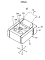
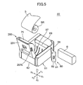
- Figs. 4, 5 and 6 show a mobile line thermal printer 60 according to the embodiment of the present invention.
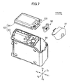
- Fig. 7 is an exploded view of the printer 60.
- the width direction is indicated by a line X1-X2, the longitudinal direction by a line Y1-Y2, and the height direction by a line Z1-Z2.
- the mobile line thermal printer 60 is so configured that a section for storing a print mechanism such as a thermal head and a paper roll, and a section for storing a battery are provided in a generally rectangular solid casing 61, and the size of the printer 60 is suitable to be carried.
- the printer 60 is a clamshell type printer into which a paper roll can be easily loaded.
- the casing 61 of the printer 60 has a casing body 62, a battery housing cover mechanism 80, and a paper roll housing cover mechanism 200.
- the casing body 62 comprises a main body section 63 and a side plate 64 fixed thereto with screws.
- cover members 81 and 201 of the cover mechanisms 80 and 200 are closed, the shape of the casing 61 is generally a rectangular solid.
- the casing body 62 has a battery housing for storing a battery B at the Y1 side, and a paper roll housing 67 for storing a paper roll R at the Z1 side.
- the cover mechanism 80 is provided for the battery housing 66.
- the cover member 81 is so configured to rotate about the line Z1-Z2 between the closed position shown in Fig. 4 and the open position shown in Fig. 5 so as to allow a replacement of the battery B.
- the cover mechanism 200 is provided on the paper roll housing 67.
- the cover member 201 is so configured to rotate about a shaft member 202 on the line X1-X2 between the closed position shown in Fig. 4 and the open position shown in Fig. 5 to allow a paper roll loading.
- the cover member 201 is opened with a biasing force.
- the cover member 201 has a line thermal printhead 75 biased by a spring 76 at the front end, and an operation button 77 at the upper face.
- the housing 66 is covered with the cover member 81 with the battery B located therein and the housing 67 is covered with the cover member 201 with the paper roll SR located therein and a part of a sheet S being pulled out. Also, the sheet S is held between the printhead 75 and the platen rubber roller 69.
- the printhead 75 and the motor 68 are driven to print the sheet S and discharge the sheet S in the arrow 78 direction.
- Fig. 8 is an exploded view showing the cover mechanism 80 of the printer 60.
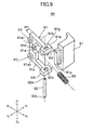
- Fig. 9 is an exploded view showing a pivot shaft module 90 shown in Fig. 8.
- Fig. 10 is an illustration showing a pivot shaft module support structure 100 supporting the pivot shaft module 90.
- the cover mechanism 80 has the cover member 81, the pivot shaft module 90, and the pivot shaft module support structure 100.
- the cover member 81 is generally L shaped, having a hook-like bearing 81a and projections 81b on one side and hooks 81c on the other side.
- the cover member 81 also has an operations knob 82 with a latch 82a.
- the pivot shaft module 90 as shown in Fig. 9, comprises a U-shaped frame member 91, a pivot shaft 92, and a compression coil spring 93.
- the U-shaped frame member 91 has a base section 91a, arms 91b and 91c extending from both sides of the base section 91a, a short column 91d at the center of the base section 91a, and bearings 91e and 91f on the respective tip ends of the arms 91b and 91c.
- a width W2 of the bearings 91e and 91f in the X1-X2 direction is greater than a width W1 of the arms 91b and 91c.
- the bearings 91e and 91f respectively have bearing holes 91g and 91h elongated in the width W2 direction. The bearing holes 91g and 91h are described below in more detail.
- the base section 91a has enlarged sections 91a1 and 91a2 one on each side thereof to form a recessed section on which the column 91d is arranged, so that the compression coil spring 93 is easily fitted.
- Circular projections 91i and 91j are respectively formed on the enlarged sections 91al and 91a2 of the frame member 91 at the X1 side.
- the pivot shaft 92 has thin shaft portions 92a and 92b one on each.
- the shaft portions 92a and 92b are fitted in the bearing holes 91g and 91h, so that the pivot shaft 92 is held between the bearings 91e and 91f.
- the pivot shaft 92 can move within the bearing holes 91g and 91h in the X1-X2 direction.
- the compression coil spring 93 is fitted on the column 91d between the enlarged sections 91a1 and 91a2 at the inner side of the frame member 91.
- Pivot shaft 92 of the pivot shaft module 90 described previously is fitted in the bearing 81a, so that the cover member 81 is attached to the pivot shaft module 90.
- any spring member having the same function as the compression coil spring 93 may be installed between the frame member 91 and a support box 101, which is described later, or the like.
- the pivot shaft module support structure 100 is configured like a pocket defined by the support box 101 and a wall 66a.
- the support box 101 is integrally formed with the side plate 64, having a size corresponding to the frame member 91 and a generally box shape.
- the support box 101 is formed at a U-shaped cutout 104 on the Y2 side end of the side plate 64, having a support plate 102 on the Y2 side, and a U-shaped surrounding section 103 around the support plate 102.
- a receiving plate 105 is formed to extend toward the Y1 direction from the support plate 102.
- a recessed section 107 recessed from an outer surface 106 of the side plate 64 is formed at the inner side of the cutout 104 and at the X1 side of the receiving plate 105.
- the support plate 102 has two guide holes 108 and 109 elongated in the X1-X2 direction.
- the main body section 63 has recesses 110 at the open side of the battery housing 66.
- the side plate 64 has recesses 111 on its end in the Y1 direction.
- the pivot shaft module 90 with the cover member 81 attached thereto is located in the support box 101 and supported by the pivot shaft module support structure 100.
- the frame member 91 is fitted in the support box 101 with the projections 91i and 91j respectively fitted in the guide holes 108 and 109. Tap screws 117 and 118 are threaded from the Y2 side of the support plate 102 into the projections 91i and 91j through washers 115 and 116.
- the pivot shaft module 90 is thus supported by the support plate 102 to be movable in the X1 direction. The displacement in the Y1 direction of the pivot shaft module 90 is restricted by the washers 115 and 116.
- the pivot shaft 92 and the bearing 81a are positioned on the upper side of the receiving plate 105.
- the upper end of the compression coil spring 93 abuts on the lower surface of the receiving plate 105, biasing the frame member 91 in the X2 direction. Accordingly, the pivot shaft module 90 is pushed in the casing body 62.
- the pivot shaft 92, the bearing 81a and the bearings 91e and 91f are located in a first position P1, or, in the recessed section 107.
- Figs. 11A, 11B and 11C are illustrations each showing the cover member 81 in the closed position.
- the cover member 81 is flush with the side plate 64.
- the cover member 81 is locked in the closed position, with the latch 82a of the operations knob 82 holding the inner face of the housing 66, the hooks 81c engaging the recesses 110, and the projections 81b engaging the recesses 111. If an impact is applied to the printer 60 when, for example, dropped on the floor by mistake, the impact in the Y1 direction is absorbed by the latch 82a. If the impact is applied in the X1 direction, the battery B pushes the inner face of the cover member 81 in the X1 direction so as to jump out from the housing 66.
- a force F10 to open the cover member 81 from the inside is applied to the cover member 81.
- the force F10 is received at both ends of the force F10 by the engagement of the hooks 81c and the recesses 110 and the engagement of the projections 81b and the recesses 111. Accordingly, even if an impact is applied to the printer 60, the cover member 81 is not easily opened.
- the bearings 91e and 91f, the bearing 81a, and the pivot shaft 92 are located in the recessed section 107 without projecting outwardly onto the side face 106 of the casing body 62, the bearings 91e and 91f and the bearing 81a are preventing from hitting directly on the floor and receiving direct impact even if the printer 60 is dropped on the floor by mistake. Therefore, the pivot shaft module 90 is prevented from being broken.
- the printer 60 since there are no projections outside the side face 106 of the casing body 62, the printer 60 has a good appearance and can be smoothly stored in a carry case.
- a user releases the lock by performing a first operation indicated by an arrow 1 ⁇ shown in Fig. 11A and then a second operation indicated by an arrow 2 ⁇ .
- Figs. 12A and 12B respectively show the state after the first operation and the state after the second operation.
- the first operation is an operation to slide the operations knob 82 in the X1 direction. With this operation, the inner face of the housing 66 is released from the latch 82a.
- the second operation is an operation to pull the cover member 81 in the Y1 direction. This operation allows the hooks 81c to come out of the recesses 110 and the projections 81b to come out of the recesses 111 and thus releases the engagement.
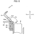
- the cover member 81 is rotated and opened as shown in Fig. 13.
- the open angle ⁇ 10 of the cover member 81 is approximately 140 degrees, and a part of the cover member 80 indicated by a reference numeral 81d near the bearing 81a abuts on an inward edge 104a of the cutout 104 of the side plate 64.
- the battery B is replaced in this state.
- the cover member 81 is closed and locked as shown in Figs. 11A, 11B and 11C by performing the above operation in reverse order.
- the cover member 81 is opened excessively until it abuts on the side face 106 of the casing body 62. In this state, the force F1 is received by the side face 106 of the casing body 62. The cover member 81 is not opened further wider, and no further force is applied on the pivot shaft module 90.
- pivot shaft 92 is formed integrally with the cover member 81, it is possible to move the pivot shaft 92 in the X1 direction as described above.
- the bearing holes 91g and 91h are described below with reference to Fig. 15A and 15B.
- the bearing hole 91h is formed in a generally ellipse shape elongated in the Y1-Y2 direction, having a first circular hole 91h1 at the Y1 side, a second circular hole 91h2 at the Y2 side and a narrow section 91h3 between the holes 91h1 and 91h2.
- the bearing hole 91g is formed in the same shape, having a first circular hole 91g1 at the Y1 side, a second circular hole 91g2 at the Y2 side and a narrow section 91g3 between the holes 91g1 and 91g2.
- the pivot shaft 92 is located in a position Q1 at the Y1 side with the shaft portions 92b and 92a respectively fitted in and supported by the first circular holes 91h1 and 91g1.
- the pivot shaft 92 is located in this position when the cover member 81 is opened.
- the cover member 81 is rotated to be closed and then moved in the Y2 direction so that the hooks 81c are engaged in the recesses 110 and the projections 81b are engaged in the recesses 111.
- the movement of the cover member 81 in the Y2 direction causes the shaft portions 92b and 92a to pass through the narrow sections 91h3 and 91g3 to the second circular holes 91h2 and 91g2, and thus clicks the pivot shaft 92 therein, i.e., in a position Q2. With this click, a user can make sure that the cover member 81 is moved in the Y2 direction.
- the paper roll housing cover mechanism 200 is described below with reference to Fig. 4 and Figs. 16A through 16D.
- An operations knob 205 shown in Fig. 16D is provided on the upper face of the cover member 201.
- Left and right lock levers 206 and 207 having the same structure and a two-stage gear 208 are installed at the lower side of the cover member 201 as shown in Fig. 16A.
- the two-stage gear 208 is provided with a first gear section 208a and a second gear section 208b integrally and is supported by a shaft portion 209 of the cover member 201.
- a pitch circle 221 of the first gear section 208a has a radius r1.
- a pitch circle 222 of the second gear section 208b has a radius r2 longer than a radius r1.
- the lock lever 206 is urged in the X2 direction by a spring 210 to contact a pin 211, and an end section 206a is fitted in a recess 212.
- the lock lever 207 is urged in the X2 direction by a spring 213 to contact a pin 214, and an end section 207a is fitted in a recess 214.
- the cover member 201 is thus locked in a closed state.
- a rack section 205a on the lower face of the operations knob 205 meshes with the second gear section 208b.
- the stroke of the operations knob 205 to release the lock can be set as desired by changing the ratio of the pitch circle radius r1 of the first gear section 208a to the pitch circle radius r2 of the second gear section 208b.
- cover mechanisms 80 and 200 are applicable to PDAs (Personal Digital Assistants) digital cameras, video cameras, and cellular phones, etc., without being limited to mobile thermal printers.
- PDAs Personal Digital Assistants
Landscapes
- Accessory Devices And Overall Control Thereof (AREA)
- Printers Characterized By Their Purpose (AREA)
- Casings For Electric Apparatus (AREA)
Abstract
Description
Claims (9)
- A mobile device having a cover member pivotally attached to a mobile device body so as to be openable and closable, comprising:wherein the pivot shaft is moved when the cover member is opened wider than normally opened.a pivot shaft support part to movably support a pivot shaft about which the cover member is rotated;
- The mobile device as claimed in claim 1,
wherein the mobile device body has a recessed section recessed from the surface thereof; and
the pivot shaft support part is configured to normally support the pivot shaft in the recessed section of the mobile device body, and to support the pivot shaft on the outside of the recessed section when the cover member is opened wider than normally opened. - The mobile device as claimed in claim 2, further comprising a spring part biasing so as to position the pivot shaft in the recessed section of the mobile device body.
- A mobile device having a cover member pivotally attached to a mobile device body so as to be openable and closable, comprising:wherein the pivot shaft module support part is configured to normally support the pivot shaft module in the recessed section of the mobile device body, and to support the pivot shaft on the outside of the recessed section when the cover member is opened wider than normally opened.a pivot shaft module including a pivot shaft about which the cover member is rotated, and a frame to support the pivot shaft; anda pivot shaft module support part formed on the mobile device body, supporting the pivot shaft module so that the pivot shaft is movable between a first position inside a recessed section of the mobile device body and a second position outside the recessed section;
- The mobile device as claimed in claim 4, further comprising a spring part,
the spring part biasing the pivot shaft module so as to position the pivot shaft in the recessed section of the mobile device body. - The mobile device as claimed in claim 4, wherein the pivot shaft module further includes a spring part biasing so as to position the pivot shaft in the recessed section of the mobile device body.
- The mobile device as claimed in claim 4, wherein the pivot shaft module support part is configured to attach and support the frame of the pivot shaft module on a support plate formed on the mobile device body.
- The mobile device as claimed in claim 4,
wherein the frame includes a bearing hole in which the pivot shaft is supported, the bearing hole having a shape formed by circular holes on both sides and a narrow section between the circular holes, and
the pivot shaft is forced to pass through the narrow section when the pivot shaft supported in one of the circular holes is moved into the other hole. - A mobile device having a cover member pivotally attached to a mobile device body so as to be openable and closable, comprising:left and right lever members abutting and being locked on opposing sides of the mobile device body when the cover member is closed;an operations member;an interlocking mechanism to move the left and right lever members toward the center when the operations member is operated, including rack sections formed on the left and right lever members and a rack section formed on the operations member; anda gear including a first gear section having a pitch circle with a first radius to mesh with the rack sections and a second gear section having a pitch circle with a second radius greater than the first radius, rotatably supported by the cover member with the first gear section meshed with the rack sections of the left and right lever members and the second gear section meshed with the rack section of the operations member.
Priority Applications (1)
| Application Number | Priority Date | Filing Date | Title |
|---|---|---|---|
| EP11157361A EP2353877B1 (en) | 2002-08-02 | 2003-07-30 | Mobile device |
Applications Claiming Priority (3)
| Application Number | Priority Date | Filing Date | Title |
|---|---|---|---|
| JP2002226158 | 2002-08-02 | ||
| JP2002226158A JP3993042B2 (en) | 2002-08-02 | 2002-08-02 | Portable device |
| PCT/JP2003/009663 WO2004012944A1 (en) | 2002-08-02 | 2003-07-30 | Mobile device |
Related Child Applications (2)
| Application Number | Title | Priority Date | Filing Date |
|---|---|---|---|
| EP11157361A Division EP2353877B1 (en) | 2002-08-02 | 2003-07-30 | Mobile device |
| EP11157361.4 Division-Into | 2011-03-08 |
Publications (3)
| Publication Number | Publication Date |
|---|---|
| EP1527896A1 true EP1527896A1 (en) | 2005-05-04 |
| EP1527896A4 EP1527896A4 (en) | 2008-05-21 |
| EP1527896B1 EP1527896B1 (en) | 2012-11-14 |
Family
ID=31492179
Family Applications (2)
| Application Number | Title | Priority Date | Filing Date |
|---|---|---|---|
| EP11157361A Expired - Lifetime EP2353877B1 (en) | 2002-08-02 | 2003-07-30 | Mobile device |
| EP03766663A Expired - Lifetime EP1527896B1 (en) | 2002-08-02 | 2003-07-30 | Mobile device |
Family Applications Before (1)
| Application Number | Title | Priority Date | Filing Date |
|---|---|---|---|
| EP11157361A Expired - Lifetime EP2353877B1 (en) | 2002-08-02 | 2003-07-30 | Mobile device |
Country Status (3)
| Country | Link |
|---|---|
| EP (2) | EP2353877B1 (en) |
| JP (1) | JP3993042B2 (en) |
| WO (1) | WO2004012944A1 (en) |
Cited By (2)
| Publication number | Priority date | Publication date | Assignee | Title |
|---|---|---|---|---|
| CN103522773A (en) * | 2012-07-06 | 2014-01-22 | 兄弟工业株式会社 | Image processing apparatus |
| CN109070614A (en) * | 2016-04-29 | 2018-12-21 | 惠普发展公司,有限责任合伙企业 | Printer door hinge components |
Families Citing this family (7)
| Publication number | Priority date | Publication date | Assignee | Title |
|---|---|---|---|---|
| JP4985016B2 (en) * | 2007-03-23 | 2012-07-25 | 株式会社Jvcケンウッド | Arm opening / closing mechanism |
| KR102052647B1 (en) | 2013-06-03 | 2019-12-05 | 삼성전자주식회사 | Cover opening/closing apparatus for electronic appliances |
| CN104239561A (en) * | 2014-09-26 | 2014-12-24 | 广州市问道文化传播有限公司 | Activity time determining method and device |
| CN109950444B (en) * | 2019-03-26 | 2021-10-01 | 安徽机电职业技术学院 | Box device for protecting new energy battery in all directions |
| JP7419844B2 (en) | 2020-01-31 | 2024-01-23 | ブラザー工業株式会社 | printing device |
| KR102574569B1 (en) * | 2020-08-26 | 2023-09-06 | 인왕산기 주식회사 | A driving device and an apparatus including the same for stacking electrode plast of secondary battery |
| KR102864175B1 (en) * | 2023-11-08 | 2025-09-24 | (주)에이텍모빌리티 | Opening and closing device for payment terminal printer with improved opening and closing function |
Family Cites Families (10)
| Publication number | Priority date | Publication date | Assignee | Title |
|---|---|---|---|---|
| JPS60172575A (en) * | 1984-02-20 | 1985-09-06 | Canon Electronics Inc | printer |
| JPS60195450U (en) * | 1984-06-06 | 1985-12-26 | 小島プレス工業株式会社 | Globe box lid lock device |
| JPS61103864U (en) * | 1984-12-13 | 1986-07-02 | ||
| US5206098A (en) * | 1991-12-28 | 1993-04-27 | Samsung Electronics Co., Ltd. | Battery cover locking device |
| JPH05267858A (en) * | 1992-03-19 | 1993-10-15 | Sony Corp | Lid opening / closing mechanism |
| US5486259A (en) * | 1994-01-05 | 1996-01-23 | Monarch Marking Systems, Inc. | Labeler with adjustable roll mounting means |
| JPH08329918A (en) * | 1995-05-30 | 1996-12-13 | Casio Comput Co Ltd | Battery compartment structure |
| JP3633247B2 (en) * | 1997-12-02 | 2005-03-30 | 松下電器産業株式会社 | Portable printer |
| JP4026260B2 (en) * | 1998-12-29 | 2007-12-26 | ソニー株式会社 | Electronic device lid opener |
| JP3763717B2 (en) * | 2000-01-28 | 2006-04-05 | シャープ株式会社 | Cover opening / closing mechanism |
-
2002
- 2002-08-02 JP JP2002226158A patent/JP3993042B2/en not_active Expired - Lifetime
-
2003
- 2003-07-30 EP EP11157361A patent/EP2353877B1/en not_active Expired - Lifetime
- 2003-07-30 EP EP03766663A patent/EP1527896B1/en not_active Expired - Lifetime
- 2003-07-30 WO PCT/JP2003/009663 patent/WO2004012944A1/en not_active Ceased
Cited By (6)
| Publication number | Priority date | Publication date | Assignee | Title |
|---|---|---|---|---|
| CN103522773A (en) * | 2012-07-06 | 2014-01-22 | 兄弟工业株式会社 | Image processing apparatus |
| CN103522773B (en) * | 2012-07-06 | 2016-03-16 | 兄弟工业株式会社 | Image processing equipment |
| CN109070614A (en) * | 2016-04-29 | 2018-12-21 | 惠普发展公司,有限责任合伙企业 | Printer door hinge components |
| EP3448687A4 (en) * | 2016-04-29 | 2019-12-04 | Hewlett-Packard Development Company, L.P. | PRINTER DOOR HINGE ASSEMBLY |
| US10576765B2 (en) | 2016-04-29 | 2020-03-03 | Hewlett-Packard Development Company, L.P. | Printer door hinge assembly |
| CN109070614B (en) * | 2016-04-29 | 2021-02-12 | 惠普发展公司,有限责任合伙企业 | Printer door hinge assembly |
Also Published As
| Publication number | Publication date |
|---|---|
| WO2004012944A1 (en) | 2004-02-12 |
| EP2353877A1 (en) | 2011-08-10 |
| EP1527896A4 (en) | 2008-05-21 |
| EP1527896B1 (en) | 2012-11-14 |
| JP2004066530A (en) | 2004-03-04 |
| EP2353877B1 (en) | 2012-10-03 |
| JP3993042B2 (en) | 2007-10-17 |
Similar Documents
| Publication | Publication Date | Title |
|---|---|---|
| EP2620998B1 (en) | Electronic device with a battery storage section and its mechanism to close it | |
| JP5980374B1 (en) | Keyboard device and portable information device | |
| EP2353877B1 (en) | Mobile device | |
| JP3665235B2 (en) | Locking device for computer expansion unit | |
| JP2007227453A (en) | Lid opening / closing mechanism | |
| US20110170812A1 (en) | Slide apparatus, tilting mechanism and slide type equipment using the same | |
| JP4415280B2 (en) | Electronics | |
| US8567637B2 (en) | Mobile device and pivotal cover member therefore | |
| JP5993161B2 (en) | Opening and closing device and printer having the opening and closing device | |
| JP2005235579A (en) | Battery lid device and electronic apparatus having the same | |
| JP4355328B2 (en) | Portable device | |
| JP4196952B2 (en) | Electronics | |
| JP2010069695A (en) | Printing device | |
| JP7609204B2 (en) | Switchgear | |
| JP2004255865A (en) | Printer with cover lock mechanism | |
| JP2007098731A (en) | Tape printer | |
| JP3574647B2 (en) | Information processing equipment | |
| JP3405394B2 (en) | Information processing device | |
| US6188541B1 (en) | Magnetic recording-reproducing device | |
| JP2006074444A (en) | Slide device and mobile phone | |
| JP4324145B2 (en) | Electronics | |
| KR101066764B1 (en) | Infrared communication device of mobile device | |
| JP4776528B2 (en) | Small electronic equipment | |
| JP2009072930A (en) | Printer | |
| JP2003136809A (en) | Open/close mechanism of printer |
Legal Events
| Date | Code | Title | Description |
|---|---|---|---|
| PUAI | Public reference made under article 153(3) epc to a published international application that has entered the european phase |
Free format text: ORIGINAL CODE: 0009012 |
|
| 17P | Request for examination filed |
Effective date: 20050223 |
|
| AK | Designated contracting states |
Kind code of ref document: A1 Designated state(s): AT BE BG CH CY CZ DE DK EE ES FI FR GB GR HU IE IT LI LU MC NL PT RO SE SI SK TR |
|
| AX | Request for extension of the european patent |
Extension state: AL LT LV MK |
|
| DAX | Request for extension of the european patent (deleted) | ||
| RBV | Designated contracting states (corrected) |
Designated state(s): CH DE ES GB IT LI SE |
|
| A4 | Supplementary search report drawn up and despatched |
Effective date: 20080423 |
|
| RAP1 | Party data changed (applicant data changed or rights of an application transferred) |
Owner name: PANASONIC CORPORATION Owner name: FUJITSU COMPONENT LIMITED |
|
| 17Q | First examination report despatched |
Effective date: 20101104 |
|
| GRAP | Despatch of communication of intention to grant a patent |
Free format text: ORIGINAL CODE: EPIDOSNIGR1 |
|
| GRAS | Grant fee paid |
Free format text: ORIGINAL CODE: EPIDOSNIGR3 |
|
| GRAA | (expected) grant |
Free format text: ORIGINAL CODE: 0009210 |
|
| AK | Designated contracting states |
Kind code of ref document: B1 Designated state(s): CH DE ES GB IT LI SE |
|
| REG | Reference to a national code |
Ref country code: GB Ref legal event code: FG4D |
|
| REG | Reference to a national code |
Ref country code: CH Ref legal event code: EP |
|
| REG | Reference to a national code |
Ref country code: DE Ref legal event code: R096 Ref document number: 60342607 Country of ref document: DE Effective date: 20130110 |
|
| PG25 | Lapsed in a contracting state [announced via postgrant information from national office to epo] |
Ref country code: SE Free format text: LAPSE BECAUSE OF FAILURE TO SUBMIT A TRANSLATION OF THE DESCRIPTION OR TO PAY THE FEE WITHIN THE PRESCRIBED TIME-LIMIT Effective date: 20121114 Ref country code: ES Free format text: LAPSE BECAUSE OF FAILURE TO SUBMIT A TRANSLATION OF THE DESCRIPTION OR TO PAY THE FEE WITHIN THE PRESCRIBED TIME-LIMIT Effective date: 20130225 |
|
| PG25 | Lapsed in a contracting state [announced via postgrant information from national office to epo] |
Ref country code: IT Free format text: LAPSE BECAUSE OF FAILURE TO SUBMIT A TRANSLATION OF THE DESCRIPTION OR TO PAY THE FEE WITHIN THE PRESCRIBED TIME-LIMIT Effective date: 20121114 |
|
| PLBE | No opposition filed within time limit |
Free format text: ORIGINAL CODE: 0009261 |
|
| STAA | Information on the status of an ep patent application or granted ep patent |
Free format text: STATUS: NO OPPOSITION FILED WITHIN TIME LIMIT |
|
| 26N | No opposition filed |
Effective date: 20130815 |
|
| REG | Reference to a national code |
Ref country code: DE Ref legal event code: R097 Ref document number: 60342607 Country of ref document: DE Effective date: 20130815 |
|
| REG | Reference to a national code |
Ref country code: CH Ref legal event code: PL |
|
| PG25 | Lapsed in a contracting state [announced via postgrant information from national office to epo] |
Ref country code: CH Free format text: LAPSE BECAUSE OF NON-PAYMENT OF DUE FEES Effective date: 20130731 Ref country code: LI Free format text: LAPSE BECAUSE OF NON-PAYMENT OF DUE FEES Effective date: 20130731 |
|
| PGFP | Annual fee paid to national office [announced via postgrant information from national office to epo] |
Ref country code: DE Payment date: 20180717 Year of fee payment: 16 |
|
| PGFP | Annual fee paid to national office [announced via postgrant information from national office to epo] |
Ref country code: GB Payment date: 20180725 Year of fee payment: 16 |
|
| REG | Reference to a national code |
Ref country code: DE Ref legal event code: R119 Ref document number: 60342607 Country of ref document: DE |
|
| GBPC | Gb: european patent ceased through non-payment of renewal fee |
Effective date: 20190730 |
|
| PG25 | Lapsed in a contracting state [announced via postgrant information from national office to epo] |
Ref country code: GB Free format text: LAPSE BECAUSE OF NON-PAYMENT OF DUE FEES Effective date: 20190730 Ref country code: DE Free format text: LAPSE BECAUSE OF NON-PAYMENT OF DUE FEES Effective date: 20200201 |