EP1527837A1 - Adjustable guide plate for reciprocating saw - Google Patents
Adjustable guide plate for reciprocating saw Download PDFInfo
- Publication number
- EP1527837A1 EP1527837A1 EP04256723A EP04256723A EP1527837A1 EP 1527837 A1 EP1527837 A1 EP 1527837A1 EP 04256723 A EP04256723 A EP 04256723A EP 04256723 A EP04256723 A EP 04256723A EP 1527837 A1 EP1527837 A1 EP 1527837A1
- Authority
- EP
- European Patent Office
- Prior art keywords
- slide
- slide pin
- slot
- receiving portion
- power saw
- Prior art date
- Legal status (The legal status is an assumption and is not a legal conclusion. Google has not performed a legal analysis and makes no representation as to the accuracy of the status listed.)
- Withdrawn
Links
- 238000004519 manufacturing process Methods 0.000 description 1
Images



Classifications
-
- B—PERFORMING OPERATIONS; TRANSPORTING
- B23—MACHINE TOOLS; METAL-WORKING NOT OTHERWISE PROVIDED FOR
- B23D—PLANING; SLOTTING; SHEARING; BROACHING; SAWING; FILING; SCRAPING; LIKE OPERATIONS FOR WORKING METAL BY REMOVING MATERIAL, NOT OTHERWISE PROVIDED FOR
- B23D51/00—Sawing machines or sawing devices working with straight blades, characterised only by constructional features of particular parts; Carrying or attaching means for tools, covered by this subclass, which are connected to a carrier at both ends
- B23D51/02—Sawing machines or sawing devices working with straight blades, characterised only by constructional features of particular parts; Carrying or attaching means for tools, covered by this subclass, which are connected to a carrier at both ends of beds; of guiding arrangements for work-tables or saw carriers; of frames
-
- B—PERFORMING OPERATIONS; TRANSPORTING
- B23—MACHINE TOOLS; METAL-WORKING NOT OTHERWISE PROVIDED FOR
- B23D—PLANING; SLOTTING; SHEARING; BROACHING; SAWING; FILING; SCRAPING; LIKE OPERATIONS FOR WORKING METAL BY REMOVING MATERIAL, NOT OTHERWISE PROVIDED FOR
- B23D49/00—Machines or devices for sawing with straight reciprocating saw blades, e.g. hacksaws
- B23D49/10—Hand-held or hand-operated sawing devices with straight saw blades
- B23D49/16—Hand-held or hand-operated sawing devices with straight saw blades actuated by electric or magnetic power or prime movers
- B23D49/162—Pad sawing devices
- B23D49/167—Pad sawing devices with means to adjust the guide plate or with means to adjust the plane in which the saw blade moves
Definitions
- the present invention relates to a power saw having a guide shoe.
- a power saw (such as a reciprocating saw) includes a guide plate and a guide shoe.
- the guide plate is used for positioning a saw blade with respect to a workpiece.
- the guide shoe is used for adjusting the position of the guide plate relative to the saw blade so as to make the saw blade conveniently cut the workpiece and to prolong the life of the saw blade.
- Certain conventional power saws have a guide plate and a support plate pivotally connected to the guide plate.
- the support plate includes a bolt hole and is fixed to the guide plate via a bolt engaged with the bolt hole.
- an auxiliary tool must be provided to adjust the guide plate ( ie a screw tool) which makes adjustment very time consuming and increases manufacturing costs.
- the present invention seeks to overcome certain disadvantages of existing power saws by providing a manually adjustable guide shoe and guide plate.
- the present invention provides a power saw comprising;
- the power saw includes a clam shell housing, a gear box disposed in the clam shell housing, a saw blade attached to the gear box for reciprocative movement and a guide plate.
- the power saw includes a guide shoe which itself includes a support plate pivotally connected to the guide plate, a bracket assembly fixed relative to the gear box and a push plate arranged slidably with respect to the bracket assembly.
- a slide pin and a resilient member are disposed between the bracket assembly and the push plate.
- the support plate defines a plurality of slide notches.
- the push plate defines a receiving slot.
- the slide pin extends through the receiving slot.
- the guide shoe has a first working state and a second working state. When the guide shoe is in the first working state, the slide pin is received in the receiving slot and the slide slot at the same time. When the guide shoe is in the second working state, the slide pin withdraws from the slide notch.
- the push plate is directly operable to advantageously adjust the guide plate conveniently and without an auxiliary tool.
- the bracket assembly includes a fixed bracket and a bar member.
- the power saw further comprises a joining member for fixing the fixed bracket to the gear box, wherein the fixed bracket defines a first slot elongated in a direction perpendicular to a direction of the reciprocative movement of the saw blade and the bar member defines a second slot elongated in a direction perpendicular to a direction of the reciprocative movement of the saw blade, wherein the first end and second end of the slide pin are mounted in the first slot and the second slot respectively whereby to be slidable only in the direction perpendicular to the direction of the reciprocating movement of the blade.
- an arcuate face is formed in the slide slot and a central angle corresponding to the arcuate face is less than 180 degrees.
- the support plate defines an elongate slot in communication with each slide notch.
- the elongate slot may extend from the second end of the support plate and may be open-ended ( ie a substantially U-shaped slot).
- the receiving slot includes a first receiving portion and a second receiving portion in communication with the first receiving portion, wherein the length of the first receiving portion in the direction of movement of the slide pin is greater than the diameter of the slide pin and the length of the second receiving portion in the direction of movement of the slide pin is substantial equal to the diameter of the slide pin.
- an arcuate pushing face is formed in the first receiving portion and a central angle corresponding to the arcuate pushing face is less than 180 degrees.
- the slide pin is latched into the second receiving portion of the receiving slot and the slide notch at the same time.
- the length of the first receiving portion in the direction of movement of the slide pin is larger than the sum of the diameter of the slide pin plus the depth of the slide notch.
- the slide pin is located on a joining face between adjacent slide notches.
- a plurality of adjacent slide notches are formed along an inner edge of the elongate slot.
- the guide plate is typically positioned exteriorly to the housing.
- the guide shoe is typically positioned interiorly to the housing.
- a power saw includes a clam shell housing 1 and a gear box 2 disposed in the clam shell housing 1.
- a saw blade 3 extending beyond the clam shell housing 1 is attached to the gear box 2 and is reciprocatively driven by a motor (not shown) for cutting a workpiece.
- a guide shoe 5 mounted on the gear box 2 within the clam shell housing 1 is pivotally connected to an exterior guide plate 4.
- the guide shoe 5 includes a support plate 6 which is pivotally connected at its first end to the guide plate 4 and which is partially nested near to its second end within a bracket assembly 7.
- a push plate 8 is slidably disposed between the support plate 6 and the bracket assembly 7.
- Extending from the second end of the support plate 6 is an elongate slot 11 which is open-ended ( ie a substantially U-shaped slot).
- a plurality of adjacent slide notches 12 are formed along an inner edge of the elongate slot 11. Each of the slide notches 12 communicates with the elongate slot 11.
- An arcuate face 120 is formed in each slide notch 12 and a central angle corresponding to the arcuate face 120 is less than 180 degrees.
- the bracket assembly 7 includes a fixed bracket 13 and a bar member 14.
- the fixed bracket 13 adopts a substantially U-shaped configuration with a bottom plate 15 and a pair of flanges 16 extending upwardly from opposite edges of the bottom plate 15.
- the bottom plate 15 defines a first slot 17.
- Each flange 16 defines a latching slot 18 and through holes 28 on opposite sides of the latching slot 18.
- the bar member 14 extends between the flanges 16 and is tightly latched in the latching slots 18.
- Bolts 30 extend between the flanges 16 and through the through holes 28 to fix the bracket assembly 7 (and therefore the guide shoe 5) to the gear box 2.
- the bar member 14 defines a second slot 19.
- a slide pin 9 extends between the first slot 17 and the second slot 19.
- the width of the first slot 17 and the width of the second slot 19 are substantially equal to the diameter of the slide pin 9. Accordingly, the slide pin 9 can only move along the length of the bar member 14 in a direction substantially perpendicular to the direction of receiprocative movement of the saw blade 3.
- the push plate 8 defines a receiving slot 20.
- the slide pin 9 extends through the receiving slot 20 and engages a coaxial slide notch 12.
- the receiving slot 20 includes a first receiving portion 21 and a second receiving portion 22 communicating with the first receiving portion 21 in a substantially L-shaped configuration.
- the length of the first receiving portion 21 in the direction of movement of the slide pin 9 ie substantially perpendicular to the direction of reciprocative movement of the saw blade 3) is greater than the diameter of the slide pin 9 and greater than the sum of the diameter of the slide pin 9 plus the depth of the slide notch 12.
- the length of the second receiving portion 22 in the direction of movement of the slide pin 9 is substantially equal to the diameter of the slide pin 9.
- the push plate 8 has a guide block 29 on its upper face to guide the slide pin 9.
- An arcuate guiding face 210 is formed in the first receiving portion 21 adjacent to the guide block 29.
- a central angle corresponding to the arcuate guiding face 210 is less than 180 degrees.
- the bottom plate 15 Adjacent to one end, the bottom plate 15 defines a third slot 24 which is closed and a first projection 25 projects inwardly from an edge of the third slot 24.
- a second projection 26 projects outwardly from an end of the push plate 8.
- a torsion spring 10 is received in the third slot 24 and its first end is fixed to the first projection 25 and its second end is fixed to the second projection 26.
- the guide shoe 5 has a first working state (or locking state) and a second working state (or release state).
- first working state or locking state
- second working state or release state
- the slide pin 9 is latched in the second receiving portion 22 of the receiving slot 20 and engaged with the slide notch 12 at the same time so that the guide plate 4 is immovable with respect to the saw blade 3.
- the slide pin 9 is fully disengaged from the slide notch 12 and relocates onto a joining face 122 between adjacent slide notches 12 so that the guide plate 4 is freely adjustable.
Landscapes
- Engineering & Computer Science (AREA)
- Mechanical Engineering (AREA)
- Sawing (AREA)
Abstract
A power saw which includes a clam shell housing (1), a gear box (2) disposed in the clam shell housing (1), a saw blade (3) attached to the gear box (2) for reciprocative movement and a guide plate (4). The power saw includes a guide shoe (5) which itself includes a support plate (6) pivotally connected to the guide plate (4), a bracket assembly (7) fixed relative to the gear box (2) and a push plate (8) arranged slidably with respect to the bracket assembly (7). A slide pin (9) and a resilient member (10) are disposed between the bracket assembly (7) and the push plate (8). The support plate (6) defines a plurality of slide notches. The push plate (8) defines a receiving slot (20). The slide pin (9) extends through the receiving slot (20). The guide shoe (5) has a first working state and a second working state. When the guide shoe (5) is in the first working state, the slide pin (9) is received in the receiving slot (20) and a slide notch (12) at the same time. When the guide shoe is in the second working state, the slide pin is disengaged from the slide notch (12).
Description
- The present invention relates to a power saw having a guide shoe.
- Commonly a power saw (such as a reciprocating saw) includes a guide plate and a guide shoe. The guide plate is used for positioning a saw blade with respect to a workpiece. The guide shoe is used for adjusting the position of the guide plate relative to the saw blade so as to make the saw blade conveniently cut the workpiece and to prolong the life of the saw blade.
- Certain conventional power saws have a guide plate and a support plate pivotally connected to the guide plate. The support plate includes a bolt hole and is fixed to the guide plate via a bolt engaged with the bolt hole. Thus an auxiliary tool must be provided to adjust the guide plate (ie a screw tool) which makes adjustment very time consuming and increases manufacturing costs.
- The present invention seeks to overcome certain disadvantages of existing power saws by providing a manually adjustable guide shoe and guide plate.
- Thus viewed from one aspect the present invention provides a power saw comprising;
- a clam shell housing,
- a gear box disposed in the clam shell housing,
- a saw blade attached to the gear box for axially reciprocative movement,
- a guide plate for guiding the saw blade and
- a guide shoe including:
- a bracket assembly fixed relative to the gear box,
- a support plate which is partially nested within the bracket assembly and which is pivotally connected to the guide plate, the support plate defining axially a plurality of slide notches,
- a push plate slidably disposed between the support plate and the bracket assembly, the push plate defining a receiving slot,
- a slide pin extending through the receiving slot, the slide pin being selectively engageable with the plurality of slide notches and
- a resilient member disposed between the bracket assembly
and the push plate,
wherein the guide shoe has a first working state in which the slide pin is received in the receiving slot and a first of the slide notches so that the guide plate is immovable with respect to the saw blade and a second working state in which the slide pin is disengaged from the first of the slide notches and the guide plate is moveable with respect to the saw blade. -
- In an embodiment, the power saw includes a clam shell housing, a gear box disposed in the clam shell housing, a saw blade attached to the gear box for reciprocative movement and a guide plate. The power saw includes a guide shoe which itself includes a support plate pivotally connected to the guide plate, a bracket assembly fixed relative to the gear box and a push plate arranged slidably with respect to the bracket assembly. A slide pin and a resilient member are disposed between the bracket assembly and the push plate. The support plate defines a plurality of slide notches. The push plate defines a receiving slot. The slide pin extends through the receiving slot. The guide shoe has a first working state and a second working state. When the guide shoe is in the first working state, the slide pin is received in the receiving slot and the slide slot at the same time. When the guide shoe is in the second working state, the slide pin withdraws from the slide notch.
- By virtue of the guide shoe of the present invention, the push plate is directly operable to advantageously adjust the guide plate conveniently and without an auxiliary tool.
- Preferably the bracket assembly includes a fixed bracket and a bar member. Particularly preferably the power saw further comprises a joining member for fixing the fixed bracket to the gear box, wherein the fixed bracket defines a first slot elongated in a direction perpendicular to a direction of the reciprocative movement of the saw blade and the bar member defines a second slot elongated in a direction perpendicular to a direction of the reciprocative movement of the saw blade, wherein the first end and second end of the slide pin are mounted in the first slot and the second slot respectively whereby to be slidable only in the direction perpendicular to the direction of the reciprocating movement of the blade.
- Preferably an arcuate face is formed in the slide slot and a central angle corresponding to the arcuate face is less than 180 degrees.
- Preferably the support plate defines an elongate slot in communication with each slide notch. The elongate slot may extend from the second end of the support plate and may be open-ended (ie a substantially U-shaped slot).
- Preferably the receiving slot includes a first receiving portion and a second receiving portion in communication with the first receiving portion, wherein the length of the first receiving portion in the direction of movement of the slide pin is greater than the diameter of the slide pin and the length of the second receiving portion in the direction of movement of the slide pin is substantial equal to the diameter of the slide pin.
- Preferably an arcuate pushing face is formed in the first receiving portion and a central angle corresponding to the arcuate pushing face is less than 180 degrees.
- Preferably in the first working state the slide pin is latched into the second receiving portion of the receiving slot and the slide notch at the same time.
- Preferably the length of the first receiving portion in the direction of movement of the slide pin is larger than the sum of the diameter of the slide pin plus the depth of the slide notch.
- Preferably in the second working state the slide pin is located on a joining face between adjacent slide notches.
- A plurality of adjacent slide notches are formed along an inner edge of the elongate slot.
- The guide plate is typically positioned exteriorly to the housing. The guide shoe is typically positioned interiorly to the housing.
- The present invention will now be described in a non-limitative sense with reference to the accompanying Figures in which:
- Figure 1 is an exploded partial perspective view of an embodiment of the power saw of the invention;
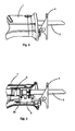
- Figure 2 is a planar view of the assembled elements of Figure 1;
- Figure 3 is a cross sectional view of Figure 2;
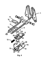
- Figure 4 is an exploded perspective view of a guide shoe of an embodiment of the power saw of the invention;
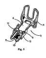
- Figure 5 is a perspective view of the assembled guide shoe of Figure 4;
- Figure 6 is a top view of Figure 5;
- Figure 7 is a cross sectional view along A-A line of Figure 6;
- Figure 8 is a top view of the guide shoe of the present invention in a first position during adjustment;
- Figure 9 is a top view of the guide shoe of the present invention in a second position during adjustment;
- Figure 10 is a top view of the guide shoe of the present invention in a third position during adjustment;
- Figure 11 is a top view of the guide shoe of the present invention in a fourth position during adjustment;
- Figure 12 is a top view of the guide shoe of the present invention in a fifth position during adjustment; and
- Figure 13 is a top view of the guide shoe of the present invention after adjustment is complete.
-
- Referring to Figures 1 to 3, a power saw includes a clam shell housing 1 and a
gear box 2 disposed in the clam shell housing 1. Asaw blade 3 extending beyond the clam shell housing 1 is attached to thegear box 2 and is reciprocatively driven by a motor (not shown) for cutting a workpiece. Aguide shoe 5 mounted on thegear box 2 within the clam shell housing 1 is pivotally connected to anexterior guide plate 4. - Referring to Figures 4 to 7, the
guide shoe 5 includes asupport plate 6 which is pivotally connected at its first end to theguide plate 4 and which is partially nested near to its second end within a bracket assembly 7. Apush plate 8 is slidably disposed between thesupport plate 6 and the bracket assembly 7. Extending from the second end of thesupport plate 6 is anelongate slot 11 which is open-ended (ie a substantially U-shaped slot). A plurality ofadjacent slide notches 12 are formed along an inner edge of theelongate slot 11. Each of theslide notches 12 communicates with theelongate slot 11. Anarcuate face 120 is formed in eachslide notch 12 and a central angle corresponding to thearcuate face 120 is less than 180 degrees. - The bracket assembly 7 includes a fixed
bracket 13 and abar member 14. The fixedbracket 13 adopts a substantially U-shaped configuration with abottom plate 15 and a pair offlanges 16 extending upwardly from opposite edges of thebottom plate 15. Thebottom plate 15 defines afirst slot 17. Eachflange 16 defines a latchingslot 18 and throughholes 28 on opposite sides of the latchingslot 18. Thebar member 14 extends between theflanges 16 and is tightly latched in the latchingslots 18.Bolts 30 extend between theflanges 16 and through the throughholes 28 to fix the bracket assembly 7 (and therefore the guide shoe 5) to thegear box 2. - The
bar member 14 defines asecond slot 19. Aslide pin 9 extends between thefirst slot 17 and thesecond slot 19. The width of thefirst slot 17 and the width of thesecond slot 19 are substantially equal to the diameter of theslide pin 9. Accordingly, theslide pin 9 can only move along the length of thebar member 14 in a direction substantially perpendicular to the direction of receiprocative movement of thesaw blade 3. - The
push plate 8 defines a receivingslot 20. Theslide pin 9 extends through the receivingslot 20 and engages acoaxial slide notch 12. The receivingslot 20 includes a first receivingportion 21 and a second receivingportion 22 communicating with the first receivingportion 21 in a substantially L-shaped configuration. The length of the first receivingportion 21 in the direction of movement of the slide pin 9 (ie substantially perpendicular to the direction of reciprocative movement of the saw blade 3) is greater than the diameter of theslide pin 9 and greater than the sum of the diameter of theslide pin 9 plus the depth of theslide notch 12. The length of the second receivingportion 22 in the direction of movement of the slide pin 9 (ie substantially perpendicular to the direction of movement of the saw blade 3) is substantially equal to the diameter of theslide pin 9. - The
push plate 8 has aguide block 29 on its upper face to guide theslide pin 9. An arcuate guidingface 210 is formed in the first receivingportion 21 adjacent to theguide block 29. A central angle corresponding to thearcuate guiding face 210 is less than 180 degrees. - Adjacent to one end, the
bottom plate 15 defines athird slot 24 which is closed and afirst projection 25 projects inwardly from an edge of thethird slot 24. Asecond projection 26 projects outwardly from an end of thepush plate 8. Atorsion spring 10 is received in thethird slot 24 and its first end is fixed to thefirst projection 25 and its second end is fixed to thesecond projection 26. - The
guide shoe 5 has a first working state (or locking state) and a second working state (or release state). When theguide shoe 5 is in the first working state, theslide pin 9 is latched in the second receivingportion 22 of the receivingslot 20 and engaged with theslide notch 12 at the same time so that theguide plate 4 is immovable with respect to thesaw blade 3. When theguide shoe 5 is in the second working state, theslide pin 9 is fully disengaged from theslide notch 12 and relocates onto a joiningface 122 betweenadjacent slide notches 12 so that theguide plate 4 is freely adjustable. - The adjustment of the
guide shoe 5 between the first and second working states will now be described in detail with reference to Figures 8 to 13. When theguide shoe 5 is to be adjusted from the first working state, the user pushes thepush plate 8 inwardly (Figure 8) against the force of thespring 10 and the first receivingportion 21 moves into contact with theslide pin 9. The user then pulls thesupport plate 6 laterally (whilst still pushing the push plate 8) and theslide pin 9 moves laterally towards thejoint face 122 betweenadjacent slide notches 12 via the drive of the slide notch 12 (Figure 9) so that theguide shoe 5 adopts the second working state (or release state). In this state, theslide pin 9 has reached the arcuate pushingface 210 of the first receiving portion 21 (Figure 10). Referring to Figure 11, when thepush plate 8 and thesupport plate 6 are released by the user, theslide pin 9 is pressed laterally by the slanted force of the pushingface 210 and thepush plate 8 moves laterally (Figure 12) towards anadjacent slide notch 12. Finally, theslide pin 9 is pushed to a position between theadjacent slide notch 12 and theposition block 29 and at the same time is latched into the second receivingportion 22 of the push plate 8 (Figure 13) under the force of thetorsion spring 10. In this way, theguide shoe 5 of the present invention achieves quick adjustment and returns to the first working state.
Claims (10)
- A power saw comprising;wherein the guide shoe (5) has a first working state in which the slide pin (9) is received in the receiving slot (20) and a first of the slide notches (12) so that the guide plate (4) is immovable with respect to the saw blade (3) and a second working state in which the slide pin (9) is disengaged from the first of the slide notches (12) and the guide plate (4) is moveable with respect to the saw blade (3).a clam shell housing (1),a gear box (2) disposed in the clam shell housing (1),a saw blade (3) attached to the gear box (2) for axially reciprocative movement,a guide plate (4) for guiding the saw blade (3) anda guide shoe (5) including:a bracket assembly (7) fixed relative to the gear box (2),a support plate (6) which is partially nested within the bracket assembly (7) and which is pivotally connected to the guide plate (4), the support plate (6) defining axially a plurality of slide notches (12),a push plate (8) slidably disposed between the support plate (6) and the bracket assembly (7), the push plate (8) defining a receiving slot (20),a slide pin (9) extending through the receiving slot (20), the slide pin (9) being selectively engageable with the plurality of slide notches (12), anda resilient member (10) disposed between the bracket assembly (7) and the push plate (8),
- A power saw as claimed in claim 1 wherein the bracket assembly (7) includes a fixed bracket (13) and a bar member (14).
- A power saw as claimed in claim 2 further comprising:wherein the fixed bracket (13) defines a first slot (17) elongated in a direction perpendicular to a direction of the reciprocative movement of the saw blade (3) and the bar member (14) defines a second slot (19) elongated in a direction perpendicular to a direction of the reciprocative movement of the saw blade (3), and wherein a first end and a second end of the slide pin (9) are mounted in the first slot (17) and the second slot (19) respectively whereby to be slidable only in the direction perpendicular to the direction of the reciprocating movement of the blade.a joining member (30) for fixing the fixed bracket (13) to the gear box (2),
- A power saw as claimed in any preceding claim wherein an arcuate face (120) is formed in the slide notch (12) and a central angle corresponding to the arcuate face (120) is less than 180 degrees.
- A power saw as claimed in any preceding claim wherein the support plate (6) defines an elongate slot (11) in communication with each slide notch (12).
- A power saw as claimed in any preceding claim wherein the receiving slot (20) includes a first receiving portion (21) and a second receiving portion (22) in communication with the first receiving portion (21), wherein a length of the first receiving portion (21) in the direction of movement of the slide pin (9) is greater than a diameter of the slide pin (9) and a length of the second receiving portion (22) in the direction of movement of the slide pin (9) is substantial equal to the diameter of the slide pin (9).
- A power saw as claimed in claim 6 wherein an arcuate pushing face (210) is formed in the first receiving portion (21) and a central angle corresponding to the arcuate pushing face (210) is less than 180 degrees.
- A power saw as claimed in claim 6 or 7 wherein in the first working state the slide pin (9) is latched into the second receiving portion (22) and the slide notch (12) at the same time.
- A power saw as claimed in any of claims 6 to 8 wherein the length of the first receiving portion (21) in the direction of movement of the slide pin (9) is larger than the sum of the diameter of the slide pin (9) plus the depth of the slide notch (12).
- A power saw as claimed in claim 9 wherein in the second working state the slide pin (9) is located on a joining face (122) between two adjacent slide notches (12).
Applications Claiming Priority (2)
| Application Number | Priority Date | Filing Date | Title |
|---|---|---|---|
| CNU2003201106034U CN2701563Y (en) | 2003-10-31 | 2003-10-31 | Electric knife saws |
| CN200320110603 | 2003-10-31 |
Publications (1)
| Publication Number | Publication Date |
|---|---|
| EP1527837A1 true EP1527837A1 (en) | 2005-05-04 |
Family
ID=34398373
Family Applications (1)
| Application Number | Title | Priority Date | Filing Date |
|---|---|---|---|
| EP04256723A Withdrawn EP1527837A1 (en) | 2003-10-31 | 2004-10-29 | Adjustable guide plate for reciprocating saw |
Country Status (2)
| Country | Link |
|---|---|
| EP (1) | EP1527837A1 (en) |
| CN (1) | CN2701563Y (en) |
Cited By (5)
| Publication number | Priority date | Publication date | Assignee | Title |
|---|---|---|---|---|
| GB2424616A (en) * | 2005-03-28 | 2006-10-04 | Milwaukee Electric Tool Corp | A power tool with recessed support shoe |
| EP1911539A1 (en) * | 2006-10-12 | 2008-04-16 | HILTI Aktiengesellschaft | Electric hacksaw with shielding element |
| GB2443073A (en) * | 2006-10-16 | 2008-04-23 | Chervon Ltd | An adjustable support shoe for a reciprocating saw |
| US20130333231A1 (en) * | 2012-06-14 | 2013-12-19 | Milwaukee Electric Tool Corporation | Reciprocating saw with adjustable shoe |
| CN114619098A (en) * | 2020-12-11 | 2022-06-14 | 喜利得股份公司 | Reciprocating tool |
Families Citing this family (2)
| Publication number | Priority date | Publication date | Assignee | Title |
|---|---|---|---|---|
| CN101642831B (en) * | 2008-08-06 | 2011-12-07 | 苏州宝时得电动工具有限公司 | Reciprocating saw |
| CN104097234A (en) * | 2013-04-07 | 2014-10-15 | 天佑电器(苏州)有限公司 | Reciprocating saw |
Citations (4)
| Publication number | Priority date | Publication date | Assignee | Title |
|---|---|---|---|---|
| US5007172A (en) * | 1990-06-13 | 1991-04-16 | Milwaukee Electric Tool Corporation | Quick change guide shoe |
| EP0669181A1 (en) * | 1994-02-23 | 1995-08-30 | S-B Power Tool Company | Adjustable guide shoe for reciprocating saw |
| US6272757B1 (en) * | 1999-07-22 | 2001-08-14 | S-B Power Tool Company | Adjustable guide shoe for reciprocating saw |
| JP2002052503A (en) * | 2000-08-07 | 2002-02-19 | Makita Corp | Shoe-fixing device of reciprocative cutting tool |
-
2003
- 2003-10-31 CN CNU2003201106034U patent/CN2701563Y/en not_active Expired - Lifetime
-
2004
- 2004-10-29 EP EP04256723A patent/EP1527837A1/en not_active Withdrawn
Patent Citations (4)
| Publication number | Priority date | Publication date | Assignee | Title |
|---|---|---|---|---|
| US5007172A (en) * | 1990-06-13 | 1991-04-16 | Milwaukee Electric Tool Corporation | Quick change guide shoe |
| EP0669181A1 (en) * | 1994-02-23 | 1995-08-30 | S-B Power Tool Company | Adjustable guide shoe for reciprocating saw |
| US6272757B1 (en) * | 1999-07-22 | 2001-08-14 | S-B Power Tool Company | Adjustable guide shoe for reciprocating saw |
| JP2002052503A (en) * | 2000-08-07 | 2002-02-19 | Makita Corp | Shoe-fixing device of reciprocative cutting tool |
Non-Patent Citations (1)
| Title |
|---|
| PATENT ABSTRACTS OF JAPAN vol. 2002, no. 06 4 June 2002 (2002-06-04) * |
Cited By (8)
| Publication number | Priority date | Publication date | Assignee | Title |
|---|---|---|---|---|
| GB2424616A (en) * | 2005-03-28 | 2006-10-04 | Milwaukee Electric Tool Corp | A power tool with recessed support shoe |
| EP1911539A1 (en) * | 2006-10-12 | 2008-04-16 | HILTI Aktiengesellschaft | Electric hacksaw with shielding element |
| GB2443073A (en) * | 2006-10-16 | 2008-04-23 | Chervon Ltd | An adjustable support shoe for a reciprocating saw |
| GB2443073B (en) * | 2006-10-16 | 2011-03-02 | Chervon Ltd | Adjusting Mechanism for A Support Shoe for a Reciprocating Saw |
| US20130333231A1 (en) * | 2012-06-14 | 2013-12-19 | Milwaukee Electric Tool Corporation | Reciprocating saw with adjustable shoe |
| US9421625B2 (en) * | 2012-06-14 | 2016-08-23 | Milwaukee Electric Tool Corporation | Reciprocating saw with adjustable shoe |
| CN114619098A (en) * | 2020-12-11 | 2022-06-14 | 喜利得股份公司 | Reciprocating tool |
| US12465983B2 (en) | 2020-12-11 | 2025-11-11 | Hilti Aktiengesellschaft | Reciprocating tool |
Also Published As
| Publication number | Publication date |
|---|---|
| CN2701563Y (en) | 2005-05-25 |
Similar Documents
| Publication | Publication Date | Title |
|---|---|---|
| US6272757B1 (en) | Adjustable guide shoe for reciprocating saw | |
| US7204026B2 (en) | Adjustable reciprocating saw | |
| CN100352629C (en) | Reciprocating saw | |
| US9701035B2 (en) | Adjustable locking shoe | |
| EP1884304A1 (en) | Bearing for a reciprocating shaft of a reciprocating saw | |
| US7963043B2 (en) | Support shoe for a reciprocating saw | |
| US9592623B2 (en) | Rip fence having dual adjustment for a power tool | |
| US7526867B2 (en) | Tool with clamping apparatus and an improved scrolling mechanism | |
| US20110010951A1 (en) | Locking shoe for reciprocating saw | |
| US8104386B2 (en) | Quick release device for saw blade guard assembly in a circular saw and saw blade guard assembly using the same | |
| US20250303601A1 (en) | Power Tool Accessories for Cutting Elongated Members | |
| US20060090348A1 (en) | Power saw | |
| WO2018001385A1 (en) | Cutting tool | |
| US7210232B2 (en) | Saw blade clamping mechanism for a power tool | |
| JP4600184B2 (en) | Guide and portable cutting tool provided with the same | |
| EP2591887B1 (en) | Electric power tool | |
| US3470923A (en) | Adjustable dual blade notching saw | |
| EP4245488A1 (en) | Workpiece clamp assembly | |
| WO2019047951A1 (en) | Electric saw | |
| CN1978111B (en) | Electrically operated hand-held reciprocating saws and their blade clamping devices | |
| US5706874A (en) | Biscuit joiner | |
| US20020189109A1 (en) | Circular saw cutting aid for non-standard cuts | |
| EP1625921B1 (en) | Portable pocket cutter | |
| CN218659604U (en) | Cutting tool and guide attachment | |
| CN223862953U (en) | Universal jig for circular sawing machine |
Legal Events
| Date | Code | Title | Description |
|---|---|---|---|
| PUAI | Public reference made under article 153(3) epc to a published international application that has entered the european phase |
Free format text: ORIGINAL CODE: 0009012 |
|
| AK | Designated contracting states |
Kind code of ref document: A1 Designated state(s): AT BE BG CH CY CZ DE DK EE ES FI FR GB GR HU IE IT LI LU MC NL PL PT RO SE SI SK TR |
|
| AX | Request for extension of the european patent |
Extension state: AL HR LT LV MK |
|
| AKX | Designation fees paid | ||
| REG | Reference to a national code |
Ref country code: DE Ref legal event code: 8566 |
|
| STAA | Information on the status of an ep patent application or granted ep patent |
Free format text: STATUS: THE APPLICATION IS DEEMED TO BE WITHDRAWN |
|
| 18D | Application deemed to be withdrawn |
Effective date: 20051105 |