EP1527822B1 - Dispensing device with two pumps comprising flexible pump chambers - Google Patents
Dispensing device with two pumps comprising flexible pump chambers Download PDFInfo
- Publication number
- EP1527822B1 EP1527822B1 EP03425708A EP03425708A EP1527822B1 EP 1527822 B1 EP1527822 B1 EP 1527822B1 EP 03425708 A EP03425708 A EP 03425708A EP 03425708 A EP03425708 A EP 03425708A EP 1527822 B1 EP1527822 B1 EP 1527822B1
- Authority
- EP
- European Patent Office
- Prior art keywords
- dispensing
- frame
- pumping
- swirling
- membrane
- Prior art date
- Legal status (The legal status is an assumption and is not a legal conclusion. Google has not performed a legal analysis and makes no representation as to the accuracy of the status listed.)
- Expired - Lifetime
Links
Images


Classifications
-
- B—PERFORMING OPERATIONS; TRANSPORTING
- B05—SPRAYING OR ATOMISING IN GENERAL; APPLYING FLUENT MATERIALS TO SURFACES, IN GENERAL
- B05B—SPRAYING APPARATUS; ATOMISING APPARATUS; NOZZLES
- B05B1/00—Nozzles, spray heads or other outlets, with or without auxiliary devices such as valves, heating means
- B05B1/34—Nozzles, spray heads or other outlets, with or without auxiliary devices such as valves, heating means designed to influence the nature of flow of the liquid or other fluent material, e.g. to produce swirl
- B05B1/3405—Nozzles, spray heads or other outlets, with or without auxiliary devices such as valves, heating means designed to influence the nature of flow of the liquid or other fluent material, e.g. to produce swirl to produce swirl
- B05B1/341—Nozzles, spray heads or other outlets, with or without auxiliary devices such as valves, heating means designed to influence the nature of flow of the liquid or other fluent material, e.g. to produce swirl to produce swirl before discharging the liquid or other fluent material, e.g. in a swirl chamber upstream the spray outlet
-
- B—PERFORMING OPERATIONS; TRANSPORTING
- B05—SPRAYING OR ATOMISING IN GENERAL; APPLYING FLUENT MATERIALS TO SURFACES, IN GENERAL
- B05B—SPRAYING APPARATUS; ATOMISING APPARATUS; NOZZLES
- B05B11/00—Single-unit hand-held apparatus in which flow of contents is produced by the muscular force of the operator at the moment of use
- B05B11/01—Single-unit hand-held apparatus in which flow of contents is produced by the muscular force of the operator at the moment of use characterised by the means producing the flow
- B05B11/10—Pump arrangements for transferring the contents from the container to a pump chamber by a sucking effect and forcing the contents out through the dispensing nozzle
- B05B11/1028—Pumps having a pumping chamber with a deformable wall
- B05B11/1032—Pumps having a pumping chamber with a deformable wall actuated without substantial movement of the nozzle in the direction of the pressure stroke
-
- B—PERFORMING OPERATIONS; TRANSPORTING
- B05—SPRAYING OR ATOMISING IN GENERAL; APPLYING FLUENT MATERIALS TO SURFACES, IN GENERAL
- B05B—SPRAYING APPARATUS; ATOMISING APPARATUS; NOZZLES
- B05B11/00—Single-unit hand-held apparatus in which flow of contents is produced by the muscular force of the operator at the moment of use
- B05B11/01—Single-unit hand-held apparatus in which flow of contents is produced by the muscular force of the operator at the moment of use characterised by the means producing the flow
- B05B11/10—Pump arrangements for transferring the contents from the container to a pump chamber by a sucking effect and forcing the contents out through the dispensing nozzle
- B05B11/1028—Pumps having a pumping chamber with a deformable wall
- B05B11/1033—Pumps having a pumping chamber with a deformable wall the deformable wall, the inlet and outlet valve elements being integrally formed, e.g. moulded
-
- B—PERFORMING OPERATIONS; TRANSPORTING
- B05—SPRAYING OR ATOMISING IN GENERAL; APPLYING FLUENT MATERIALS TO SURFACES, IN GENERAL
- B05B—SPRAYING APPARATUS; ATOMISING APPARATUS; NOZZLES
- B05B11/00—Single-unit hand-held apparatus in which flow of contents is produced by the muscular force of the operator at the moment of use
- B05B11/01—Single-unit hand-held apparatus in which flow of contents is produced by the muscular force of the operator at the moment of use characterised by the means producing the flow
- B05B11/10—Pump arrangements for transferring the contents from the container to a pump chamber by a sucking effect and forcing the contents out through the dispensing nozzle
- B05B11/1042—Components or details
- B05B11/1052—Actuation means
- B05B11/1056—Actuation means comprising rotatable or articulated levers
- B05B11/1057—Triggers, i.e. actuation means consisting of a single lever having one end rotating or pivoting around an axis or a hinge fixedly attached to the container, and another end directly actuated by the user
-
- B—PERFORMING OPERATIONS; TRANSPORTING
- B05—SPRAYING OR ATOMISING IN GENERAL; APPLYING FLUENT MATERIALS TO SURFACES, IN GENERAL
- B05B—SPRAYING APPARATUS; ATOMISING APPARATUS; NOZZLES
- B05B11/00—Single-unit hand-held apparatus in which flow of contents is produced by the muscular force of the operator at the moment of use
- B05B11/01—Single-unit hand-held apparatus in which flow of contents is produced by the muscular force of the operator at the moment of use characterised by the means producing the flow
- B05B11/10—Pump arrangements for transferring the contents from the container to a pump chamber by a sucking effect and forcing the contents out through the dispensing nozzle
- B05B11/1081—Arrangements for pumping several liquids or other fluent materials from several containers, e.g. for mixing them at the moment of pumping
- B05B11/1084—Arrangements for pumping several liquids or other fluent materials from several containers, e.g. for mixing them at the moment of pumping each liquid or other fluent material being pumped by a separate pump
- B05B11/1085—Arrangements for pumping several liquids or other fluent materials from several containers, e.g. for mixing them at the moment of pumping each liquid or other fluent material being pumped by a separate pump the pumps being coaxial
-
- B—PERFORMING OPERATIONS; TRANSPORTING
- B05—SPRAYING OR ATOMISING IN GENERAL; APPLYING FLUENT MATERIALS TO SURFACES, IN GENERAL
- B05B—SPRAYING APPARATUS; ATOMISING APPARATUS; NOZZLES
- B05B7/00—Spraying apparatus for discharge of liquids or other fluent materials from two or more sources, e.g. of liquid and air, of powder and gas
- B05B7/02—Spray pistols; Apparatus for discharge
- B05B7/04—Spray pistols; Apparatus for discharge with arrangements for mixing liquids or other fluent materials before discharge
- B05B7/0408—Spray pistols; Apparatus for discharge with arrangements for mixing liquids or other fluent materials before discharge with arrangements for mixing two or more liquids
Definitions
- the object of the present invention is a dispensing device for the concurrent dispensing of two or more fluids separately kept in a tank.
- Such need is generally related to the need of combining the two fluids only on the surface to be cleaned, due to the deleterious effects that the combination of such fluids would cause to the structure of the device.
- such need is related to the need of keeping the two fluids separate into the tank, for proper storage, combining.them upon dispensing or a few seconds before that.
- Some dispensing devices known in the field provide for the concurrent dispensing of two fluids kept separate in a tank.
- Object of the present invention is that of providing to the realisation of a dispensing device which should meet the above requirements and at the same time overcome the disadvantages mentioned above with reference to the prior art.
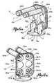
- . - figure 1 shows an axonometric view with separate parts of a dispensing device according to an embodiment
- - figures 2a and 2b show axonometric views of the dispensing device
- - figures 3a - 3c respectively show a front, a side and a plan view of the dispensing device
- FIG. 4 shows a section view of the dispensing device according to the section line IV - IV in figure 3c;
- - figures 5a and 5b show axonometric views of a trigger of the dispensing device
- - figures 6a and 6b show axonometric views of a frame of the dispensing device
- - figures 7a and 7b show axonometric views of a membrane of the dispensing device
- - figures 8a and 8b show axonometric views of a counter frame of the dispensing device
- FIG. 9a and 9b show axonometric views of a mask of swirling means of the dispensing device
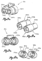
- FIG. 10a and 10b show axonometric views of tubular swirling elements of the swirling means of the dispensing device
- FIG. 11 shows a section detail of the swirling means
- FIG. 12 shows an axonometric view with separate parts of the dispensing device according to a further embodiment
- FIG. 13 shows a section view of the dispensing device of figure 12
- FIG. 14a and 14b show axonometric views of the swirling means of a further variant of embodiment
- FIG. 15a and 15b show axonometric views of a mask of the swirling means of figures 14a and 14b.
- reference numeral 1 generally indicates a dispensing device according to a variant of embodiment.
- the dispensing device 1 is associable to a tank (not shown) adapted for the separate containment of a first fluid and a second fluid.
- said tank comprises at least two containment chambers, respectively adapted for the containment of said fluids.
- device 1 is fluidically associable to said tank by a first feeding pipe 10a and a second feeding pipe 10b, respectively in fluidic communication with said first containment chamber and said second containment chamber of the tank.
- the dispensing device 1 is mechanically associable to said tank by closing means 20.
- the dispensing device 1 comprises actuating means 40 suitable for the actuation of said device for the concurrent dispensing of the first and of the second fluid.
- said device comprises pumping means 60, adapted for sucking said fluids from the tank and dispensing towards an environment outside the device, for example a surface to be cleaned.
- the dispensing device 1 further comprises swirling means 200, adapted for imparting a desired swirling to said first and second fluid, for example in order to better spread on the surface to be cleaned or to better mix on it or in a mixing chamber.
- the dispensing device 1 comprises covering means 300, adapted for covering said pumping means 60 and/or for improving the device's grip by the user.
- the closing means 20 comprises a closure 22 realised by an annular wall 24 having a preferably knurled outside surface, in order to help the grip of closure 22 by the user (figure 4).
- closure 22 exhibits a threaded portion 26 for connecting closure 22 to the tank.
- closure 22 exhibits means for connecting device 1 to closure 22, for example comprising a snap mechanism 28.
- said closing means 20 comprises a circular plate 29, preferably made of foamed material, associable to closure 22, for example at the threaded portion 26, substantially having a sealing function between closure 22 and the containment chambers of said fluids.
- the circular plate 29 exhibits a first thorough opening 30a and a second thorough opening 30b, respectively provided for inserting the first pipe 10a and the second pipe 10b.
- Said circular plate 29 further comprises through openings 30c, 30d, each in fluid communication with the fluid containment chambers.
- the dispensing device comprises a venting membrane 32, permeable to gases and impermeable to fluids, preferably a Gore® membrane.
- the actuating means 40 comprises a trigger 42, that is an element, generally elongated, hingeable and affectable by the user's hand fingers, for actuating the dispensing device 1 (figures 5a, 5b).
- trigger 42 comprises a handling portion 44, upon which the user acts, and an actuation portion 46, operatively associable to the pumping means 60 of device 1 for fluid dispensing.
- said actuation portion 46 comprises a first actuation pin 48a and a second actuation pin 48b, projecting from said handling portion 44.
- trigger 42 comprises an arm 50, projecting from said handling portion 44, carrying an hinging pin 52 at a free end of said arm.
- said arm 50 projects from said handling portion 44 at least partly overhanging said actuation portion 46.
- the pumping means 60 of device 1 comprises a frame 62, preferably made in a single piece (figures 6a, 6b).
- frame 62 comprises a frame plate 64, generally rectangular, from which a first tubular delivery element 66a and a second tubular delivery element 66b protrude, which respectively develop along a dispensing axis X-X.
- said dispensing axis X-X is perpendicular to the frame plate 64.
- frame 62 exhibits respective delivery chambers 68a, 68b.
- Each tubular delivery element 66a, 66b is in fluid communication with the respective delivery chamber 68a, 68b by a respective delivery opening 70a, 70b.
- Each delivery opening 70a, 70b is surrounded, in said delivery chamber 68a, 68b, by a respective annular wall of delivery opening 72a, 72b.
- said frame 62 comprises a first tubular intake element 74a and a second tubular intake element 74b.
- Said tubular intake elements respectively exhibit an elbow portion 76a, 76b connected to an end intake portion 78a, 78b.
- Said end intake portions 78a, 78b develop along an intake axis Y-Y, preferably perpendicular to said dispensing axis X-X.
- intake chambers 80a, 80b At the union between said tubular intake elements 74a, 74b with the frame plate 64, there are preferably arranged intake chambers 80a, 80b.
- Said tubular intake elements 74a, 74b are in fluid communication with said intake chambers 80a, 80b by respective intake chamber openings 82a, 82b.
- Said intake chamber openings 82a, 82b are surrounded in said intake chambers 80a, 80b by respective annular walls of intake chamber openings 84a, 84b.
- frame 62 comprises a connecting plate 88, arranged at the free end of said tubular intake elements 74a, 74b.
- said connecting plate exhibits at least one venting opening 89, passing through said plate.
- said frame comprises a connecting wall 90 that protrudes from the frame plate 64, along its edge, from a side opposed to said tubular delivery elements 66a, 66b.
- the pumping means 60 further comprises a membrane 100, preferably made in a single piece (figures 7a, 7b).
- Membrane 100 comprises a membrane plate 102 from which a first pumping element 104a and a second pumping element 104b protrude, realised by elements preferably shaped as truncated cones and hollow.
- the pumping means 60 further comprises valve delivery means 106, adapted for preventing the reflow of the first and of the second dispensed fluid.
- valve delivery means 106 respectively comprises for the first and the second fluid, an annular wall of delivery means 108a, 108b that surround respective openings of delivery means 110a, 110b of the membrane plate 102 of membrane 100.
- said delivery means 106 comprises respective cap elements 112a, 112b, provided, according to a preferred embodiment, with a ring 114a, 114b arranged on top of said cap elements.
- the dispensing device 1 further comprises check valve means 116, adapted for preventing the reflow of the first and of the second fluid sucked towards the tank.
- said check valve means 116 respectively comprises a lip 118a, 118b of the membrane plate 102.
- respective notches of the membrane plate 102 realise in said plate said lips 118a, 118b.
- the pumping elements 104a, 104b of membrane 100 are arranged in intermediate position between said valve delivery means 106 and said check valve means 116.
- Membrane 100 further comprises an annular membrane wall 120 that protrudes from the membrane plate 102, along its edge and from a side opposed to pumping elements.
- membrane 100 exhibits respective partitions 122a, 122b, protruding from the membrane plate 102 from a side opposed to said pumping elements 104a, 104b.
- the first partition 122a surrounds a group consisting of the first pumping element 104a, of the first opening of the valve delivery means 110a and of the first lip 118a of the check valve means.
- the second partition 122b surrounds a group consisting of the second pumping element 104b, of the second opening of the valve delivery means 110b and of the second lip 118b of the check valve means.
- the pumping means 60 further comprises a counter frame 130, preferably made in a single piece (figures 8a, 8b).
- the counter frame 130 comprises a counter frame plate 132 from which, in an embodiment, respective projections 134a, 134b, arranged sided and separate, protrude.
- each of said projections 134a, 134b exhibits a projection 136a, 136b, preferably protruding from said projection.
- the counter frame 130 further comprises respective annular counter frame walls 138a, 138b, protruding from the same side as said projections 134a, 134b.
- a counter frame arm 140 protrudes from said counter frame plate 132, which at a free end exhibits a hinge seat 142.
- said counter frame arm 140 projects from said counter frame plate 132 from the same side as said projections 134a, 134b.
- counter frame 130 exhibits an annular counter frame wall 144, projecting from said counter frame plate 132 from the same side as said projections 134a, 134b.
- the swirling means 200 comprises a first tubular swirling element 202a and a second tubular swirling element 202b (figures 9a, 9b, 10a, 10b and 11).
- Each tubular swirling element 202a, 202b comprises a connecting portion 204a, 204b and an active portion 206a, 206b.
- Said active portion 206a, 206b exhibits an inside arm 208a, 208b integral with the respective connecting portion 204a, 204b by a swirling plate 210a, 210b, provided with arm openings 212a, 212b.
- each inside arm 208a, 208b exhibits at least one swirling projection 214a, 214b.
- Said swirling projections are preferably arranged circumferentially at the free end of the swirling arm, spaced out by swirling notches 216a, 216b.
- said swirling means 200 comprises a mask 220 provided with connecting walls 222a, 222b to said tubular swirling elements 202a, 202b.
- said mask 220 exhibits respective swirling walls 224a, 224b, each provided with a dispensing opening, 226b.
- the first pipe 10a and the second pipe 10b are respectively inserted in the first thorough opening 30a and in the second thorough opening 30b of the circular plate 29 of the closing means 20.
- Said plate is arranged inside said closure 22, preferably at the end of the threaded portion 26, adjacent the snap mechanism 28.
- the venting membrane 32 is made integral with frame 62, preferably at the surface of the connecting plate 88 of frame 62 that faces the interior of the containment chambers.
- said venting membrane 32 is welded to the connecting plate 88 so as to cover the venting openings 89 presents in said plate.
- Frame 62 of the pumping means 60 is arranged on the circular plate 29, so that the connecting plate 88 of said frame is connected to closure 22 by the snap mechanism 28.
- the first pipe 10a is in fluid communication with the first tubular intake element 74a and the second pipe 10b is in fluid communication with the second tubular intake element 74b.
- Membrane 100 of the pumping means 60 is associated to frame 62.
- the membrane plate 102 is adapted for being coupled to the frame plate 64 and surrounded by the connecting wall 90 projecting from said frame plate 64.
- the pumping elements 104a, 104b are respectively inserted into the insertion openings 86a, 86b of the frame plate 64.
- valve delivery means 108a, 108b of membrane 100 couple with the respective delivery chambers 68a, 68b of frame 62.
- said coupling makes rings 114a, 114b of the cap elements 112a, 112b introduce into the respective delivery openings 70a, 70b, insisting on the respective annular delivery opening walls 72a, 72b.
- the annular walls of the check valve means 120a, 120b couple with the respective intake chambers 80a, 80b.
- each lip 118a, 118b of membrane 100 couples with the respective intake opening 82a, 82b, abutting against the respective intake opening wall 84a, 84b.
- the counter frame 130 is adapted for associating to frame 62 so that membrane 100 appears as an intermediate element blocked between said frame and said counter frame.
- the connecting wall 90 of the frame plate 64 couples with the annular wall of the counter frame plate 144, for example with a snap connection.
- Projections 134a, 134b of the counter frame 130 are arranged at the check valve means, whereas the respective projections 136a, 136b penetrate, at least partly, into the volume defined by the pumping elements 104a, 104b.
- said first pumping chamber and said second pumping chamber are separate because said flow partitions after assembly insert between projections 134a, 134b of the counter frame 130.
- Said pumping chambers respectively are in fluid communication through a duct called intake duct, with the first containment chamber and the second containment chamber of the tank.
- said intake ducts comprise said tubular intake elements 74a, 74b of frame 62 and said pipes 10a, 10b.
- said pumping chambers respectively are in fluid communication through a duct, called delivery duct, with the exterior of the dispensing device.
- valve delivery means 106 Between said pumping chambers and said environment outside the dispensing device 1, along said dispensing ducts, there are provided said valve delivery means 106.
- cap elements 112a, 112b of said valve delivery means 106 are respectively inserted into the annular counter frame walls 138a, 138b of said counter frame.
- the counter frame arm 140 protruding from the counter frame plate 132, is adapted for hinging trigger 42 of the actuation means 40.
- the hinging pin 52 carried by arm 50 of trigger 42, is operatively coupled with the hinge seat 142 of the counter frame arm 140, realising a hinge for said trigger.
- the actuation means 40 is arranged in suitable position for affecting the pumping means for fluid dispensing.
- said actuation pins 48a, 48b of the actuation portion 46 of trigger 42 can abut against the respective pumping elements 104a, 104b of the pumping means 60.
- tubular delivery elements 66a, 66b of frame 62 is associated to the respective tubular swirling elements 202a, 202b.
- the connecting portion 204a, 204b of said tubular swirling elements associate to said free ends, for example by a snap connection.
- tubular delivery elements are moved in abutment with their free end with the swirling plates 210a, 210b of said swirling means.
- Said tubular delivery elements 66a, 66b remain in fluid communication with the exterior of the dispensing device thanks to the openings of arm 212a, 212b provided on each swirling plate 210a, 210b.
- Mask 220 of the swirling means 200 is adapted for being associated to said tubular swirling elements 202a, 202b.
- the connecting walls 222a, 222b of said mask 220 are coupled the active portion 206a, 206b of the tubular swirling elements 202a, 202b.
- the volume comprised between the inside arm 208a, 208b, the active portion 206a, 206b and the swirling plate 210a, 210b of the tubular swirling element 202a, 202b and the swirling wall 224a, 224b of mask 220 defines an intermediate chamber.
- the volume comprised between the free end of the inside arm 208a, 208b, the swirling projections 214a, 214b of the tubular swirling element 202a, 202b and the swirling wall 224a, 224b of mask 220 defines an end swirling chamber.
- Said intermediate chamber and said end swirling chamber are in fluid communication by notches 216a, 216b of the inside arms 208a, 208b.
- the delivery duct between the pumping chambers and the outside environment comprises a swirling duct, said swirling duct comprising an intermediate chamber and an end swirling chamber, in fluid communication with the outside environment through a dispensing opening 226a, 226b of mask 220.
- Cover 300 is associated to said dispensing device for covering at least partly said pumping means and/or for facilitating an ergonomic grip of the device by the user.
- the dispensing device is in a rest configuration wherein the pumping elements 104a, 104b are in a non-deformed configuration, that is, in a configuration wherein the pumping chambers exhibit a maximum volume.
- the user grips said device, for example arranging the rear side of cover 300 in contact with the hand's palm and the fingers on the handling portion 44 of trigger 42.
- valve delivery means 106 and the check valve means 116 are in a closed configuration.
- said pumping chambers shift from the maximum volume to a volume smaller than the maximum volume, for example a minimum volume, corresponding to the maximum rotation of trigger 42.
- the first and the second fluid separately held in the first pumping chamber and in the second pumping chamber, through the action of the trigger and the deformation of the pumping elements, generate a thrust that moves the valve delivery means in an open configuration, whereas the check valve means are forced into a closed configuration.
- the thrust of the fluids acts on the cap elements 112a, 112b of the valve delivery means, making them collapse.
- annular cap elements moves away from the delivery opening 68a, 68b of frame 62, placing said pumping chambers in fluid communication with the outside.
- the first and the second fluid flow through the dispensing duct to the outside, preferably flowing also through said swirling duct.
- said fluids are separately subject to swirling through the passage through notches 216a, 216b of the inside arms 208a, 208b.
- the fluids are therefore separately dispensed, for example on a surface to be cleaned.
- the thrust to which the fluids held in the pumping chambers are subject pushes lips 118a, 118b of the check valve means against the intake openings 82a, 82b of the intake chambers 80a, 80b, preventing the reflow of said fluids towards the tank containment chambers.
- the pumping elements 104a, 104b that exhibit elastic properties, return to the non-deformed condition.
- the pumping chambers are not in fluid communication with the outside environment, since the dispensing duct is cut out.
- venting membrane 32, the venting openings 89 and openings 30c, 30d of the circular plate 29 made of a foamed material are a preferred example of the venting means, adapted for allowing the gas venting from the containment chambers to the outside of the device.
- said venting means allow degassing the containment chambers following the possible production of undesired gases released by said fluids, as well as a passive venting.
- the trigger action on the pumping elements is opposed by the structure of the dispensing device 1 which provides for membrane 100 arranged in intermediate position between frame 62 and counter frame 130.
- Said trigger action is opposed by the connection between said frame and said counter frame and at the same time, by the connection between the counter frame and the trigger itself.
- Said counter frame arm - trigger connection pushes the counter frame towards the frame and thereby membrane 100 towards the latter.
- Frame 62 keeps membrane 100 into position so that the action of trigger 42 on the pumping elements 104a, 104b is effective.
- Said elements that respectively realise intake ducts and delivery ducts, develop along directions incident with one another, preferably orthogonal.
- Membrane 100 made of a deformable elastic material, exhibits both the pumping elements 104a, 104b, and the check and delivery valve means and the partitions for realising separate pumping chambers for the first and the second fluid.
- the fluids are separately held in the respective containment chambers of tank 1 and dispensed separately in a mixing chamber wherein they are mixed before they are delivered outwards (figures 12, 13, 14a, 14b, 15a, 15b).
- the dispensing device 1 comprises swirling means 400 comprising a mixing element 402 provided with tubular connecting elements 404a, 404b adapted for associating with the free end of the tubular delivery elements, 66b of frame 62.
- Said tubular connecting means exhibit, at a side opposed to the connecting end with said tubular delivery means 66a, 66b, respective ejection openings 406a, 406b, preferably obtained in the front wall 408 of a lining element 410.
- Said front wall 408 further comprises one or more swirling projections 412 separate from one another and preferably arranged circumferentially.
- said projections 412 are flush with the surface of the front wall 408.
- said ejection openings are arranged on said front wall 410 radially externally with respect to said swirling projections 412.
- the swirling means 400 further comprises a mask 414 provided with a blanket 416 adapted for being fitted on said lining element 410, and a swirling wall 417 provided with at least one dispensing opening 418.
- said mask 414 exhibits, in a preferred embodiment, at least one notch realised inside the swirling wall 417, having substantially radial extension relative to said mask.
- said swirling wall 417 exhibits a pair of notches 420a, 420b realised inside the swirling wall 417.
- the fluids to be dispensed, separately, are pushed, during the dispensing step, inside the tubular connecting elements 404a, 404b, from which they exit into the swirling chamber.
- the fluids mix both freely and by action of the swirling realised by the projections of the front wall.
- the mixed fluid is dispensed out of the dispensing device.
- mask 414 is in a first open position, wherein notches 420a, 420b are overlapped, at least partly, to openings 406a, 406b of the mixing element 402.
- openings 406a, 406b are in fluid communication with projections 412 by said notches 420a, 420b, so the fluids come out.
- mask 414 is in a second closed position, wherein notches 420a, 420b are not overlapped to openings 406a, 406b of the mixing element 402.
- openings 406a, 406b are not in fluid communication with projections 412, so fluid dispensing is prevented.
- the dispensing device for two or more fluids separately kept in a tank according to the present invention exhibits a reduced number of components.
- the dispensing device according to the present invention exhibits components each having multiple functions, so as to reduce the number of necessary components.
- the membrane is made of a deformable elastic material and realises means for changing the volume of the pumping chambers, elastic return means and, coupled with the counter frame, it delimits said pumping chambers.
- said membrane integrates check and delivery valve means.
- the frame comprises the tubular delivery and intake elements and effectively supports the membrane for opposing the trigger action on the pumping elements.
- the device is provided with intake and delivery ducts having extension along incident directions, preferably perpendicular, in order to allow an easy assembly and convenient use of the trigger.
- the membrane is held between the frame and the counter frame, the latter being connected to the trigger and being pushed towards the membrane during dispensing.
- the frame, the membrane and the counter frame can be coupled in a sequence according to a single coupling direction that overlaps them.
- the assembly of device 1 is quick and accurate.
Abstract
Description
- . The object of the present invention is a dispensing device for the concurrent dispensing of two or more fluids separately kept in a tank.
- . In the field of dispensing devices, in particular intended for household purposes, for example dispensing detergent fluids, there is the need of having devices suitable for the concurrent dispensing of two or more fluids kept separately in a tank.
- . Such need is generally related to the need of combining the two fluids only on the surface to be cleaned, due to the deleterious effects that the combination of such fluids would cause to the structure of the device.
- . Or, such need is related to the need of keeping the two fluids separate into the tank, for proper storage, combining.them upon dispensing or a few seconds before that.
- . Some dispensing devices known in the field provide for the concurrent dispensing of two fluids kept separate in a tank.
- . However, such constructions are clearly derived from a simple coupling of two dispensing devices, each suitable for dispensing a single fluid, actuated by a single trigger.
- . An embodiment according to the description above is shown, for example, in document EP0715899. Moreover, such devices are disclosed in documents WO 97/27121 and DE 197 38 039.
- . There is therefore the need of having a dispensing device for the concurrent dispensing of two or more fluids kept separately in a tank which should be designed for such precise purpose and which should therefore provide for a limited number of components and an optimum operation.
- . Object of the present invention is that of providing to the realisation of a dispensing device which should meet the above requirements and at the same time overcome the disadvantages mentioned above with reference to the prior art.
- . The problem at the basis of the present invention is solved by a dispensing device according to
claim 1. The dependent claims describe variants of embodiments. - . The features and the advantages of the dispensing device according to the present invention will appear more clearly from the following exemplificative and non-limiting description, made with reference to the attached figures, wherein:
- . - figure 1 shows an axonometric view with separate parts of a dispensing device according to an embodiment;
- . - figures 2a and 2b show axonometric views of the dispensing device;
- . - figures 3a - 3c respectively show a front, a side and a plan view of the dispensing device;
- . - figure 4 shows a section view of the dispensing device according to the section line IV - IV in figure 3c;
- . - figures 5a and 5b show axonometric views of a trigger of the dispensing device;
- . - figures 6a and 6b show axonometric views of a frame of the dispensing device;
- . - figures 7a and 7b show axonometric views of a membrane of the dispensing device;
- . - figures 8a and 8b show axonometric views of a counter frame of the dispensing device;
- . - figures 9a and 9b show axonometric views of a mask of swirling means of the dispensing device;
- . - figures 10a and 10b show axonometric views of tubular swirling elements of the swirling means of the dispensing device;
- . - figure 11 shows a section detail of the swirling means;
- . - figure 12 shows an axonometric view with separate parts of the dispensing device according to a further embodiment;
- . - figure 13 shows a section view of the dispensing device of figure 12;
- . - figures 14a and 14b show axonometric views of the swirling means of a further variant of embodiment;
- . - figures 15a and 15b show axonometric views of a mask of the swirling means of figures 14a and 14b.
- . With reference to figures 1, 2a, 2b and 3a - 3c,
reference numeral 1 generally indicates a dispensing device according to a variant of embodiment. - . The
dispensing device 1 is associable to a tank (not shown) adapted for the separate containment of a first fluid and a second fluid. Preferably, said tank comprises at least two containment chambers, respectively adapted for the containment of said fluids. - . In a preferred embodiment,
device 1 is fluidically associable to said tank by afirst feeding pipe 10a and asecond feeding pipe 10b, respectively in fluidic communication with said first containment chamber and said second containment chamber of the tank. - . The
dispensing device 1 is mechanically associable to said tank byclosing means 20. - . The
dispensing device 1 comprises actuating means 40 suitable for the actuation of said device for the concurrent dispensing of the first and of the second fluid. - . Moreover, said device comprises pumping means 60, adapted for sucking said fluids from the tank and dispensing towards an environment outside the device, for example a surface to be cleaned.
- . The
dispensing device 1 further comprises swirling means 200, adapted for imparting a desired swirling to said first and second fluid, for example in order to better spread on the surface to be cleaned or to better mix on it or in a mixing chamber. - . Moreover, the
dispensing device 1 comprises covering means 300, adapted for covering said pumping means 60 and/or for improving the device's grip by the user. - . In a preferred embodiment, the closing means 20 comprises a
closure 22 realised by anannular wall 24 having a preferably knurled outside surface, in order to help the grip ofclosure 22 by the user (figure 4). - . Internally,
closure 22 exhibits a threadedportion 26 for connectingclosure 22 to the tank. - . At the side opposed to said threaded
portion 26,closure 22 exhibits means for connectingdevice 1 toclosure 22, for example comprising asnap mechanism 28. - . Moreover, said closing means 20 comprises a
circular plate 29, preferably made of foamed material, associable toclosure 22, for example at the threadedportion 26, substantially having a sealing function betweenclosure 22 and the containment chambers of said fluids. - . The
circular plate 29 exhibits a firstthorough opening 30a and a secondthorough opening 30b, respectively provided for inserting thefirst pipe 10a and thesecond pipe 10b. - . Said
circular plate 29 further comprises throughopenings 30c, 30d, each in fluid communication with the fluid containment chambers. - . According to a preferred embodiment, the dispensing device comprises a venting
membrane 32, permeable to gases and impermeable to fluids, preferably a Gore® membrane. - . In a preferred embodiment, the actuating means 40 comprises a
trigger 42, that is an element, generally elongated, hingeable and affectable by the user's hand fingers, for actuating the dispensing device 1 (figures 5a, 5b). - . Preferably, trigger 42 comprises a handling
portion 44, upon which the user acts, and anactuation portion 46, operatively associable to the pumping means 60 ofdevice 1 for fluid dispensing. - . In a preferred embodiment, said
actuation portion 46 comprises afirst actuation pin 48a and asecond actuation pin 48b, projecting from said handlingportion 44. - . Moreover, in an embodiment, trigger 42 comprises an
arm 50, projecting from said handlingportion 44, carrying anhinging pin 52 at a free end of said arm. - . Preferably, said
arm 50 projects from said handlingportion 44 at least partly overhanging saidactuation portion 46. - . In a preferred embodiment, the pumping means 60 of
device 1 comprises aframe 62, preferably made in a single piece (figures 6a, 6b). - . Preferably,
frame 62 comprises aframe plate 64, generally rectangular, from which a first tubular delivery element 66a and a secondtubular delivery element 66b protrude, which respectively develop along a dispensing axis X-X. - . Preferably, said dispensing axis X-X is perpendicular to the
frame plate 64. - . At the union between said
tubular elements 66a, 66b, frame 62 exhibitsrespective delivery chambers - . Each
tubular delivery element 66a, 66b is in fluid communication with therespective delivery chamber respective delivery opening 70a, 70b. - . Each
delivery opening 70a, 70b, is surrounded, in saiddelivery chamber delivery opening - . Moreover, said
frame 62 comprises a firsttubular intake element 74a and a second tubular intake element 74b. - . Said tubular intake elements respectively exhibit an
elbow portion 76a, 76b connected to anend intake portion - . Said
end intake portions - . At the union between said
tubular intake elements 74a, 74b with theframe plate 64, there are preferably arrangedintake chambers 80a, 80b. - . Said
tubular intake elements 74a, 74b are in fluid communication with saidintake chambers 80a, 80b by respectiveintake chamber openings - . Said
intake chamber openings intake chambers 80a, 80b by respective annular walls ofintake chamber openings - . Between said
tubular delivery elements 66a, 66b and saidtubular intake elements 74a,74b frame 62 exhibits afirst insertion opening 86a and a second insertion opening 86b, passing through theframe plate 64. - . Moreover,
frame 62 comprises a connectingplate 88, arranged at the free end of saidtubular intake elements 74a, 74b. - . In a preferred embodiment, said connecting plate exhibits at least one venting
opening 89, passing through said plate. - . Preferably, moreover, said frame comprises a connecting
wall 90 that protrudes from theframe plate 64, along its edge, from a side opposed to saidtubular delivery elements 66a, 66b. - . The pumping means 60 further comprises a
membrane 100, preferably made in a single piece (figures 7a, 7b). - .
Membrane 100 comprises amembrane plate 102 from which afirst pumping element 104a and asecond pumping element 104b protrude, realised by elements preferably shaped as truncated cones and hollow. - . In a variant of embodiment, the pumping means 60 further comprises valve delivery means 106, adapted for preventing the reflow of the first and of the second dispensed fluid.
- . Preferably, said valve delivery means 106 respectively comprises for the first and the second fluid, an annular wall of delivery means 108a, 108b that surround respective openings of delivery means 110a, 110b of the
membrane plate 102 ofmembrane 100. - . Moreover, said delivery means 106 comprises
respective cap elements ring 114a, 114b arranged on top of said cap elements. - . In a preferred embodiment, the
dispensing device 1 further comprises check valve means 116, adapted for preventing the reflow of the first and of the second fluid sucked towards the tank. - . Preferably, said check valve means 116 respectively comprises a lip 118a, 118b of the
membrane plate 102. - . Preferably, respective notches of the
membrane plate 102 realise in said plate said lips 118a, 118b. - . The
pumping elements membrane 100 are arranged in intermediate position between said valve delivery means 106 and said check valve means 116. - .
Membrane 100 further comprises an annular membrane wall 120 that protrudes from themembrane plate 102, along its edge and from a side opposed to pumping elements. - . Preferably moreover,
membrane 100 exhibitsrespective partitions membrane plate 102 from a side opposed to saidpumping elements - . The
first partition 122a surrounds a group consisting of thefirst pumping element 104a, of the first opening of the valve delivery means 110a and of the first lip 118a of the check valve means. - . Correspondingly, the
second partition 122b surrounds a group consisting of thesecond pumping element 104b, of the second opening of the valve delivery means 110b and of the second lip 118b of the check valve means. - . According to a preferred embodiment, the pumping means 60 further comprises a
counter frame 130, preferably made in a single piece (figures 8a, 8b). - . The
counter frame 130 comprises acounter frame plate 132 from which, in an embodiment,respective projections - . According to a variant of embodiment, each of said
projections projection 136a, 136b, preferably protruding from said projection. - . The
counter frame 130 further comprises respective annularcounter frame walls projections - . According to a preferred embodiment, a
counter frame arm 140 protrudes from saidcounter frame plate 132, which at a free end exhibits ahinge seat 142. - . Preferably, said
counter frame arm 140 projects from saidcounter frame plate 132 from the same side as saidprojections - . Moreover,
counter frame 130 exhibits an annularcounter frame wall 144, projecting from saidcounter frame plate 132 from the same side as saidprojections - . According to a preferred embodiment, the swirling means 200 comprises a first
tubular swirling element 202a and a second tubular swirlingelement 202b (figures 9a, 9b, 10a, 10b and 11). - . Each
tubular swirling element portion active portion - . Said
active portion inside arm 208a, 208b integral with the respective connectingportion plate 210a, 210b, provided witharm openings - . At the free end, each
inside arm 208a, 208b exhibits at least oneswirling projection - . Said swirling projections are preferably arranged circumferentially at the free end of the swirling arm, spaced out by swirling
notches - . Moreover, said swirling means 200 comprises a
mask 220 provided with connectingwalls tubular swirling elements - . Moreover, said
mask 220 exhibitsrespective swirling walls - . In an assembled configuration of the
dispensing device 1, thefirst pipe 10a and thesecond pipe 10b are respectively inserted in the firstthorough opening 30a and in the secondthorough opening 30b of thecircular plate 29 of the closing means 20. - . Said plate is arranged inside said
closure 22, preferably at the end of the threadedportion 26, adjacent thesnap mechanism 28. - . The venting
membrane 32 is made integral withframe 62, preferably at the surface of the connectingplate 88 offrame 62 that faces the interior of the containment chambers. - . Preferably, said venting
membrane 32 is welded to the connectingplate 88 so as to cover the ventingopenings 89 presents in said plate. - .
Frame 62 of the pumping means 60 is arranged on thecircular plate 29, so that the connectingplate 88 of said frame is connected toclosure 22 by thesnap mechanism 28. - . The
first pipe 10a is in fluid communication with the firsttubular intake element 74a and thesecond pipe 10b is in fluid communication with the second tubular intake element 74b. - .
Membrane 100 of the pumping means 60 is associated to frame 62. - . In particular, the
membrane plate 102 is adapted for being coupled to theframe plate 64 and surrounded by the connectingwall 90 projecting from saidframe plate 64. - . The
pumping elements insertion openings 86a, 86b of theframe plate 64. - . Correspondingly, the annular walls of the valve delivery means 108a, 108b of
membrane 100 couple with therespective delivery chambers frame 62. - . In particular, said coupling makes
rings 114a, 114b of thecap elements respective delivery openings 70a, 70b, insisting on the respective annulardelivery opening walls - . Correspondingly, the annular walls of the check valve means 120a, 120b couple with the
respective intake chambers 80a, 80b. - . In particular, each lip 118a, 118b of
membrane 100 couples with therespective intake opening intake opening wall - . The
counter frame 130 is adapted for associating to frame 62 so thatmembrane 100 appears as an intermediate element blocked between said frame and said counter frame. - . In particular, the connecting
wall 90 of theframe plate 64 couples with the annular wall of thecounter frame plate 144, for example with a snap connection. - .
Projections counter frame 130 are arranged at the check valve means, whereas therespective projections 136a, 136b penetrate, at least partly, into the volume defined by thepumping elements - .
Partitions membrane 100, coupled with themembrane plate 102, with thepumping elements counter frame plate 132, define a first pumping chamber and a second pumping chamber, separate from one another. - . In particular, said first pumping chamber and said second pumping chamber are separate because said flow partitions after assembly insert between
projections counter frame 130. - . Said pumping chambers respectively are in fluid communication through a duct called intake duct, with the first containment chamber and the second containment chamber of the tank.
- . Preferably, said intake ducts comprise said
tubular intake elements 74a, 74b offrame 62 and saidpipes - . Between said pumping chambers and said containment chambers, along said intake ducts, there are provided said check valve means 116.
- . Moreover, said pumping chambers respectively are in fluid communication through a duct, called delivery duct, with the exterior of the dispensing device.
- . Between said pumping chambers and said environment outside the
dispensing device 1, along said dispensing ducts, there are provided said valve delivery means 106. - . In particular, the
cap elements counter frame walls - . The
counter frame arm 140, protruding from thecounter frame plate 132, is adapted for hingingtrigger 42 of the actuation means 40. - . In particular, the hinging
pin 52, carried byarm 50 oftrigger 42, is operatively coupled with thehinge seat 142 of thecounter frame arm 140, realising a hinge for said trigger. - . After assembly, the actuation means 40 is arranged in suitable position for affecting the pumping means for fluid dispensing.
- . In particular, said
actuation pins actuation portion 46 oftrigger 42, can abut against therespective pumping elements - . The free end of the
tubular delivery elements 66a, 66b offrame 62 is associated to the respectivetubular swirling elements - . In particular, the connecting
portion - . Preferably, said tubular delivery elements are moved in abutment with their free end with the swirling
plates 210a, 210b of said swirling means. - . Said
tubular delivery elements 66a, 66b remain in fluid communication with the exterior of the dispensing device thanks to the openings ofarm plate 210a, 210b. - . Mask 220 of the swirling means 200 is adapted for being associated to said
tubular swirling elements - . Preferably, the connecting
walls mask 220 are coupled theactive portion tubular swirling elements - . The swirling
walls mask 220 abut against the swirlingprojections inside arms 208a, 208b. - . The volume comprised between the
inside arm 208a, 208b, theactive portion swirling plate 210a, 210b of thetubular swirling element wall mask 220 defines an intermediate chamber. - . The volume comprised between the free end of the
inside arm 208a, 208b, the swirlingprojections tubular swirling element wall mask 220 defines an end swirling chamber. - . Said intermediate chamber and said end swirling chamber are in fluid communication by
notches inside arms 208a, 208b. - . In other words, the delivery duct between the pumping chambers and the outside environment comprises a swirling duct, said swirling duct comprising an intermediate chamber and an end swirling chamber, in fluid communication with the outside environment through a
dispensing opening mask 220. - . Cover 300 is associated to said dispensing device for covering at least partly said pumping means and/or for facilitating an ergonomic grip of the device by the user.
- . In a first operating configuration, the dispensing device is in a rest configuration wherein the
pumping elements - . In the normal use of the
dispensing device 1, the user grips said device, for example arranging the rear side ofcover 300 in contact with the hand's palm and the fingers on the handlingportion 44 oftrigger 42. - . The valve delivery means 106 and the check valve means 116 are in a closed configuration.
- . By actuating trigger 2, hinged, its
actuation portion 46 affects thepumping elements - . In other words, said pumping chambers shift from the maximum volume to a volume smaller than the maximum volume, for example a minimum volume, corresponding to the maximum rotation of
trigger 42. - . The first and the second fluid, separately held in the first pumping chamber and in the second pumping chamber, through the action of the trigger and the deformation of the pumping elements, generate a thrust that moves the valve delivery means in an open configuration, whereas the check valve means are forced into a closed configuration.
- . In other words, the thrust of the fluids acts on the
cap elements - . In particular,
ring 114a, 114b of said annular cap elements moves away from thedelivery opening frame 62, placing said pumping chambers in fluid communication with the outside. - . The first and the second fluid flow through the dispensing duct to the outside, preferably flowing also through said swirling duct.
- . In the swirling duct, said fluids are separately subject to swirling through the passage through
notches inside arms 208a, 208b. - . The fluids are therefore separately dispensed, for example on a surface to be cleaned.
- . At the same time, the thrust to which the fluids held in the pumping chambers are subject pushes lips 118a, 118b of the check valve means against the
intake openings intake chambers 80a, 80b, preventing the reflow of said fluids towards the tank containment chambers. - . By releasing
trigger 42, thepumping elements - . Said elastic return of the pumping elements causes a whirlpool action inside the pumping chambers which brings the valve delivery means back to a closed condition wherein the
cap elements delivery openings 70a, 70b. - . In other words, the pumping chambers are not in fluid communication with the outside environment, since the dispensing duct is cut out.
- . At the same time, said whirlpool action moves lips 118a, 118b of the check valve means away from the
intake openings - . Through said
pipes dispensing device 1. - . When the pumping chambers are restored to the normal volume, the whirlpool action stops and dispensing device returns to the rest configuration.
- . It is clear that when the device is first used, it is necessary to repeatedly press
trigger 42 to fill the pumping chambers with the fluids coming from the containment chambers. - . The venting
membrane 32, the ventingopenings 89 andopenings 30c, 30d of thecircular plate 29 made of a foamed material are a preferred example of the venting means, adapted for allowing the gas venting from the containment chambers to the outside of the device. - . In particular, said venting means allow degassing the containment chambers following the possible production of undesired gases released by said fluids, as well as a passive venting.
- . During operation, the trigger action on the pumping elements is opposed by the structure of the
dispensing device 1 which provides formembrane 100 arranged in intermediate position betweenframe 62 andcounter frame 130. - . Said trigger action is opposed by the connection between said frame and said counter frame and at the same time, by the connection between the counter frame and the trigger itself.
- . In other words, the action of
trigger 42 tends to makemembrane 100 come out offrame 62. This action is opposed by the connection between frame and counter frame and at the same time, the connection of thecounter frame arm 140 with the trigger itself. - . Said counter frame arm - trigger connection pushes the counter frame towards the frame and thereby
membrane 100 towards the latter. - .
Frame 62, during the operation of the device, keepsmembrane 100 into position so that the action oftrigger 42 on thepumping elements - . At the same time, it exhibits both the
tubular intake elements 74a, 74b, and thetubular delivery elements 66a, 66b. - . Said elements, that respectively realise intake ducts and delivery ducts, develop along directions incident with one another, preferably orthogonal.
- .
Membrane 100, made of a deformable elastic material, exhibits both thepumping elements - . In a further embodiment of the
dispensing device 1, the fluids are separately held in the respective containment chambers oftank 1 and dispensed separately in a mixing chamber wherein they are mixed before they are delivered outwards (figures 12, 13, 14a, 14b, 15a, 15b). - . Hereinafter, reference shall be made only to the peculiar features of the above embodiment, references to same components being the same as the description above.
- . In said embodiment, the
dispensing device 1 comprises swirling means 400 comprising amixing element 402 provided with tubular connectingelements 404a, 404b adapted for associating with the free end of the tubular delivery elements, 66b offrame 62. - . Said tubular connecting means exhibit, at a side opposed to the connecting end with said tubular delivery means 66a, 66b,
respective ejection openings front wall 408 of alining element 410. - . Said
front wall 408 further comprises one ormore swirling projections 412 separate from one another and preferably arranged circumferentially. - . In a preferred embodiment, said
projections 412 are flush with the surface of thefront wall 408. - . Preferably, said ejection openings are arranged on said
front wall 410 radially externally with respect to said swirlingprojections 412. - . The swirling means 400 further comprises a
mask 414 provided with ablanket 416 adapted for being fitted on saidlining element 410, and a swirlingwall 417 provided with at least one dispensingopening 418. - . Moreover, said
mask 414 exhibits, in a preferred embodiment, at least one notch realised inside the swirlingwall 417, having substantially radial extension relative to said mask. - . Preferably, said swirling
wall 417 exhibits a pair ofnotches wall 417. - . The
front wall 410, the swirlingprojections 412, a portion ofblanket 416 and the swirlingwall 417 delimit a swirling chamber that exhibits theejection openings tubular delivery elements 66a, 66b, and thedispensing opening 418 that allows the fluid communication with the outside environment. - . The fluids to be dispensed, separately, are pushed, during the dispensing step, inside the
tubular connecting elements 404a, 404b, from which they exit into the swirling chamber. - . Into said chamber, the fluids mix both freely and by action of the swirling realised by the projections of the front wall.
- . From the swirling chamber, the mixed fluid is dispensed out of the dispensing device.
- .
Notches wall 417 and thefront wall 408 of the mixingelement 402 form a preferred example of means for opening/closing device 1. - . In a first operating configuration of said means,
mask 414 is in a first open position, whereinnotches openings element 402. - . In said position,
openings projections 412 by saidnotches - . In a second operating configuration of said means,
mask 414 is in a second closed position, whereinnotches openings element 402. - . In said position,
openings projections 412, so fluid dispensing is prevented. - . Unusually, the dispensing device for two or more fluids separately kept in a tank according to the present invention exhibits a reduced number of components.
- . In other words, the dispensing device according to the present invention exhibits components each having multiple functions, so as to reduce the number of necessary components.
- . Advantageously, the membrane is made of a deformable elastic material and realises means for changing the volume of the pumping chambers, elastic return means and, coupled with the counter frame, it delimits said pumping chambers.
- . At the same time, said membrane integrates check and delivery valve means.
- . Advantageously, moreover, the frame comprises the tubular delivery and intake elements and effectively supports the membrane for opposing the trigger action on the pumping elements.
- . A further advantages is that the device is provided with intake and delivery ducts having extension along incident directions, preferably perpendicular, in order to allow an easy assembly and convenient use of the trigger.
- . According to a further advantageous aspect, the membrane is held between the frame and the counter frame, the latter being connected to the trigger and being pushed towards the membrane during dispensing.
- . According to a further advantageous aspect, in the assembly of the dispensing device, the frame, the membrane and the counter frame can be coupled in a sequence according to a single coupling direction that overlaps them.
- . Advantageously, the assembly of
device 1 is quick and accurate. - . It is clear that a man skilled in the art will be capable of making several changes and variants to the dispensing device according to the present invention, all falling within the scope of protection as defined by the following claims.
Claims (23)
- Dispensing device (1) associable to a tank, said device being adapted for dispensing a first fluid and a second fluid separately held respectively into a first containment chamber and a second containment chamber of said tank, said device comprising:- actuating means (40) adapted for being actuated by a user for the concurrent dispensing of said fluids;- pumping means (60) adapted for sucking and dispensing said fluids, wherein said pumping means comprises- a first and a second pumping chamber, separate from one another, respectively fluidically associable to an intake duct and a dispensing duct, said pumping chambers exhibiting, in a rest configuration of the device, a maximum volume and in a dispensing configuration, a reduced volume, lower than said maximum volume;in which said pumping chambers are at least partly delimited by elastic walls (104a, 104b), deformable by said actuating means (40) from said rest configuration to said dispensing configuration;
in which said actuating means (40) comprises a trigger (42) adapted for being actuated by the hand's fingers of a user;
and in which said deformable elastic walls (104a, 104b) are held in position by a counter-frame (130) of said pumping means;
said dispensing device being characterized by the fact that
said counter-frame is operatively connected to said trigger for opposing the trigger action on said elastic walls. - Device according to claim 1, wherein said pumping means comprises a deformable elastic membrane (100) comprising said deformable elastic walls (104a, 104b).
- Device according to claim 2, wherein said membrane (100) comprises valve delivery means (106) arranged along said delivery duct.
- Device according to claim 3, wherein said valve delivery means (106) comprises cap elements (112a, 112b).
- Device according to any one of claims from 2 to 4, wherein said membrane (100) comprises check valve means (116) arranged along said intake duct.
- Device according to claim 5, wherein said check valve means comprises lips (118a, 118b) obtained in said membrane (100).
- Device according to any one of the previous claims, wherein said deformable elastic walls (104a, 104b) are held into position by a frame (62) of said pumping means.
- Device according to claim 7, wherein said frame (62) is made of a stiffer material than the material of said deformable elastic walls.
- Device according to claim 7 or 8, wherein said frame (62) comprises tubular delivery elements (66a, 66b) and tubular intake elements (74a, 74b).
- Device according to any one of claims from 7 to 9, wherein said frame is adapted for coupling with said counter frame (130), so that said walls are held between said frame (62) and said counter frame (130).
- Device according to claim 10, wherein said counter frame (130) comprises a counter frame arm (140) for the operating connection with said actuating means (40).
- Device according to any one of the previous claims, wherein said trigger (42) exhibits a handling portion (44) from which an arm (50) extends, adapted for hinging said trigger with said pumping means.
- Device according to any one of the previous claims, wherein said pumping chambers are defined by the coupling of a membrane (100) comprising said deformable walls (104a, 104b) with said counter frame.
- Device according to claim 13, wherein said membrane (100) further comprises partitions (122a, 122b) that abut against a counter frame plate (132) of said counter frame (130) for separating said pumping chambers.
- Device according to any one of the previous claims, wherein said pumping means (30) can be covered by a covering (300) adapted for realising a resting wall for the hand's palm of a user.
- Device according to any one of the previous claims, further comprising swirling means (200, 400) adapted for imparting a desired swirling to said fluids before they are dispensed.
- Device according to claim 16, wherein said swirling means (200) comprises a first tubular swirling element (202a) and a second separate tubular swirling element (202b), associable to a mask (220) having a first dispensing opening (226a) and a second dispensing opening (226b).
- Device according to claim 17, wherein said swirling means (400) comprises a first tubular connecting element (404a) and a second tubular connecting element (404b), in fluid connection with a single mixing chamber.
- Device according to claim 18, wherein said mixing chamber exhibits at least one dispensing opening (418) for dispensing the first and the second mixed fluids.
- Device according to any one of the previous claims, further comprising venting means adapted for allowing the venting of gas contained into said containment chambers.
- Device according to claim 20, wherein said means comprises a gas permeable and fluid impermeable membrane.
- Device according to any one of the previous claims, comprising means for opening/closing the dispensing device.
- Device according to any one of the previous claims, wherein said intake ducts and said dispensing ducts extend along incident directions.
Priority Applications (6)
| Application Number | Priority Date | Filing Date | Title |
|---|---|---|---|
| ES03425708T ES2287441T3 (en) | 2003-10-31 | 2003-10-31 | DISPENSING DEVICE WITH TWO PUMPS THAT INCLUDES FLEXIBLE PUMP CAMERAS. |
| DE60314146T DE60314146T2 (en) | 2003-10-31 | 2003-10-31 | Discharge device with two pumps and flexible pump chambers |
| EP03425708A EP1527822B1 (en) | 2003-10-31 | 2003-10-31 | Dispensing device with two pumps comprising flexible pump chambers |
| AT03425708T ATE363341T1 (en) | 2003-10-31 | 2003-10-31 | DISCHARGE DEVICE WITH TWO PUMPS AND FLEXIBLE PUMP CHAMBERS |
| US10/902,932 US7757968B2 (en) | 2003-10-31 | 2004-08-02 | Dispensing device |
| CNB2004100768987A CN100540146C (en) | 2003-10-31 | 2004-09-09 | Distributor |
Applications Claiming Priority (1)
| Application Number | Priority Date | Filing Date | Title |
|---|---|---|---|
| EP03425708A EP1527822B1 (en) | 2003-10-31 | 2003-10-31 | Dispensing device with two pumps comprising flexible pump chambers |
Publications (2)
| Publication Number | Publication Date |
|---|---|
| EP1527822A1 EP1527822A1 (en) | 2005-05-04 |
| EP1527822B1 true EP1527822B1 (en) | 2007-05-30 |
Family
ID=34400640
Family Applications (1)
| Application Number | Title | Priority Date | Filing Date |
|---|---|---|---|
| EP03425708A Expired - Lifetime EP1527822B1 (en) | 2003-10-31 | 2003-10-31 | Dispensing device with two pumps comprising flexible pump chambers |
Country Status (6)
| Country | Link |
|---|---|
| US (1) | US7757968B2 (en) |
| EP (1) | EP1527822B1 (en) |
| CN (1) | CN100540146C (en) |
| AT (1) | ATE363341T1 (en) |
| DE (1) | DE60314146T2 (en) |
| ES (1) | ES2287441T3 (en) |
Cited By (1)
| Publication number | Priority date | Publication date | Assignee | Title |
|---|---|---|---|---|
| CN106457274A (en) * | 2014-06-09 | 2017-02-22 | 宝洁公司 | Flushing dispensers for delivering a consistent consumer experience |
Families Citing this family (26)
| Publication number | Priority date | Publication date | Assignee | Title |
|---|---|---|---|---|
| EP1669139B1 (en) * | 2003-10-03 | 2012-03-07 | Kao Corporation | Discharge device |
| ATE401968T1 (en) | 2005-08-08 | 2008-08-15 | Guala Dispensing Spa | VENTILATION INSERT FOR A FLUID DISPENSER AND METHOD FOR APPLYING A MEMBRANE THERETO |
| US8281960B1 (en) * | 2009-10-06 | 2012-10-09 | Gers Brandi N | Orbital bottle with pump |
| IT1399592B1 (en) | 2010-04-14 | 2013-04-26 | Guala Dispensing Spa | SPROCKET DISPENSER FOR LIQUIDS WITH STOPPER FOR THE DELIVERY VALVE. |
| IT1399591B1 (en) * | 2010-04-14 | 2013-04-26 | Guala Dispensing Spa | GRILLER DISPENSER FOR LIQUIDS WITH HEAD VALVES. |
| IT1402728B1 (en) * | 2010-11-22 | 2013-09-18 | Guala Dispensing Spa | TRIGGER SUPPLY DEVICE |
| CN103648658B (en) * | 2011-04-04 | 2018-09-18 | 米德韦斯特瓦科卡尔玛公司 | The precompression valve system of trigger sprayer |
| DE202012004644U1 (en) * | 2012-05-11 | 2013-05-13 | Gerhard Brugger | Spray dispenser for several components |
| US9931656B2 (en) * | 2014-04-18 | 2018-04-03 | The Clorox Company | Dual chamber spray dispenser |
| EP3116661B1 (en) | 2014-04-23 | 2018-06-06 | Guala Dispensing S.p.A. | Dispensing head with pre-compression valve for a trigger dispenser device |
| US9579673B2 (en) | 2014-06-09 | 2017-02-28 | The Procter & Gamble Company | Flushing dispensers for delivering a consistent consumer experience |
| WO2015191496A1 (en) | 2014-06-09 | 2015-12-17 | The Procter & Gamble Company | Flushing dispensers for delivering a consistent consumer experience |
| US9839930B2 (en) | 2015-06-09 | 2017-12-12 | The Procter & Gamble Company | Flushing dispensers for delivering a consistent consumer experience |
| BR112016028668A2 (en) | 2014-06-09 | 2017-08-22 | Procter & Gamble | two reservoir dispenser |
| CN106457273B (en) | 2014-06-09 | 2019-05-07 | 宝洁公司 | For delivering the flushing distributor of consistent consumer experience |
| WO2015191517A1 (en) | 2014-06-09 | 2015-12-17 | The Procter & Gamble Company | Articles providing long lasting fragrances |
| US9550200B2 (en) | 2014-06-09 | 2017-01-24 | The Procter & Gamble Company | Dispensers for delivering a consistent consumer experience |
| EP3151975A1 (en) | 2014-06-09 | 2017-04-12 | The Procter & Gamble Company | Dispensers for delivering a consistent consumer experience |
| USD795082S1 (en) | 2016-06-14 | 2017-08-22 | The Clorox Company | Dual chamber bottle |
| USD837649S1 (en) | 2016-06-14 | 2019-01-08 | The Clorox Company | Dual spray dispenser |
| USD878206S1 (en) * | 2017-07-24 | 2020-03-17 | Obrist Closures Switzerland Gmbh | Spraying device for bottles |
| US11135609B2 (en) * | 2017-12-28 | 2021-10-05 | Marene Corona | Multi-nozzle multi-container fluid spray device |
| US10946393B2 (en) * | 2017-12-28 | 2021-03-16 | Marene Corona | Multi-nozzle multi-container fluid spray device |
| US10328447B1 (en) * | 2018-01-30 | 2019-06-25 | The Procter & Gamble Company | Spray dispenser for liquid dispensing product having a nozzle guard |
| JP7345984B2 (en) | 2019-11-27 | 2023-09-19 | 株式会社吉野工業所 | trigger type liquid squirt |
| USD946401S1 (en) * | 2020-04-17 | 2022-03-22 | Guala Dispensing S.P.A. | Trigger dispenser device |
Family Cites Families (14)
| Publication number | Priority date | Publication date | Assignee | Title |
|---|---|---|---|---|
| US3726442A (en) * | 1971-02-17 | 1973-04-10 | Polypump Curacao Nv | Trigger pump and breather valve dispensing assembly |
| US4310107A (en) * | 1975-10-29 | 1982-01-12 | The Afa Corporation | Manually operated, trigger actuated diaphragm pump dispenser |
| US4155487A (en) * | 1977-09-09 | 1979-05-22 | Blake William S | Trigger sprayer |
| US4225061A (en) * | 1977-12-19 | 1980-09-30 | The Afa Corporation | Fluid dispensing device |
| US5152461A (en) * | 1990-10-01 | 1992-10-06 | Proctor Rudy R | Hand operated sprayer with multiple fluid containers |
| US5641125A (en) * | 1994-01-05 | 1997-06-24 | Afa Products, Inc. | Nozzle assembly including a nozzle cap and a unitary nose bushing |
| US5609299A (en) * | 1994-12-05 | 1997-03-11 | Contico International, Inc. | Bottle adapter for dual piston trigger sprayer |
| US5535950A (en) | 1994-12-07 | 1996-07-16 | Calmar Inc. | Dual trigger sprayer |
| EP0751077A1 (en) * | 1995-06-28 | 1997-01-02 | GUALA S.p.A. | Dispenser for the simultaneous delivery of at least two paste-like products |
| AU1542197A (en) * | 1996-01-22 | 1997-08-20 | Unilever Plc | Multi-compartment dispenser |
| US5605257A (en) * | 1996-03-04 | 1997-02-25 | Beard; Walter C. | Sterile liquid squeeze-bottle-type dispenser |
| US5752629A (en) * | 1996-04-12 | 1998-05-19 | The Procter & Gamble Company | Passive venting for pump dispensing device |
| DE19738039A1 (en) * | 1997-08-30 | 1999-03-04 | Paul Voormann Gmbh | Device for the portioned dispensing of hand washing agents, skin care products or the like |
| DE20006099U1 (en) * | 2000-04-01 | 2000-07-06 | Megaplast Gmbh & Co Kg | Dosing pump dispenser with at least two dosing pumps |
-
2003
- 2003-10-31 DE DE60314146T patent/DE60314146T2/en not_active Expired - Lifetime
- 2003-10-31 EP EP03425708A patent/EP1527822B1/en not_active Expired - Lifetime
- 2003-10-31 AT AT03425708T patent/ATE363341T1/en not_active IP Right Cessation
- 2003-10-31 ES ES03425708T patent/ES2287441T3/en not_active Expired - Lifetime
-
2004
- 2004-08-02 US US10/902,932 patent/US7757968B2/en not_active Expired - Fee Related
- 2004-09-09 CN CNB2004100768987A patent/CN100540146C/en not_active Expired - Fee Related
Non-Patent Citations (1)
| Title |
|---|
| None * |
Cited By (1)
| Publication number | Priority date | Publication date | Assignee | Title |
|---|---|---|---|---|
| CN106457274A (en) * | 2014-06-09 | 2017-02-22 | 宝洁公司 | Flushing dispensers for delivering a consistent consumer experience |
Also Published As
| Publication number | Publication date |
|---|---|
| CN1611301A (en) | 2005-05-04 |
| DE60314146D1 (en) | 2007-07-12 |
| CN100540146C (en) | 2009-09-16 |
| US20050092778A1 (en) | 2005-05-05 |
| US7757968B2 (en) | 2010-07-20 |
| EP1527822A1 (en) | 2005-05-04 |
| DE60314146T2 (en) | 2008-02-07 |
| ES2287441T3 (en) | 2007-12-16 |
| ATE363341T1 (en) | 2007-06-15 |
Similar Documents
| Publication | Publication Date | Title |
|---|---|---|
| EP1527822B1 (en) | Dispensing device with two pumps comprising flexible pump chambers | |
| EP0714377B1 (en) | Assembly for simultaneous dispensing of multiple fluids | |
| EP1537916A1 (en) | Multiple liquid foamer | |
| EP0549708B1 (en) | Medical lavage apparatus | |
| KR101567606B1 (en) | Fluid dispensers for personal use | |
| EP1023125B1 (en) | Manually operable dispensing pump | |
| US20170021370A1 (en) | Dispenser device and container | |
| CN101553410A (en) | Trigger sprayer | |
| US5813573A (en) | Dispenser for the simultaneous delivery of at least two paste-like products | |
| JPH11156252A (en) | Medium dispenser | |
| CA3024389C (en) | Dispensing device with a pumping device | |
| WO2016175543A1 (en) | Cosmetics container | |
| EP0084697A1 (en) | Trigger actuated pump and combination thereof with a fluid container | |
| US7810678B2 (en) | Dispensing device and pumping element | |
| EP3922595A1 (en) | Backup valve for closed transfer coupler | |
| JP6117083B2 (en) | Trigger type mixed liquid ejection container | |
| JP2008100742A (en) | Double delivery device | |
| AU644561B2 (en) | Medical lavage apparatus | |
| CN115074966A (en) | Detergent containing device, detergent putting structure and washing equipment | |
| MXPA97005059A (en) | Vendor for me |
Legal Events
| Date | Code | Title | Description |
|---|---|---|---|
| PUAI | Public reference made under article 153(3) epc to a published international application that has entered the european phase |
Free format text: ORIGINAL CODE: 0009012 |
|
| 17P | Request for examination filed |
Effective date: 20040521 |
|
| AK | Designated contracting states |
Kind code of ref document: A1 Designated state(s): AT BE BG CH CY CZ DE DK EE ES FI FR GB GR HU IE IT LI LU MC NL PT RO SE SI SK TR |
|
| AX | Request for extension of the european patent |
Extension state: AL LT LV MK |
|
| AKX | Designation fees paid |
Designated state(s): AT BE BG CH CY CZ DE DK EE ES FI FR GB GR HU IE IT LI LU MC NL PT RO SE SI SK TR |
|
| GRAP | Despatch of communication of intention to grant a patent |
Free format text: ORIGINAL CODE: EPIDOSNIGR1 |
|
| GRAS | Grant fee paid |
Free format text: ORIGINAL CODE: EPIDOSNIGR3 |
|
| RIN1 | Information on inventor provided before grant (corrected) |
Inventor name: BISTOLFI, MAURIZIO |
|
| GRAA | (expected) grant |
Free format text: ORIGINAL CODE: 0009210 |
|
| AK | Designated contracting states |
Kind code of ref document: B1 Designated state(s): AT BE BG CH CY CZ DE DK EE ES FI FR GB GR HU IE IT LI LU MC NL PT RO SE SI SK TR |
|
| PG25 | Lapsed in a contracting state [announced via postgrant information from national office to epo] |
Ref country code: CH Free format text: LAPSE BECAUSE OF FAILURE TO SUBMIT A TRANSLATION OF THE DESCRIPTION OR TO PAY THE FEE WITHIN THE PRESCRIBED TIME-LIMIT Effective date: 20070530 Ref country code: LI Free format text: LAPSE BECAUSE OF FAILURE TO SUBMIT A TRANSLATION OF THE DESCRIPTION OR TO PAY THE FEE WITHIN THE PRESCRIBED TIME-LIMIT Effective date: 20070530 Ref country code: FI Free format text: LAPSE BECAUSE OF FAILURE TO SUBMIT A TRANSLATION OF THE DESCRIPTION OR TO PAY THE FEE WITHIN THE PRESCRIBED TIME-LIMIT Effective date: 20070530 |
|
| REG | Reference to a national code |
Ref country code: GB Ref legal event code: FG4D |
|
| REG | Reference to a national code |
Ref country code: CH Ref legal event code: EP |
|
| REG | Reference to a national code |
Ref country code: IE Ref legal event code: FG4D |
|
| REF | Corresponds to: |
Ref document number: 60314146 Country of ref document: DE Date of ref document: 20070712 Kind code of ref document: P |
|
| PG25 | Lapsed in a contracting state [announced via postgrant information from national office to epo] |
Ref country code: SE Free format text: LAPSE BECAUSE OF FAILURE TO SUBMIT A TRANSLATION OF THE DESCRIPTION OR TO PAY THE FEE WITHIN THE PRESCRIBED TIME-LIMIT Effective date: 20070830 |
|
| ET | Fr: translation filed | ||
| PG25 | Lapsed in a contracting state [announced via postgrant information from national office to epo] |
Ref country code: AT Free format text: LAPSE BECAUSE OF FAILURE TO SUBMIT A TRANSLATION OF THE DESCRIPTION OR TO PAY THE FEE WITHIN THE PRESCRIBED TIME-LIMIT Effective date: 20070530 |
|
| NLV1 | Nl: lapsed or annulled due to failure to fulfill the requirements of art. 29p and 29m of the patents act | ||
| REG | Reference to a national code |
Ref country code: CH Ref legal event code: PL |
|
| REG | Reference to a national code |
Ref country code: ES Ref legal event code: FG2A Ref document number: 2287441 Country of ref document: ES Kind code of ref document: T3 |
|
| PG25 | Lapsed in a contracting state [announced via postgrant information from national office to epo] |
Ref country code: BE Free format text: LAPSE BECAUSE OF FAILURE TO SUBMIT A TRANSLATION OF THE DESCRIPTION OR TO PAY THE FEE WITHIN THE PRESCRIBED TIME-LIMIT Effective date: 20070530 |
|
| PG25 | Lapsed in a contracting state [announced via postgrant information from national office to epo] |
Ref country code: DK Free format text: LAPSE BECAUSE OF FAILURE TO SUBMIT A TRANSLATION OF THE DESCRIPTION OR TO PAY THE FEE WITHIN THE PRESCRIBED TIME-LIMIT Effective date: 20070530 Ref country code: NL Free format text: LAPSE BECAUSE OF FAILURE TO SUBMIT A TRANSLATION OF THE DESCRIPTION OR TO PAY THE FEE WITHIN THE PRESCRIBED TIME-LIMIT Effective date: 20070530 Ref country code: BG Free format text: LAPSE BECAUSE OF FAILURE TO SUBMIT A TRANSLATION OF THE DESCRIPTION OR TO PAY THE FEE WITHIN THE PRESCRIBED TIME-LIMIT Effective date: 20070830 Ref country code: SI Free format text: LAPSE BECAUSE OF FAILURE TO SUBMIT A TRANSLATION OF THE DESCRIPTION OR TO PAY THE FEE WITHIN THE PRESCRIBED TIME-LIMIT Effective date: 20070530 Ref country code: CZ Free format text: LAPSE BECAUSE OF FAILURE TO SUBMIT A TRANSLATION OF THE DESCRIPTION OR TO PAY THE FEE WITHIN THE PRESCRIBED TIME-LIMIT Effective date: 20070530 Ref country code: PT Free format text: LAPSE BECAUSE OF FAILURE TO SUBMIT A TRANSLATION OF THE DESCRIPTION OR TO PAY THE FEE WITHIN THE PRESCRIBED TIME-LIMIT Effective date: 20071030 |
|
| PG25 | Lapsed in a contracting state [announced via postgrant information from national office to epo] |
Ref country code: SK Free format text: LAPSE BECAUSE OF FAILURE TO SUBMIT A TRANSLATION OF THE DESCRIPTION OR TO PAY THE FEE WITHIN THE PRESCRIBED TIME-LIMIT Effective date: 20070530 |
|
| PLBE | No opposition filed within time limit |
Free format text: ORIGINAL CODE: 0009261 |
|
| STAA | Information on the status of an ep patent application or granted ep patent |
Free format text: STATUS: NO OPPOSITION FILED WITHIN TIME LIMIT |
|
| PG25 | Lapsed in a contracting state [announced via postgrant information from national office to epo] |
Ref country code: GR Free format text: LAPSE BECAUSE OF FAILURE TO SUBMIT A TRANSLATION OF THE DESCRIPTION OR TO PAY THE FEE WITHIN THE PRESCRIBED TIME-LIMIT Effective date: 20070831 |
|
| 26N | No opposition filed |
Effective date: 20080303 |
|
| PG25 | Lapsed in a contracting state [announced via postgrant information from national office to epo] |
Ref country code: MC Free format text: LAPSE BECAUSE OF NON-PAYMENT OF DUE FEES Effective date: 20071031 Ref country code: RO Free format text: LAPSE BECAUSE OF FAILURE TO SUBMIT A TRANSLATION OF THE DESCRIPTION OR TO PAY THE FEE WITHIN THE PRESCRIBED TIME-LIMIT Effective date: 20070530 |
|
| PG25 | Lapsed in a contracting state [announced via postgrant information from national office to epo] |
Ref country code: IE Free format text: LAPSE BECAUSE OF NON-PAYMENT OF DUE FEES Effective date: 20071031 |
|
| PG25 | Lapsed in a contracting state [announced via postgrant information from national office to epo] |
Ref country code: EE Free format text: LAPSE BECAUSE OF FAILURE TO SUBMIT A TRANSLATION OF THE DESCRIPTION OR TO PAY THE FEE WITHIN THE PRESCRIBED TIME-LIMIT Effective date: 20070530 |
|
| PG25 | Lapsed in a contracting state [announced via postgrant information from national office to epo] |
Ref country code: CY Free format text: LAPSE BECAUSE OF FAILURE TO SUBMIT A TRANSLATION OF THE DESCRIPTION OR TO PAY THE FEE WITHIN THE PRESCRIBED TIME-LIMIT Effective date: 20070530 |
|
| PG25 | Lapsed in a contracting state [announced via postgrant information from national office to epo] |
Ref country code: LU Free format text: LAPSE BECAUSE OF NON-PAYMENT OF DUE FEES Effective date: 20071031 |
|
| PG25 | Lapsed in a contracting state [announced via postgrant information from national office to epo] |
Ref country code: HU Free format text: LAPSE BECAUSE OF FAILURE TO SUBMIT A TRANSLATION OF THE DESCRIPTION OR TO PAY THE FEE WITHIN THE PRESCRIBED TIME-LIMIT Effective date: 20071201 Ref country code: TR Free format text: LAPSE BECAUSE OF FAILURE TO SUBMIT A TRANSLATION OF THE DESCRIPTION OR TO PAY THE FEE WITHIN THE PRESCRIBED TIME-LIMIT Effective date: 20070530 |
|
| PGFP | Annual fee paid to national office [announced via postgrant information from national office to epo] |
Ref country code: ES Payment date: 20120925 Year of fee payment: 10 |
|
| PGFP | Annual fee paid to national office [announced via postgrant information from national office to epo] |
Ref country code: FR Payment date: 20121205 Year of fee payment: 10 |
|
| PGFP | Annual fee paid to national office [announced via postgrant information from national office to epo] |
Ref country code: GB Payment date: 20121019 Year of fee payment: 10 |
|
| PGFP | Annual fee paid to national office [announced via postgrant information from national office to epo] |
Ref country code: DE Payment date: 20121228 Year of fee payment: 10 |
|
| GBPC | Gb: european patent ceased through non-payment of renewal fee |
Effective date: 20131031 |
|
| PG25 | Lapsed in a contracting state [announced via postgrant information from national office to epo] |
Ref country code: GB Free format text: LAPSE BECAUSE OF NON-PAYMENT OF DUE FEES Effective date: 20131031 |
|
| REG | Reference to a national code |
Ref country code: FR Ref legal event code: ST Effective date: 20140630 |
|
| REG | Reference to a national code |
Ref country code: DE Ref legal event code: R119 Ref document number: 60314146 Country of ref document: DE Effective date: 20140501 |
|
| PG25 | Lapsed in a contracting state [announced via postgrant information from national office to epo] |
Ref country code: FR Free format text: LAPSE BECAUSE OF NON-PAYMENT OF DUE FEES Effective date: 20131031 Ref country code: DE Free format text: LAPSE BECAUSE OF NON-PAYMENT OF DUE FEES Effective date: 20140501 |
|
| REG | Reference to a national code |
Ref country code: ES Ref legal event code: FD2A Effective date: 20150709 |
|
| PG25 | Lapsed in a contracting state [announced via postgrant information from national office to epo] |
Ref country code: ES Free format text: LAPSE BECAUSE OF NON-PAYMENT OF DUE FEES Effective date: 20131101 |
|
| PGFP | Annual fee paid to national office [announced via postgrant information from national office to epo] |
Ref country code: IT Payment date: 20220908 Year of fee payment: 20 |
|
| P01 | Opt-out of the competence of the unified patent court (upc) registered |
Effective date: 20230523 |