EP1527459B1 - High throughput ultrasonic cleaner for irradiated nuclear fuel assemblies - Google Patents
High throughput ultrasonic cleaner for irradiated nuclear fuel assemblies Download PDFInfo
- Publication number
- EP1527459B1 EP1527459B1 EP03755729A EP03755729A EP1527459B1 EP 1527459 B1 EP1527459 B1 EP 1527459B1 EP 03755729 A EP03755729 A EP 03755729A EP 03755729 A EP03755729 A EP 03755729A EP 1527459 B1 EP1527459 B1 EP 1527459B1
- Authority
- EP
- European Patent Office
- Prior art keywords
- assembly
- flow diverter
- flow
- ultrasonic cleaner
- window
- Prior art date
- Legal status (The legal status is an assumption and is not a legal conclusion. Google has not performed a legal analysis and makes no representation as to the accuracy of the status listed.)
- Expired - Lifetime
Links
- 230000000712 assembly Effects 0.000 title claims description 17
- 238000000429 assembly Methods 0.000 title claims description 17
- 239000003758 nuclear fuel Substances 0.000 title claims description 15
- 239000000446 fuel Substances 0.000 claims abstract description 58
- 238000001914 filtration Methods 0.000 claims abstract description 19
- 239000012530 fluid Substances 0.000 claims description 13
- 238000004140 cleaning Methods 0.000 abstract description 46
- 238000004506 ultrasonic cleaning Methods 0.000 description 14
- XLYOFNOQVPJJNP-UHFFFAOYSA-N water Substances O XLYOFNOQVPJJNP-UHFFFAOYSA-N 0.000 description 5
- 239000002915 spent fuel radioactive waste Substances 0.000 description 4
- 238000012986 modification Methods 0.000 description 2
- 230000004048 modification Effects 0.000 description 2
- 239000010963 304 stainless steel Substances 0.000 description 1
- 229910000589 SAE 304 stainless steel Inorganic materials 0.000 description 1
- 229910000831 Steel Inorganic materials 0.000 description 1
- 230000002159 abnormal effect Effects 0.000 description 1
- 230000009286 beneficial effect Effects 0.000 description 1
- 238000009835 boiling Methods 0.000 description 1
- 238000005253 cladding Methods 0.000 description 1
- 150000001875 compounds Chemical class 0.000 description 1
- 238000010276 construction Methods 0.000 description 1
- 238000011109 contamination Methods 0.000 description 1
- 238000009826 distribution Methods 0.000 description 1
- 230000002349 favourable effect Effects 0.000 description 1
- 239000012535 impurity Substances 0.000 description 1
- 238000007689 inspection Methods 0.000 description 1
- 238000012423 maintenance Methods 0.000 description 1
- 239000000463 material Substances 0.000 description 1
- 230000000116 mitigating effect Effects 0.000 description 1
- 230000008450 motivation Effects 0.000 description 1
- 239000002574 poison Substances 0.000 description 1
- 231100000614 poison Toxicity 0.000 description 1
- 230000005855 radiation Effects 0.000 description 1
- 230000002285 radioactive effect Effects 0.000 description 1
- 238000012958 reprocessing Methods 0.000 description 1
- 239000007787 solid Substances 0.000 description 1
- 239000010959 steel Substances 0.000 description 1
- 238000003860 storage Methods 0.000 description 1
- 238000011144 upstream manufacturing Methods 0.000 description 1
Images


Classifications
-
- G—PHYSICS
- G21—NUCLEAR PHYSICS; NUCLEAR ENGINEERING
- G21F—PROTECTION AGAINST X-RADIATION, GAMMA RADIATION, CORPUSCULAR RADIATION OR PARTICLE BOMBARDMENT; TREATING RADIOACTIVELY CONTAMINATED MATERIAL; DECONTAMINATION ARRANGEMENTS THEREFOR
- G21F9/00—Treating radioactively contaminated material; Decontamination arrangements therefor
- G21F9/28—Treating solids
-
- G—PHYSICS
- G21—NUCLEAR PHYSICS; NUCLEAR ENGINEERING
- G21C—NUCLEAR REACTORS
- G21C17/00—Monitoring; Testing ; Maintaining
- G21C17/02—Devices or arrangements for monitoring coolant or moderator
- G21C17/032—Reactor-coolant flow measuring or monitoring
-
- G—PHYSICS
- G21—NUCLEAR PHYSICS; NUCLEAR ENGINEERING
- G21C—NUCLEAR REACTORS
- G21C19/00—Arrangements for treating, for handling, or for facilitating the handling of, fuel or other materials which are used within the reactor, e.g. within its pressure vessel
-
- G—PHYSICS
- G21—NUCLEAR PHYSICS; NUCLEAR ENGINEERING
- G21C—NUCLEAR REACTORS
- G21C21/00—Apparatus or processes specially adapted to the manufacture of reactors or parts thereof
-
- Y—GENERAL TAGGING OF NEW TECHNOLOGICAL DEVELOPMENTS; GENERAL TAGGING OF CROSS-SECTIONAL TECHNOLOGIES SPANNING OVER SEVERAL SECTIONS OF THE IPC; TECHNICAL SUBJECTS COVERED BY FORMER USPC CROSS-REFERENCE ART COLLECTIONS [XRACs] AND DIGESTS
- Y02—TECHNOLOGIES OR APPLICATIONS FOR MITIGATION OR ADAPTATION AGAINST CLIMATE CHANGE
- Y02E—REDUCTION OF GREENHOUSE GAS [GHG] EMISSIONS, RELATED TO ENERGY GENERATION, TRANSMISSION OR DISTRIBUTION
- Y02E30/00—Energy generation of nuclear origin
- Y02E30/30—Nuclear fission reactors
Definitions
- the present invention relates to an improved ultrasonic cleaner assembly for irradiated nuclear fuel assemblies.
- CIPS crud induced power shift
- AO axial offset
- AOA axial offset anomaly
- EP 0,615,792 discloses an ultrasonic cleaning device for cleaning a fuel assembly.
- the cleaning device has an ultrasonic transducer translating mechanism which moves ultrasonic transducers vertically along a support member to enable the item to be cleaned.
- US 6, 396,892 discloses an apparatus for cleaning an irradiated nuclear fuel assembly where a housing is positioned adjacent to a nuclear fuel assembly to enable removal of deposits from the irradiated nuclear fuel assembly.
- the present invention seeks to provide an improved ultrasonic cleaner.
- an improved ultrasonic cleaner assembly for irradiated nuclear fuel assemblies comprising:
- the present invention further extends to an improved ultrasonic cleaner assembly comprising:
- a power plant could install additional ultrasonic cleaning systems.
- Each of the cleaners would be designed such that the fuel assembly could be fully supported by the cleaner, freeing the fuel handling devices to retrieve additional fuel assemblies rather than waiting for the cleaner to finish before retrieving the next fuel assembly.
- a plant could avoid the added expense of multiple filtration systems by installing two cleaners and a single filtration system that is switched between the cleaners as necessary.
- Pneumatic or electronically actuated valves would control suction from the filtration system ensuring that each, cleaner received sufficient flow to flush the loosened crud from the fuel assemblies. Such a solution is less than desirable because it requires underwater actuators and active control of the valves.
- This invention provides a passive means for operating two or more cleaning chambers connected via a common header hose to a single filtration system.
- Each cleaning chamber has a flow diverter assembly upstream of the header hose.
- the flow diverter assembly is actuated by a fuel assembly when a fuel assembly is inserted into the cleaning chamber.
- the flow diverter acts so that each cleaning chamber is supplied with flow whenever there is a fuel assembly in the cleaning chamber.
- the flow diverter acts to block the suction flow from the filtration system forcing suction flow through the opposite cleaning chamber.
- suction pressure from the pump increases to the point that the flow diverters in both chambers open sufficiently to maintain flow through the pumps and prevent the pumps from cavitating.
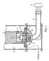
- Figure 1 is a schematic view of a flow diverter assembly located within an ultrasonic cleaning chamber in accordance with the present invention, wherein the flow diverter assembly is in a bypass position such that the filter pumps are isolated from the ultrasonic cleaning chamber, in such a bypass position any hydraulically induced flow in the cleaning chamber is bypassed to and from the fuel pool;
- Fig. 2 is a schematic view of the flow diverter assembly of Fig. 1 located in an ultrasonic cleaning chamber, wherein the flow diverter assembly is in an engaged position such that the filter pumps are aligned with the ultrasonic cleaning chamber in such an engaged position, the bypass to the pool is closed;
- Fig. 3 is an exploded schematic view of the flow diverter assembly of the present invention.
- Fig. 4 is a schematic view of the flow diverter assembly of the present invention in the engaged position, whereby the flow through the suction windows is open and the flow through the pool windows is closed;
- Fig. 5 is a schematic view of the flow diverter assembly of the present invention in the bypass position, whereby the flow through the pool windows is open and the flow through the suction windows is closed;
- Fig. 6 is a schematic view of an ultrasonic cleaning assembly with two ultrasonic cleaning chambers.
- a flow diverter assembly 10 in accordance with the present invention is illustrated in Figs. 3-5 .
- the flow diverter assembly 10 is located within an ultrasonic cleaning assembly 1.
- the flow diverter assembly 10 includes an inner movable piece 11 having a plurality of windows 111 formed thereon.
- the inner movable piece 11 is preferably formed from steel, such as 304 Stainless Steel.
- the windows 111 form a flow path.
- the movable piece 11 is supported by a spring assembly 12.
- the spring assembly 12 is capable of providing between 100-150 pounds of upward force on the movable piece 11.
- the flow diverter 10 further includes a fixed outer member 13.
- the fixed outer member 13 is preferably formed from Nitronic 60.
- the fixed outer member 13 includes a plurality of suction windows 131 and a plurality of pool windows 132.
- the suction windows 131 connect the ultrasonic cleaning chamber assembly 1 to the filter pumps (not shown), which are isolated from the cleaning chamber assembly 1.
- the pool windows 132 connect the ultrasonic cleaning chamber assembly 1 to a fuel pool (not shown).
- the movable piece 11 and the fixed outer piece 13 are made of materials specifically selected to prevent galling while the parts slide against each other.
- the flow diverter assembly 10 is located within the ultrasonic cleaning chamber assembly 1.
- the fuel assembly 3 engages the movable piece 11 of the flow diverter assembly 10.
- the fuel assembly 3 applies a downward force on the movable piece 11 such that movable piece 11 moves in a downward direction against the bias of the spring assembly 12 from a bypass position, shown in Fig. 1 , to an engaged position, shown in Fig. 2 .
- Each cleaning chamber 1 includes at least one bank of ultrasonic transducers (not shown).
- the cleaning chamber 1 and a filtration system 15 may be portable so that it can be located in the field in the spent fuel pool or in the reactor near the fuel assemblies.
- the windows 111 are aligned with the pool windows 132 on the fixed outer piece 13.
- a flow path is created between the ultrasonic cleaning chamber 1 and the fuel pool, as shown in Fig. 1 .
- the movable piece 11 includes a solid lower portion 112, which blocks a flow path to the suction windows 131. In the bypass position, there is no flow path to the suction line 14 and the filtration system 15.
- the filtration system 15 may include a pump 151 and one or more filters 152 having replaceable filter cartridges.
- FIG 6 shows an assembly with two cleaning chambers 21 and 22.
- Each chamber 21 and 22 has a suction line 14 operatively connected to the diverter assembly 10, as shown in Figs. 1 and 2 .
- the suction lines 14 are connected such that a single suction line 141 extends from the chambers 21 and 22 to the filtration assembly 15. It is contemplated that two or more cleaning chambers can be operatively connected to the suction line 141 and the single filtration system 15. In the event that the flow diverters in both cleaning chambers are in the bypass configuration (i.e., both cleaning chambers are empty (e.g., Figs.
- the suction line 141 is preferably a flexible hose, but rigid piping is considered to be well within the scope of the present invention. This maintains a safe minimum net positive suction head (NPSH) that prevents the suction pumps from cavitating.
- NPSH net positive suction head
- one or more ultrasonic cleaning chambers 1 having a diverter assembly 10 may be employed, such as a pair of cleaning chambers 21 and 22 shown in Fig. 6 .
- the chambers 21 and 22 have the same construction as the chamber 1 illustrated in Figs. 1 and 2 .
- the chambers 21 and 22 are mounted on a base plate 23 that may be located in the fuel pool when cleaning is desired.
- the flow diverter assembly 10 acts to block the suction flow from the filtration system 15, forcing suction flow through the opposite cleaning chamber 22.
- the flow diverter assembly 10 only provides suction to a cleaning chamber 21 or 22 when there is a fuel assembly 3 in the cleaning chamber, as shown in Fig. 2 .
Landscapes
- Engineering & Computer Science (AREA)
- Physics & Mathematics (AREA)
- General Engineering & Computer Science (AREA)
- High Energy & Nuclear Physics (AREA)
- Plasma & Fusion (AREA)
- Manufacturing & Machinery (AREA)
- Cleaning By Liquid Or Steam (AREA)
- Physical Or Chemical Processes And Apparatus (AREA)
- Production Of Liquid Hydrocarbon Mixture For Refining Petroleum (AREA)
- Cleaning In General (AREA)
- Pre-Mixing And Non-Premixing Gas Burner (AREA)
Abstract
Description
- The present invention relates to an improved ultrasonic cleaner assembly for irradiated nuclear fuel assemblies.
- Ultrasonic energy cleaning has been successfully employed to remove crud deposits from irradiated nuclear fuel assemblies. The initial commercial motivation for removing these deposits from pressurized water reactor (PWR) fuel has been to mitigate crud induced power shift (CIPS), also sometimes referred to as axial offset (AO) or axial offset anomaly (AOA). CIPS is a phenomenon in which deposits form on the fuel rod cladding due to the combination of local thermal hydraulic conditions and primary side fluid impurities characteristic of reactor and primary system. Certain compounds residing in these deposits act as a poison to the nuclear reaction and, because the deposits are typically thicker in the top portion of the core, cause an abnormal power distribution along the axis of the core, reducing available margin for certain types of operating conditions. As a result of CIPS, some power plants have been forced to reduce their reactor power level and hence electrical output for extended periods, which has been expensive for operation utilities.
- In addition, to mitigating CIPS, removal of crud deposits from irradiated fuel assemblies produces some other favourable results in nuclear plants of any design, including but not limited to (1) reducing the total crud inventory ("source term reduction") of plant primary systems, which leads to lower radiation dose rates for plant personnel (ALARA), (2) improving fuel inspectability, and (3) reducing potential for spread of radioactive contamination during fuel transport, storage, and reprocessing.
- Electrical generation at power plants is routinely interrupted to perform certain tasks that cannot be performed online, such as certain maintenance tasks, inspections, and reactor refuelling. During the refuelling of a main reactor, the fuel assemblies are removed from the reactor core and stored underwater near the reactor or in the plant's spent fuel pool. Later in the outage, some of the irradiated fuel assemblies are put back into the reactor core, while others are left in the spent fuel pool so that fresh assemblies can be loaded in their place. Existing ultrasonic fuel cleaning systems operate in the window when the fuel assemblies are in the spent fuel pool and available for cleaning. Because fuel offload is generally performed during critical path outage time, it has been more economical to offload fuel first, then go back and clean it after the offload is complete.
- Efforts by owners and operators of power plants to reduce outage lengths are resulting in a reduced amount of time available for cleaning fuel assemblies for those plants which perform a full core offload as part of refuelling. Furthermore, it has become standard practice in the boiling water reactor (BWR) community to keep a significant percentage of the fuel in the reactor vessel throughout the refuelling outage, in practice known as "fuel shuffling." It would be beneficial if a fuel cleaning system were capable of cleaning fuel assemblies during the movements without a significant impact on the time required to move (shuffle or offload) fuel. Such is the case with the intention presented herein.
-
EP 0,615,792 discloses an ultrasonic cleaning device for cleaning a fuel assembly. The cleaning device has an ultrasonic transducer translating mechanism which moves ultrasonic transducers vertically along a support member to enable the item to be cleaned. -
US 6, 396,892 discloses an apparatus for cleaning an irradiated nuclear fuel assembly where a housing is positioned adjacent to a nuclear fuel assembly to enable removal of deposits from the irradiated nuclear fuel assembly. - The present invention seeks to provide an improved ultrasonic cleaner.
- According to a first aspect of the present invention there is provided an improved ultrasonic cleaner assembly for irradiated nuclear fuel assemblies, comprising:
- a housing assembly for receiving a nuclear fuel assembly, wherein the housing assembly contains a fluid therein;
- a filter and pump assembly for withdrawing and filtering the fluid from the housing assembly at predetermined times; and
- a flow diverter assembly operatively connected to the housing assembly for switching a flow path between a fuel pool and a suction line to the filter and pump assembly, wherein the flow diverter assembly establishes a flow path with a fuel pool when in a by-pass position, and wherein the flow diverter assembly establishes a flow path with the suction line to the filter and pump assembly when in an engaged position,
- The present invention further extends to an improved ultrasonic cleaner assembly comprising:
- a first housing assembly for receiving a first nuclear fuel assembly, wherein the first housing assembly contains a fluid;
- a second housing assembly for receiving a second nuclear fuel assembly, wherein the second housing assembly contains the fluid;
- a filter and pump assembly for withdrawing and filtering the fluid from at least one of the first housing assembly and the second housing assembly at predetermined times;
- a first flow diverter assembly operatively connected to the first housing assembly for switching a flow path between a fuel pool when in a by-pass position and a suction line to the filter and pump assembly when in an engaged position; and
- a second flow diverter assembly operatively connected to the second housing assembly for switching a flow path between the fuel pool when in a by-pass position and the suction line to the filter and pump assembly when in an engaged position, wherein each flow diverter assembly comprises a spring biased movable member that is movable between the by-pass position and the engaged position.
- Previously, to increase fuel cleaning throughout, a power plant could install additional ultrasonic cleaning systems. Each of the cleaners would be designed such that the fuel assembly could be fully supported by the cleaner, freeing the fuel handling devices to retrieve additional fuel assemblies rather than waiting for the cleaner to finish before retrieving the next fuel assembly. Alternatively, a plant could avoid the added expense of multiple filtration systems by installing two cleaners and a single filtration system that is switched between the cleaners as necessary. Pneumatic or electronically actuated valves would control suction from the filtration system ensuring that each, cleaner received sufficient flow to flush the loosened crud from the fuel assemblies. Such a solution is less than desirable because it requires underwater actuators and active control of the valves.
- This invention provides a passive means for operating two or more cleaning chambers connected via a common header hose to a single filtration system. Each cleaning chamber has a flow diverter assembly upstream of the header hose. The flow diverter assembly is actuated by a fuel assembly when a fuel assembly is inserted into the cleaning chamber. The flow diverter acts so that each cleaning chamber is supplied with flow whenever there is a fuel assembly in the cleaning chamber. When a cleaning chamber is empty, the flow diverter acts to block the suction flow from the filtration system forcing suction flow through the opposite cleaning chamber. When both cleaning chambers are empty, suction pressure from the pump increases to the point that the flow diverters in both chambers open sufficiently to maintain flow through the pumps and prevent the pumps from cavitating.
- Embodiments of the present invention will hereinafter be described, by way of example, with reference to the accompanying drawings, in which:
-
Figure 1 is a schematic view of a flow diverter assembly located within an ultrasonic cleaning chamber in accordance with the present invention, wherein the flow diverter assembly is in a bypass position such that the filter pumps are isolated from the ultrasonic cleaning chamber, in such a bypass position any hydraulically induced flow in the cleaning chamber is bypassed to and from the fuel pool; -
Fig. 2 is a schematic view of the flow diverter assembly ofFig. 1 located in an ultrasonic cleaning chamber, wherein the flow diverter assembly is in an engaged position such that the filter pumps are aligned with the ultrasonic cleaning chamber in such an engaged position, the bypass to the pool is closed; -
Fig. 3 is an exploded schematic view of the flow diverter assembly of the present invention; -
Fig. 4 is a schematic view of the flow diverter assembly of the present invention in the engaged position, whereby the flow through the suction windows is open and the flow through the pool windows is closed; -
Fig. 5 is a schematic view of the flow diverter assembly of the present invention in the bypass position, whereby the flow through the pool windows is open and the flow through the suction windows is closed; and -
Fig. 6 is a schematic view of an ultrasonic cleaning assembly with two ultrasonic cleaning chambers. - A
flow diverter assembly 10 in accordance with the present invention is illustrated inFigs. 3-5 . Theflow diverter assembly 10 is located within anultrasonic cleaning assembly 1. Theflow diverter assembly 10 includes an innermovable piece 11 having a plurality ofwindows 111 formed thereon. The innermovable piece 11 is preferably formed from steel, such as 304 Stainless Steel. Thewindows 111 form a flow path. Themovable piece 11 is supported by aspring assembly 12. Thespring assembly 12 is capable of providing between 100-150 pounds of upward force on themovable piece 11. (It is contemplated that this force may be selected to be as high as practical while staying below the load cell trip points, typically about 10% of the weight of a fuel assembly, on the fuel handling equipment.) The flow diverter 10 further includes a fixedouter member 13. The fixedouter member 13 is preferably formed from Nitronic 60. The fixedouter member 13 includes a plurality ofsuction windows 131 and a plurality ofpool windows 132. When in an engaged position, thesuction windows 131 connect the ultrasoniccleaning chamber assembly 1 to the filter pumps (not shown), which are isolated from thecleaning chamber assembly 1. When in a bypass position, thepool windows 132 connect the ultrasoniccleaning chamber assembly 1 to a fuel pool (not shown). Themovable piece 11 and the fixedouter piece 13 are made of materials specifically selected to prevent galling while the parts slide against each other. - As illustrated in
Figs. 1 and2 , theflow diverter assembly 10 is located within the ultrasoniccleaning chamber assembly 1. As afuel assembly 3 is lowered into thecleaning chamber 1, thefuel assembly 3 engages themovable piece 11 of theflow diverter assembly 10. Thefuel assembly 3 applies a downward force on themovable piece 11 such thatmovable piece 11 moves in a downward direction against the bias of thespring assembly 12 from a bypass position, shown inFig. 1 , to an engaged position, shown inFig. 2 . Eachcleaning chamber 1 includes at least one bank of ultrasonic transducers (not shown). Thecleaning chamber 1 and afiltration system 15 may be portable so that it can be located in the field in the spent fuel pool or in the reactor near the fuel assemblies. - When the
movable piece 11 is in the bypass position, thewindows 111 are aligned with thepool windows 132 on the fixedouter piece 13. A flow path is created between theultrasonic cleaning chamber 1 and the fuel pool, as shown inFig. 1 . Themovable piece 11 includes a solidlower portion 112, which blocks a flow path to thesuction windows 131. In the bypass position, there is no flow path to thesuction line 14 and thefiltration system 15. - Once the
movable piece 11 is pushed to the engaged position by thefuel assembly 3, thewindows 111 on the movable piece are aligned with thesuction windows 132 on the fixedouter piece 13. The flow path to the pool is closed off and a new flow path to thesuction line 14 opens, as shown inFig. 2 , such that a flow path to thefiltration system 15 is opened. Thefiltration system 15 may include apump 151 and one ormore filters 152 having replaceable filter cartridges. When afuel assembly 3 is positioned within thecleaning chamber 1 such that the flow path to thefiltration system 15 is open, as shown inFig. 2 , thepump 151 withdraws water from thechamber 1 through thesuction windows 131. The water flows into thefilters 152 whereby the crud deposits are separated from the water. -
Figure 6 shows an assembly with two cleaningchambers chamber suction line 14 operatively connected to thediverter assembly 10, as shown inFigs. 1 and2 . The suction lines 14 are connected such that asingle suction line 141 extends from thechambers filtration assembly 15. It is contemplated that two or more cleaning chambers can be operatively connected to thesuction line 141 and thesingle filtration system 15. In the event that the flow diverters in both cleaning chambers are in the bypass configuration (i.e., both cleaning chambers are empty (e.g.,Figs. 1 and5 )), the pressure difference between the common suction line and the pool will become great enough to overcome the spring force of thespring assembly 12 for keeping themovable piece 11 of at least one of the cleaning chambers in the bypass position. In that case, the correspondingflow diverter 10 will move down, allowing some flow to thecommon suction line 141. Thesuction line 141 is preferably a flexible hose, but rigid piping is considered to be well within the scope of the present invention. This maintains a safe minimum net positive suction head (NPSH) that prevents the suction pumps from cavitating. - In accordance with the present invention, it is contemplated that one or more
ultrasonic cleaning chambers 1 having adiverter assembly 10 may be employed, such as a pair of cleaningchambers Fig. 6 . Thechambers chamber 1 illustrated inFigs. 1 and2 . Thechambers base plate 23 that may be located in the fuel pool when cleaning is desired. When acleaning chamber 21 is empty, theflow diverter assembly 10 acts to block the suction flow from thefiltration system 15, forcing suction flow through theopposite cleaning chamber 22. Theflow diverter assembly 10 only provides suction to acleaning chamber fuel assembly 3 in the cleaning chamber, as shown inFig. 2 . - While the invention has been described in connection with what is presently considered to be the most practical and preferred embodiments, it is to be understood that the invention is not limited to the disclosed embodiments and elements, but, to the contrary, is intended to cover various modifications. While the
diverter assembly 10 has been described in connection with an ultrasonic cleaner, it is contemplated that thediverter assembly 10 can be used in other cleaning devices. Furthermore, it is contemplated that thediverter assembly 10 may be used in other applications outside cleaning, where it is desirable to provide passive flow control. Furthermore, the dimensions of features of various components that may appear on the drawings are not meant to be limiting, and the size of the components therein can vary from the size that may be portrayed in the figures herein. - Thus, it will be appreciated that modifications to and amendments of the embodiments as described and claimed may be made within the scope of the appended claims.
Claims (20)
- An improved ultrasonic cleaner assembly (1) for irradiated nuclear fuel assemblies, comprising:a housing assembly for receiving a nuclear fuel assembly (3), wherein the housing assembly contains a fluid therein;a filter (152) and pump (151) assembly for withdrawing and filtering the fluid from the housing assembly at predetermined times; anda flow diverter assembly (10) operatively connected to the housing assembly for switching a flow path between a fuel pool and a suction line to the filter and pump assembly, wherein the flow diverter assembly establishes a flow path with a fuel pool when in a by-pass position, and wherein the flow diverter assembly establishes a flow path with the suction line to the filter and pump assembly when in an engaged position,wherein the flow diverter assembly comprises a spring biased movable member (11) that is movable between the by-pass position and the engaged position.
- An ultrasonic cleaner assembly as claimed in claim 1, wherein the flow diverter assembly (10) comprises a fixed member (13), wherein the movable member (11) is movable relative to the fixed member between the by-pass position and the engaged position.
- An ultrasonic cleaner assembly as claimed in claim 1 or claim 2, wherein the spring biased movable member (11) moves from the by-pass position to the engaged position in response to a force applied by the fuel assembly (3).
- An ultrasonic cleaner assembly (1) as claimed in claim 2 or claim 3, wherein:the fixed member (13) has at least one by-pass position window (132) formed therein and at least one engaged position window (131) formed therein;the spring biased movable member has at least one window (111) formed therein; andthe at least one window is aligned with the at least one by-pass position window when the movable member is in the by-pass position and the at least one window is aligned with the at least one engaged position window when the movable member is in the engaged position.
- An ultrasonic cleaner assembly as claimed in any preceding claim, wherein the flow diverter assembly is positioned within the housing assembly.
- An ultrasonic cleaner assembly as claimed in any preceding claim, wherein the flow path with the fuel pool is closed when the flow diverter assembly is in the engaged position.
- An ultrasonic cleaner assembly as claimed in any previous claim, wherein the flow path with the suction line to the filter and pump assembly is closed when the flow diverter assembly is in the by-pass position.
- An ultrasonic cleaner assembly as claimed in any preceding claim, wherein the flow diverter assembly permits fluid flow through the flow path with the fuel pool when in the by-pass position.
- An ultrasonic cleaner assembly as claimed in any preceding claim, wherein the movable member is spring biased towards the by-pass position.
- An improved ultrasonic cleaner assembly comprising:a first housing assembly for receiving a first nuclear fuel assembly, wherein the first housing assembly contains a fluid;a second housing assembly for receiving a second nuclear fuel assembly, wherein the second housing assembly contains the fluid;a filter and pump assembly for withdrawing and filtering the fluid from at least one of the first housing assembly and the second housing assembly at predetermined times;a first flow diverter assembly operatively connected to the first housing assembly.for switching a flow path between a fuel pool when in a by-pass position and a suction line to the filter and pump assembly when in an engaged position; anda second flow diverter assembly operatively connected to the second housing assembly for switching a flow path between the fuel pool when in a by-pass position and the suction line to the filter and pump assembly when in an engaged position, wherein each flow diverter assembly comprises a spring biased movable member that is movable between the by-pass position and the engaged position.
- An ultrasonic cleaner assembly as claimed in claim 10, wherein each flow diverter assembly comprises a fixed member, wherein the movable member is movable relative to the associated fixed member between the by-pass position and the engaged position.
- An ultrasonic cleaner assembly as claimed in claim 10 or claim 11, wherein each spring biased movable member moves from the by-pass position to the engaged position in response to a force applied by the corresponding fuel assembly.
- An ultrasonic cleaner assembly as claimed in claim 11 or claim 12, wherein:the fixed member has at least one by-pass position window formed therein and at least one engaged position window formed therein;the spring biased movable member having at least one window formed therein; andthe at least one window is aligned with the at least one by-pass position window when the movable member is in the by-pass position and the at least one window is aligned with the at least one engaged position window when the movable member is in the engaged position.
- An ultrasonic cleaner assembly as claimed in any of claims 10 to 13, wherein the first flow diverter assembly is positioned within the first housing assembly and the second flow diverter assembly is positioned within the second housing assembly.
- An ultrasonic cleaner assembly as claimed in any of claims 10 to 14, wherein both flow diverter assemblies open slightly to-allow some bypass flow when both housing assemblies are empty.
- An ultrasonic cleaner assembly as claimed in any of claims 10 to 15, wherein the first flow diverter assembly closes the flow path between the first housing assembly and the fuel pool when the first flow diverter assembly is in the engaged position.
- An ultrasonic cleaner assembly as claimed in any of claims 10 to 16, wherein the first flow diverter assembly closes the flow path between the first housing assembly and the suction line to the filter and pump assembly when the first flow diverter assembly is in the by-pass position.
- An ultrasonic cleaner assembly as claimed in any of claims 10 to 17, wherein the first flow diverter assembly permits fluid flow through the flow path with the fuel pool when in its by-pass position.
- An ultrasonic cleaner assembly as claimed in any of claims 10 to 18, wherein each movable member is spring biased towards the by-pass position.
- A flow diverter assembly comprising:a fixed outer member, wherein the fixed outer member having at least one by-pass position window formed therein and at least one engaged position window formed therein;a spring biased movable member having at least one window formed therein, wherein the movable member is movable within the fixed outer member between a by-pass position and an engaged position, wherein the movable member moves from the by-pass position to the engaged position in response to a downward force applied on the movable member by the nuclear fuel assembly, wherein the at least one window is aligned with the at least one by-pass position window when the movable member is in the by-pass position and the at least one window is aligned with the at least one engaged position window when the movable member is in the engaged position.
Applications Claiming Priority (3)
| Application Number | Priority Date | Filing Date | Title |
|---|---|---|---|
| US39872602P | 2002-07-29 | 2002-07-29 | |
| US398726P | 2002-07-29 | ||
| PCT/US2003/023485 WO2004012204A2 (en) | 2002-07-29 | 2003-07-29 | High throughput ultrasonic cleaner for irradiated nuclear fuel assemblies |
Publications (3)
| Publication Number | Publication Date |
|---|---|
| EP1527459A2 EP1527459A2 (en) | 2005-05-04 |
| EP1527459A4 EP1527459A4 (en) | 2005-11-09 |
| EP1527459B1 true EP1527459B1 (en) | 2011-04-13 |
Family
ID=31188465
Family Applications (1)
| Application Number | Title | Priority Date | Filing Date |
|---|---|---|---|
| EP03755729A Expired - Lifetime EP1527459B1 (en) | 2002-07-29 | 2003-07-29 | High throughput ultrasonic cleaner for irradiated nuclear fuel assemblies |
Country Status (11)
| Country | Link |
|---|---|
| US (1) | US7134441B2 (en) |
| EP (1) | EP1527459B1 (en) |
| JP (1) | JP4290120B2 (en) |
| KR (1) | KR100988342B1 (en) |
| CN (1) | CN1310255C (en) |
| AT (1) | ATE505793T1 (en) |
| AU (1) | AU2003273223A1 (en) |
| DE (1) | DE60336725D1 (en) |
| ES (1) | ES2360619T3 (en) |
| WO (1) | WO2004012204A2 (en) |
| ZA (1) | ZA200501687B (en) |
Families Citing this family (9)
| Publication number | Priority date | Publication date | Assignee | Title |
|---|---|---|---|---|
| US8165261B2 (en) * | 2008-01-22 | 2012-04-24 | Electric Power Research Institute, Inc. | Chemical enhancement of ultrasonic fuel cleaning |
| CN101570932B (en) | 2008-04-29 | 2012-06-27 | 海尔集团公司 | Washing machine with improved water way |
| SE534409C2 (en) * | 2009-10-01 | 2011-08-09 | Westinghouse Electric Sweden | Apparatus and method for cleaning a nuclear fuel element |
| USD808091S1 (en) * | 2016-08-19 | 2018-01-16 | Newbee New Energy Technology Co., Ltd. | Ultrasonic cleaner |
| USD825119S1 (en) * | 2016-09-28 | 2018-08-07 | Todd C. Wells | Vibrating cleaner |
| JP7101687B2 (en) * | 2017-04-20 | 2022-07-15 | ドミニオン エンジニアリング,インク. | Modular water purification system for nuclear plants |
| AU201811112S (en) * | 2018-01-31 | 2018-03-14 | Guangdong Gt Ultrasonic Co | Ultrasonic Cleaner |
| USD942096S1 (en) * | 2018-06-06 | 2022-01-25 | Lead Young Technology Co., Ltd. | Multifunctional underwear sterilizer |
| CN116748223A (en) * | 2023-06-02 | 2023-09-15 | 中国核动力研究设计院 | Hot room surface cleaning device for nuclear fuel scanning electron microscope samples after irradiation |
Family Cites Families (18)
| Publication number | Priority date | Publication date | Assignee | Title |
|---|---|---|---|---|
| JPS53100390A (en) * | 1977-02-16 | 1978-09-01 | Hitachi Ltd | Sheath pipe clad removing device |
| JPS5554500A (en) * | 1978-10-17 | 1980-04-21 | Nippon Atomic Ind Group Co | System for catching and storing decontaminated clad |
| JPS5817440B2 (en) * | 1979-09-19 | 1983-04-07 | 株式会社東芝 | Method and equipment for cleaning fuel bundles |
| JPS58188757A (en) * | 1982-04-30 | 1983-11-04 | Jidosha Kiki Co Ltd | Pressure fluid feeding device |
| GB2170578B (en) * | 1982-12-14 | 1987-01-21 | British Gas Corp | Valve |
| FR2573236B1 (en) * | 1984-11-13 | 1987-07-17 | Framatome Sa | DEVICE FOR CLEANING THE GUIDING TUBES OF THE MEASUREMENTS OF NEUTRONIC FLOWS IN A NUCLEAR PRESSURE WATER REACTOR |
| JPS62170898A (en) * | 1986-01-23 | 1987-07-27 | 東京電力株式会社 | Nuclear reactor fuel decontaminator by ultrasonic wave |
| GB2198810A (en) | 1986-12-19 | 1988-06-22 | Philips Electronic Associated | Apparatus suitable for processing semiconductor slices |
| US4828760A (en) * | 1987-03-09 | 1989-05-09 | Rockwell International Corporation | Method of cleaning a spent fuel assembly |
| IT214562Z2 (en) * | 1988-06-07 | 1990-05-09 | Itw Fastex Italia Spa | FLOW DIVERTER FOR A VEHICLE HEATING SYSTEM |
| JPH02103496A (en) * | 1988-10-12 | 1990-04-16 | Power Reactor & Nuclear Fuel Dev Corp | Dissolution method of spent nuclear fuel and the like utilizing supersonic wave |
| JPH059223U (en) * | 1991-07-29 | 1993-02-09 | ヤンマー農機株式会社 | Fertilizer application |
| JP3293928B2 (en) | 1993-02-22 | 2002-06-17 | 株式会社東芝 | Ultrasonic cleaning method and apparatus |
| US5964408A (en) | 1997-07-14 | 1999-10-12 | Musson; Cyril D. | Irrigation sprinkler and valve with flushing system |
| US5950658A (en) * | 1997-12-11 | 1999-09-14 | Hoeptner, Iii; Herbert W. | Fluid flow deverter unit |
| GB2332156B (en) | 1997-12-12 | 2002-01-23 | Sec Dep Of Science And Technol | Highly acidic mesoporous synergistic solid catalyst and its applications |
| CA2369950A1 (en) * | 1999-04-08 | 2000-10-19 | Electric Power Research Institute, Inc. | Apparatus and method for ultrasonically cleaning irradiated nuclear fuel assemblies |
| US6176596B1 (en) * | 1999-07-15 | 2001-01-23 | Thermo Power Corporation | Combination flashlight an electrical power source assembly and emitter and reflector therefor |
-
2003
- 2003-07-29 DE DE60336725T patent/DE60336725D1/en not_active Expired - Lifetime
- 2003-07-29 CN CNB038219034A patent/CN1310255C/en not_active Expired - Lifetime
- 2003-07-29 KR KR1020057001565A patent/KR100988342B1/en not_active Expired - Fee Related
- 2003-07-29 JP JP2004524916A patent/JP4290120B2/en not_active Expired - Fee Related
- 2003-07-29 US US10/628,559 patent/US7134441B2/en not_active Expired - Fee Related
- 2003-07-29 AU AU2003273223A patent/AU2003273223A1/en not_active Abandoned
- 2003-07-29 AT AT03755729T patent/ATE505793T1/en not_active IP Right Cessation
- 2003-07-29 WO PCT/US2003/023485 patent/WO2004012204A2/en not_active Ceased
- 2003-07-29 EP EP03755729A patent/EP1527459B1/en not_active Expired - Lifetime
- 2003-07-29 ES ES03755729T patent/ES2360619T3/en not_active Expired - Lifetime
-
2005
- 2005-02-25 ZA ZA200501687A patent/ZA200501687B/en unknown
Also Published As
| Publication number | Publication date |
|---|---|
| AU2003273223A1 (en) | 2004-02-16 |
| JP2005534908A (en) | 2005-11-17 |
| EP1527459A2 (en) | 2005-05-04 |
| ES2360619T3 (en) | 2011-06-07 |
| US7134441B2 (en) | 2006-11-14 |
| KR100988342B1 (en) | 2010-10-19 |
| AU2003273223A8 (en) | 2004-02-16 |
| WO2004012204A3 (en) | 2004-07-22 |
| DE60336725D1 (en) | 2011-05-26 |
| ZA200501687B (en) | 2006-05-31 |
| JP4290120B2 (en) | 2009-07-01 |
| CN1310255C (en) | 2007-04-11 |
| KR20050069974A (en) | 2005-07-05 |
| ATE505793T1 (en) | 2011-04-15 |
| EP1527459A4 (en) | 2005-11-09 |
| CN1682316A (en) | 2005-10-12 |
| US20040099294A1 (en) | 2004-05-27 |
| WO2004012204A2 (en) | 2004-02-05 |
Similar Documents
| Publication | Publication Date | Title |
|---|---|---|
| US5426681A (en) | Boiling water reactor with combined active and passive safety systems | |
| US11198630B2 (en) | Modular water purification system for nuclear power plants | |
| US7134441B2 (en) | High throughput ultrasonic cleaner for irradiated nuclear fuel assemblies | |
| WO2015191455A1 (en) | Passive filtration of air egressing from nuclear containment | |
| US5377244A (en) | Apparatus and method for chemically decontaminating a PWR reactor coolant system | |
| EP1914013B1 (en) | Method and apparatus for removing corrosion products from a nuclear reactor | |
| JPH06103360B2 (en) | Pressure relief device in nuclear reactor storage room | |
| EP2062266B1 (en) | A device for handling a fuel assembly | |
| US12548685B2 (en) | Method and apparatus for improved removal and retention of radioactive particulates from fluids | |
| WO2015156853A2 (en) | Reactor containment pressure suppression | |
| EP3714468B1 (en) | Reactor containment building spent fuel pool filter vent | |
| Hahn et al. | KALIMER preliminary conceptual design report | |
| EP3669378B1 (en) | Simplified nuclear reactor system and method of manufacturing such system | |
| Eger et al. | Commentary on spent fuel storage at Morris operation | |
| Ping et al. | AVANTech's Desludging and Water Processing Efforts in Support of the Enrico Fermi Power Plant 2 Torus Recoat Project–21224 | |
| Stručić | Possible accident scenarios related to the Spent Fuel Pool operating events | |
| Marguet | Main Circuits | |
| JP2025171534A (en) | Crud reduction device and crud reduction method | |
| Lolich | Advanced Nuclear Research Reactor | |
| Veeraraghaven | Research reactor DHRUVA | |
| Park et al. | ISLOCA Analysis for a Typical 1000MW PWR: Accident Progression, FP Distribution, and Accident Management | |
| Chao et al. | An estimation of core damage frequency of a pressurized water reactor during mid-loop operation | |
| Bulkhead et al. | DRESDEN-UFSAR | |
| JPH0342640B2 (en) | ||
| Bhawal et al. | Strategies for operation of containment related ESFs in managing activity release to the environment during accident conditions |
Legal Events
| Date | Code | Title | Description |
|---|---|---|---|
| PUAI | Public reference made under article 153(3) epc to a published international application that has entered the european phase |
Free format text: ORIGINAL CODE: 0009012 |
|
| 17P | Request for examination filed |
Effective date: 20050201 |
|
| AK | Designated contracting states |
Kind code of ref document: A2 Designated state(s): AT BE BG CH CY CZ DE DK EE ES FI FR GB GR HU IE IT LI LU MC NL PT RO SE SI SK TR |
|
| AX | Request for extension of the european patent |
Extension state: AL LT LV MK |
|
| A4 | Supplementary search report drawn up and despatched |
Effective date: 20050927 |
|
| RIC1 | Information provided on ipc code assigned before grant |
Ipc: 7G 21F 9/28 B Ipc: 7G 21C 19/42 A |
|
| DAX | Request for extension of the european patent (deleted) | ||
| GRAP | Despatch of communication of intention to grant a patent |
Free format text: ORIGINAL CODE: EPIDOSNIGR1 |
|
| GRAS | Grant fee paid |
Free format text: ORIGINAL CODE: EPIDOSNIGR3 |
|
| GRAA | (expected) grant |
Free format text: ORIGINAL CODE: 0009210 |
|
| AK | Designated contracting states |
Kind code of ref document: B1 Designated state(s): AT BE BG CH CY CZ DE DK EE ES FI FR GB GR HU IE IT LI LU MC NL PT RO SE SI SK TR |
|
| REG | Reference to a national code |
Ref country code: GB Ref legal event code: FG4D |
|
| REG | Reference to a national code |
Ref country code: CH Ref legal event code: EP |
|
| REG | Reference to a national code |
Ref country code: IE Ref legal event code: FG4D |
|
| REF | Corresponds to: |
Ref document number: 60336725 Country of ref document: DE Date of ref document: 20110526 Kind code of ref document: P |
|
| REG | Reference to a national code |
Ref country code: DE Ref legal event code: R096 Ref document number: 60336725 Country of ref document: DE Effective date: 20110526 |
|
| REG | Reference to a national code |
Ref country code: ES Ref legal event code: FG2A Ref document number: 2360619 Country of ref document: ES Kind code of ref document: T3 Effective date: 20110607 |
|
| REG | Reference to a national code |
Ref country code: NL Ref legal event code: VDEP Effective date: 20110413 |
|
| PG25 | Lapsed in a contracting state [announced via postgrant information from national office to epo] |
Ref country code: PT Free format text: LAPSE BECAUSE OF FAILURE TO SUBMIT A TRANSLATION OF THE DESCRIPTION OR TO PAY THE FEE WITHIN THE PRESCRIBED TIME-LIMIT Effective date: 20110816 Ref country code: SE Free format text: LAPSE BECAUSE OF FAILURE TO SUBMIT A TRANSLATION OF THE DESCRIPTION OR TO PAY THE FEE WITHIN THE PRESCRIBED TIME-LIMIT Effective date: 20110413 |
|
| PG25 | Lapsed in a contracting state [announced via postgrant information from national office to epo] |
Ref country code: AT Free format text: LAPSE BECAUSE OF FAILURE TO SUBMIT A TRANSLATION OF THE DESCRIPTION OR TO PAY THE FEE WITHIN THE PRESCRIBED TIME-LIMIT Effective date: 20110413 Ref country code: CY Free format text: LAPSE BECAUSE OF FAILURE TO SUBMIT A TRANSLATION OF THE DESCRIPTION OR TO PAY THE FEE WITHIN THE PRESCRIBED TIME-LIMIT Effective date: 20110413 Ref country code: FI Free format text: LAPSE BECAUSE OF FAILURE TO SUBMIT A TRANSLATION OF THE DESCRIPTION OR TO PAY THE FEE WITHIN THE PRESCRIBED TIME-LIMIT Effective date: 20110413 Ref country code: BE Free format text: LAPSE BECAUSE OF FAILURE TO SUBMIT A TRANSLATION OF THE DESCRIPTION OR TO PAY THE FEE WITHIN THE PRESCRIBED TIME-LIMIT Effective date: 20110413 Ref country code: GR Free format text: LAPSE BECAUSE OF FAILURE TO SUBMIT A TRANSLATION OF THE DESCRIPTION OR TO PAY THE FEE WITHIN THE PRESCRIBED TIME-LIMIT Effective date: 20110714 Ref country code: SI Free format text: LAPSE BECAUSE OF FAILURE TO SUBMIT A TRANSLATION OF THE DESCRIPTION OR TO PAY THE FEE WITHIN THE PRESCRIBED TIME-LIMIT Effective date: 20110413 |
|
| PG25 | Lapsed in a contracting state [announced via postgrant information from national office to epo] |
Ref country code: NL Free format text: LAPSE BECAUSE OF FAILURE TO SUBMIT A TRANSLATION OF THE DESCRIPTION OR TO PAY THE FEE WITHIN THE PRESCRIBED TIME-LIMIT Effective date: 20110413 |
|
| PG25 | Lapsed in a contracting state [announced via postgrant information from national office to epo] |
Ref country code: CZ Free format text: LAPSE BECAUSE OF FAILURE TO SUBMIT A TRANSLATION OF THE DESCRIPTION OR TO PAY THE FEE WITHIN THE PRESCRIBED TIME-LIMIT Effective date: 20110413 Ref country code: EE Free format text: LAPSE BECAUSE OF FAILURE TO SUBMIT A TRANSLATION OF THE DESCRIPTION OR TO PAY THE FEE WITHIN THE PRESCRIBED TIME-LIMIT Effective date: 20110413 |
|
| PLBE | No opposition filed within time limit |
Free format text: ORIGINAL CODE: 0009261 |
|
| STAA | Information on the status of an ep patent application or granted ep patent |
Free format text: STATUS: NO OPPOSITION FILED WITHIN TIME LIMIT |
|
| PG25 | Lapsed in a contracting state [announced via postgrant information from national office to epo] |
Ref country code: DK Free format text: LAPSE BECAUSE OF FAILURE TO SUBMIT A TRANSLATION OF THE DESCRIPTION OR TO PAY THE FEE WITHIN THE PRESCRIBED TIME-LIMIT Effective date: 20110413 Ref country code: MC Free format text: LAPSE BECAUSE OF NON-PAYMENT OF DUE FEES Effective date: 20110731 Ref country code: SK Free format text: LAPSE BECAUSE OF FAILURE TO SUBMIT A TRANSLATION OF THE DESCRIPTION OR TO PAY THE FEE WITHIN THE PRESCRIBED TIME-LIMIT Effective date: 20110413 Ref country code: RO Free format text: LAPSE BECAUSE OF FAILURE TO SUBMIT A TRANSLATION OF THE DESCRIPTION OR TO PAY THE FEE WITHIN THE PRESCRIBED TIME-LIMIT Effective date: 20110413 |
|
| REG | Reference to a national code |
Ref country code: CH Ref legal event code: PL |
|
| 26N | No opposition filed |
Effective date: 20120116 |
|
| GBPC | Gb: european patent ceased through non-payment of renewal fee |
Effective date: 20110729 |
|
| REG | Reference to a national code |
Ref country code: IE Ref legal event code: MM4A |
|
| PG25 | Lapsed in a contracting state [announced via postgrant information from national office to epo] |
Ref country code: LI Free format text: LAPSE BECAUSE OF NON-PAYMENT OF DUE FEES Effective date: 20110731 Ref country code: CH Free format text: LAPSE BECAUSE OF NON-PAYMENT OF DUE FEES Effective date: 20110731 |
|
| REG | Reference to a national code |
Ref country code: DE Ref legal event code: R097 Ref document number: 60336725 Country of ref document: DE Effective date: 20120116 |
|
| PG25 | Lapsed in a contracting state [announced via postgrant information from national office to epo] |
Ref country code: IT Free format text: LAPSE BECAUSE OF FAILURE TO SUBMIT A TRANSLATION OF THE DESCRIPTION OR TO PAY THE FEE WITHIN THE PRESCRIBED TIME-LIMIT Effective date: 20110413 |
|
| PG25 | Lapsed in a contracting state [announced via postgrant information from national office to epo] |
Ref country code: GB Free format text: LAPSE BECAUSE OF NON-PAYMENT OF DUE FEES Effective date: 20110729 |
|
| PG25 | Lapsed in a contracting state [announced via postgrant information from national office to epo] |
Ref country code: IE Free format text: LAPSE BECAUSE OF NON-PAYMENT OF DUE FEES Effective date: 20110729 |
|
| PGFP | Annual fee paid to national office [announced via postgrant information from national office to epo] |
Ref country code: DE Payment date: 20120725 Year of fee payment: 10 |
|
| PG25 | Lapsed in a contracting state [announced via postgrant information from national office to epo] |
Ref country code: LU Free format text: LAPSE BECAUSE OF NON-PAYMENT OF DUE FEES Effective date: 20110729 |
|
| PG25 | Lapsed in a contracting state [announced via postgrant information from national office to epo] |
Ref country code: BG Free format text: LAPSE BECAUSE OF FAILURE TO SUBMIT A TRANSLATION OF THE DESCRIPTION OR TO PAY THE FEE WITHIN THE PRESCRIBED TIME-LIMIT Effective date: 20110713 |
|
| PG25 | Lapsed in a contracting state [announced via postgrant information from national office to epo] |
Ref country code: TR Free format text: LAPSE BECAUSE OF FAILURE TO SUBMIT A TRANSLATION OF THE DESCRIPTION OR TO PAY THE FEE WITHIN THE PRESCRIBED TIME-LIMIT Effective date: 20110413 |
|
| PG25 | Lapsed in a contracting state [announced via postgrant information from national office to epo] |
Ref country code: HU Free format text: LAPSE BECAUSE OF FAILURE TO SUBMIT A TRANSLATION OF THE DESCRIPTION OR TO PAY THE FEE WITHIN THE PRESCRIBED TIME-LIMIT Effective date: 20110413 |
|
| REG | Reference to a national code |
Ref country code: DE Ref legal event code: R119 Ref document number: 60336725 Country of ref document: DE Effective date: 20140201 |
|
| PG25 | Lapsed in a contracting state [announced via postgrant information from national office to epo] |
Ref country code: DE Free format text: LAPSE BECAUSE OF NON-PAYMENT OF DUE FEES Effective date: 20140201 |
|
| REG | Reference to a national code |
Ref country code: FR Ref legal event code: PLFP Year of fee payment: 14 |
|
| REG | Reference to a national code |
Ref country code: FR Ref legal event code: PLFP Year of fee payment: 15 |
|
| PGFP | Annual fee paid to national office [announced via postgrant information from national office to epo] |
Ref country code: FR Payment date: 20170613 Year of fee payment: 15 |
|
| PGFP | Annual fee paid to national office [announced via postgrant information from national office to epo] |
Ref country code: ES Payment date: 20170801 Year of fee payment: 15 |
|
| PG25 | Lapsed in a contracting state [announced via postgrant information from national office to epo] |
Ref country code: FR Free format text: LAPSE BECAUSE OF NON-PAYMENT OF DUE FEES Effective date: 20180731 |
|
| REG | Reference to a national code |
Ref country code: ES Ref legal event code: FD2A Effective date: 20190917 |
|
| PG25 | Lapsed in a contracting state [announced via postgrant information from national office to epo] |
Ref country code: ES Free format text: LAPSE BECAUSE OF NON-PAYMENT OF DUE FEES Effective date: 20180730 |