EP1526935B1 - A method and device for the evacuation of casting wastes - Google Patents
A method and device for the evacuation of casting wastes Download PDFInfo
- Publication number
- EP1526935B1 EP1526935B1 EP03763793A EP03763793A EP1526935B1 EP 1526935 B1 EP1526935 B1 EP 1526935B1 EP 03763793 A EP03763793 A EP 03763793A EP 03763793 A EP03763793 A EP 03763793A EP 1526935 B1 EP1526935 B1 EP 1526935B1
- Authority
- EP
- European Patent Office
- Prior art keywords
- chest
- trolley
- casting
- chests
- ingot mould
- Prior art date
- Legal status (The legal status is an assumption and is not a legal conclusion. Google has not performed a legal analysis and makes no representation as to the accuracy of the status listed.)
- Expired - Lifetime
Links
- 238000005266 casting Methods 0.000 title claims abstract description 39
- 239000002699 waste material Substances 0.000 title claims abstract description 33
- 238000000034 method Methods 0.000 title claims abstract description 14
- 210000000038 chest Anatomy 0.000 claims abstract description 66
- 239000010814 metallic waste Substances 0.000 claims abstract description 4
- 239000011261 inert gas Substances 0.000 claims description 5
- 238000011282 treatment Methods 0.000 claims description 3
- 238000000151 deposition Methods 0.000 claims description 2
- 238000007789 sealing Methods 0.000 claims 1
- 238000009749 continuous casting Methods 0.000 description 5
- 229910000831 Steel Inorganic materials 0.000 description 4
- 239000010959 steel Substances 0.000 description 4
- QVGXLLKOCUKJST-UHFFFAOYSA-N atomic oxygen Chemical compound [O] QVGXLLKOCUKJST-UHFFFAOYSA-N 0.000 description 3
- 239000001301 oxygen Substances 0.000 description 3
- 229910052760 oxygen Inorganic materials 0.000 description 3
- 239000011819 refractory material Substances 0.000 description 3
- 238000005516 engineering process Methods 0.000 description 2
- 239000007788 liquid Substances 0.000 description 2
- 229910052751 metal Inorganic materials 0.000 description 2
- 239000002184 metal Substances 0.000 description 2
- RYGMFSIKBFXOCR-UHFFFAOYSA-N Copper Chemical compound [Cu] RYGMFSIKBFXOCR-UHFFFAOYSA-N 0.000 description 1
- 238000003723 Smelting Methods 0.000 description 1
- 239000000956 alloy Substances 0.000 description 1
- 229910045601 alloy Inorganic materials 0.000 description 1
- 239000004411 aluminium Substances 0.000 description 1
- 229910052782 aluminium Inorganic materials 0.000 description 1
- XAGFODPZIPBFFR-UHFFFAOYSA-N aluminium Chemical compound [Al] XAGFODPZIPBFFR-UHFFFAOYSA-N 0.000 description 1
- 230000000903 blocking effect Effects 0.000 description 1
- 238000004320 controlled atmosphere Methods 0.000 description 1
- 229910052802 copper Inorganic materials 0.000 description 1
- 239000010949 copper Substances 0.000 description 1
- 239000006185 dispersion Substances 0.000 description 1
- 230000008030 elimination Effects 0.000 description 1
- 238000003379 elimination reaction Methods 0.000 description 1
- 230000007613 environmental effect Effects 0.000 description 1
- 239000012467 final product Substances 0.000 description 1
- 239000007789 gas Substances 0.000 description 1
- 238000003475 lamination Methods 0.000 description 1
- 238000004519 manufacturing process Methods 0.000 description 1
- 239000000463 material Substances 0.000 description 1
- 238000005058 metal casting Methods 0.000 description 1
- 150000002739 metals Chemical class 0.000 description 1
- 238000011017 operating method Methods 0.000 description 1
- 238000003825 pressing Methods 0.000 description 1
- 239000000047 product Substances 0.000 description 1
- 230000000284 resting effect Effects 0.000 description 1
- -1 steel Chemical class 0.000 description 1
- 238000005406 washing Methods 0.000 description 1
- 238000004804 winding Methods 0.000 description 1
Images


Classifications
-
- B—PERFORMING OPERATIONS; TRANSPORTING
- B22—CASTING; POWDER METALLURGY
- B22D—CASTING OF METALS; CASTING OF OTHER SUBSTANCES BY THE SAME PROCESSES OR DEVICES
- B22D11/00—Continuous casting of metals, i.e. casting in indefinite lengths
- B22D11/14—Plants for continuous casting
- B22D11/148—Safety arrangements
-
- B—PERFORMING OPERATIONS; TRANSPORTING
- B22—CASTING; POWDER METALLURGY
- B22D—CASTING OF METALS; CASTING OF OTHER SUBSTANCES BY THE SAME PROCESSES OR DEVICES
- B22D11/00—Continuous casting of metals, i.e. casting in indefinite lengths
- B22D11/06—Continuous casting of metals, i.e. casting in indefinite lengths into moulds with travelling walls, e.g. with rolls, plates, belts, caterpillars
- B22D11/0622—Continuous casting of metals, i.e. casting in indefinite lengths into moulds with travelling walls, e.g. with rolls, plates, belts, caterpillars formed by two casting wheels
Definitions
- the present invention relates to a method and a device for the evacuation of casting wastes from a continuous metallic strip casting plant having the features of claim1.
- Metallic strips are normally produced starting from continuously cast ingots or slabs, which are reduced in thickness by a series of successive operations comprising preforging, hot and cold lamination, together with additional intermediate treatments, for example thermal ones.
- This operating method involves very expensive plant and notable expenditure of energy.
- the tendency is that of reducing the equipment and business costs by casting products with thickness as close as possible to these of the final product; consequently, following the introduction of continuous slab casting, the thickness of the latter is reduced from the conventional 200 ⁇ 300 mm to 60 ⁇ 100 mm obtained in the so-called thin slab casting (thin slab casting).
- thin slab casting thin slab casting
- a plant engineering problem is concerned with the removal of casting wastes.
- Such casting wastes are produced for example at the beginning of casting, when a strip end of insufficient quality is formed, which cannot be sent to the next phases of the process, but needs to be cut and discarded, or during emergencies in which, for example, the casting rolls forming the ingot mould are moved away from each other to drain the liquid steel contained between the casting rolls.
- the collection system generally comprises a chest coated with refractory materials, into which both the strip ends or the liquid steel loads can be allowed to fall.
- a scope of the present invention is providing a device and a method, for removing wastes below an ingot mould in a continuous casting plant, which solves the problems of the state of the art discussed above, by ensuring the presence of waste collection systems at all times during the working of the casting line, with no risk of relatively long intervals in which a collection system is not available.
- a casting plant having the features of the preamble of claim 1 is disclosed by WO 01/39914, which comprises an ingot mould, a device for the evacuation of casting wastes comprising trolley and chest suitable to contain wastes and metallic scrap without any indication of the dimensions of the trolley and the chest.
- the method also preferably comprises the removal of the trolley with the first chest full of waste for further waste treatment.
- the plant presents a much higher yield, because in a few seconds the changeover of the full chest with an empty one takes place and the first can be quickly removed from the area of the ingot mould. Furthermore, allowing the rapid closure of the inert chamber, i.e. a chamber in which an inert gas based atmosphere is maintained, during the changeover of the chest, the dispersion of gases into the outside atmosphere are very much limited, which improves the economy of the running of the plant.
- the inert chamber i.e. a chamber in which an inert gas based atmosphere is maintained
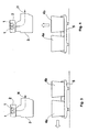
- Figures 1 and 2 show schematically a front view and a side view of an example of a preferred embodiment of a device for the evacuation of wastes according to the present invention.
- the cast strip N follows a curved path inside the inert chamber 3, constituted of a chamber in refractory materials which encloses an atmosphere of inert gas with low oxygen content in its interior.
- the feeding direction of the casting is deviated, and from vertical - upon exit from the counter-rotating rolls - becomes horizontal upon exit from the inert chamber 3.
- the inert chamber 3 is opened at its lower part, and the chest 4a is pushed against its lower edge, into which the casting wastes are made to fall from the area below the ingot mould 2.
- the waste chest 4a can be built for example as a container with the walls coated in refractory materials; the edges of the waste chest 4a and of the inert chamber 3 during the working of the continuous casting regime are kept pressing one against the other so as to form a tight closure which isolates the internal atmosphere of the inert chamber 3, low in oxygen, from the outside atmosphere.
- Appropriate washing phases of the chamber 3 with inert gas can be advantageously envisaged in the starting phases and on changing the chests.
- means 9 to introduce inert gas into the chamber 3 are envisaged, preferably close to the lower aperture. They can advantageously enter into function during the chest changeover steps.
- the waste chest 4a is transported vertically underneath the ingot mould and the initial casting axis by a trolley 5, running on rails, or in general on adequate means of motion.
- the waste chest 4a is directly raised and lowered from and towards the loading platform, or the seat of the trolley 5, with the lifting system 6, which comprises lifting arms 7 worked, for example, by a system of chains and electric motors, not shown in the figures.
- the raising and lowering route of the chests for the wastes 4a follows a vertical trajectory and the lifting arms maintain the chests in the operating position, until proceeding to the following changeover.
- other blocking systems can be envisaged, which can also exist in addition to the arms 7, to be used in the case of emergency.
- the plant is sized such that a chest 4a adjacent to the inert chamber 3 is raised completely above the obstacles at the height of the chests 4b resting on the trolley 5 and, with advancement of the trolley 4b, there are no collisions or interference between the chest 4a hitting against the inert chamber 3 and the chest 4b, when the latter is removed from the plant.
- Each trolley 5 is made so as to be provided with seats for two or more chests 4a, 4b, so that they can carry simultaneously at least two or more of them.
- the trolley can move in a direction perpendicular to the axis of the rolls of the ingot mould, even if it possible to adopt other solutions.
- FIG 2 shows a moment of the unloading phase of a waste chest 4a full of wastes, and still fixed to the inert chamber 3: the trolley 5 is positioned with its free seat 60 vertically below the chest 4a to be emptied; the arms 7, supporting the chest 4a with a downwards movement, lay it down in the free position 60 on the loading platform of the trolley 5. Successively, as shown in Figure 3, the trolley 5 runs on its wheels towards the left of the drawing, until the second chest 4b, empty, already set on the trolley 5, is positioned under the open bottom of the inert chamber 3.
- the trolley 5 is now set as in Figure 4. Successively, the mechanical arms 7 engage with appropriate parts of the empty chest 4b and raise it bringing it to abutting with the edges of the inert chamber 3 as shown in Figure 5.
- the inert chamber 3 and the new chest 4b define once again a tightly isolated environment with respect to the outside atmosphere, and can be kept filled with a controlled atmosphere, for example low in oxygen.
- the metallic strip casting process proceeds without the need for interruption.
- the trolley 5 with the chest 4a full of wastes is removed for further usage or unloaded of the wastes and the replacement of the chest 4a takes place with an empty chest.
- a trolley is immediately arranged with the loading platform empty space ready to house the chest which is being used, and an empty chest on another space of the loading platform so as to carry out the changeover immediately when the need arises.
- the trolley with the full chest can be, for example, immediately replaced by another trolley with an empty chest.
- two or more trolleys per casting machine can advantageously be envisaged, also to face the possibility that either a trolley or the chest arranged on it is inoperative, for example due to the loss of refractory.
- the trolley with a full chest can be taken immediately to an unloading place, and then immediately replaced in position beneath the casting machine.
- the time in which a chest is filled with casting wastes can be of the order of 5 - 10 min.
- the changeover operation described in general can require times of less than 3 min., for example around 1 min.
Landscapes
- Engineering & Computer Science (AREA)
- Mechanical Engineering (AREA)
- Manufacture And Refinement Of Metals (AREA)
- Casting Support Devices, Ladles, And Melt Control Thereby (AREA)
- Casting Devices For Molds (AREA)
- Mechanical Treatment Of Semiconductor (AREA)
- Mold Materials And Core Materials (AREA)
- Continuous Casting (AREA)
- Disintegrating Or Milling (AREA)
- Processing Of Solid Wastes (AREA)
Abstract
Description
- The present invention relates to a method and a device for the evacuation of casting wastes from a continuous metallic strip casting plant having the features of claim1.
- Metallic strips are normally produced starting from continuously cast ingots or slabs, which are reduced in thickness by a series of successive operations comprising preforging, hot and cold lamination, together with additional intermediate treatments, for example thermal ones. This operating method involves very expensive plant and notable expenditure of energy.
- Hence, for some time the tendency is that of reducing the equipment and business costs by casting products with thickness as close as possible to these of the final product; consequently, following the introduction of continuous slab casting, the thickness of the latter is reduced from the conventional 200÷300 mm to 60÷100 mm obtained in the so-called thin slab casting (thin slab casting). However, even the passage from 60 mm to 2-3 mm (the typical thickness of a hot strip) requires a series of energetically taxing steps.
- In view of the inherent disadvantages in casting bodies of significant thickness for reduction to thin strips, the inherent advantages in directly casting metallic strips have been recognised since the second half of the 19th century, when Sir Thomas Bessemer developed a machine for the continuous casting of steel strip consisting of cooled, counter-rotating metallic rolls set a small distance apart; the metal is cast in the space between the rolls, solidified upon contact with the cold surfaces of the latter and finally extracted with a thickness equal to the distance between the facing surfaces of the rolls themselves.
- Such extremely attractive technology has found practical uses for the casting of metals such as copper and aluminium only in the last decades of the 20th century, whilst for high smelting point metals and alloys, such as steel, at present the real industrial spread of such technology is still not manifest.
- Numerous efforts are made in this field essentially to reduce production costs, the energy consumed and the environmental impact, and to produce thin strips usable directly just like they are, in particular applications in which for example surface quality is not a particular requirement, or to be considered the same as hot laminated strips for these uses in which thickness' of les than a millimetre are necessary.
- Being established that the machine conceived by Bessemer in his time is still, in its general form, the most ideal for continuous metallic strip casting, the problems to be solved for its effective use are very numerous and range from ensuring the tightness of the rolls at their flat ends, to the most suitable materials to survive the demanding working conditions, to the automated control of all the operations and the casting speed and drawing of the strip, up to its winding into a coil.
- A plant engineering problem is concerned with the removal of casting wastes. Such casting wastes are produced for example at the beginning of casting, when a strip end of insufficient quality is formed, which cannot be sent to the next phases of the process, but needs to be cut and discarded, or during emergencies in which, for example, the casting rolls forming the ingot mould are moved away from each other to drain the liquid steel contained between the casting rolls.
- In the casting line, downstream from the casting rolls the strip is bent and made to continue horizontally on working and treating rolls. This area, substantially below the curve, and vertically below the casting rolls, is that generally destined to a collection system of metal wastes to be eliminated or reused. The collection system generally comprises a chest coated with refractory materials, into which both the strip ends or the liquid steel loads can be allowed to fall.
- With an appropriate design it is possible to realise the casting process with effectively continuous functioning, and in which the interrupting steps are very limited or completely absent. Even with such a hypothesis, the wastes must however be removed.
- In some situations, it can happen that the waste chest tends to fill up relatively quickly and, since it cannot be constructed over certain limits in size for reasons of overall dimensions, it must be emptied or changed. The chest replacement must be carried out quickly.
- A scope of the present invention is providing a device and a method, for removing wastes below an ingot mould in a continuous casting plant, which solves the problems of the state of the art discussed above, by ensuring the presence of waste collection systems at all times during the working of the casting line, with no risk of relatively long intervals in which a collection system is not available.
- A casting plant having the features of the preamble of
claim 1 is disclosed by WO 01/39914, which comprises an ingot mould, a device for the evacuation of casting wastes comprising trolley and chest suitable to contain wastes and metallic scrap without any indication of the dimensions of the trolley and the chest. - It is therefore an object of the present invention to solve the above mentioned problems by creating a continuous metallic strip casting plant, in accordance with
claim 1. According to a further aspect of the present invention said problems are solved with a metallic waste evacuation method from a continuous strip casting plant by means of the above described device, the method comprising the following steps: - a) filling a first chest of waste, fixed to an aperture in the lower part of an inert chamber located beneath the ingot mould of said casting line;
- b) positioning a first seat for chests of a trolley vertically underneath said first chest , said first seat being free, and a second housing of said trolley being occupied by a second chest;
- c) depositing said first chest with appropriate means of loading/unloading into said free housing of said trolley;
- d) moving said trolley so as to arrange said second chest underneath said aperture of the lower part of the inert chamber;
- e) gripping said second chest with said appropriate means of loading/unloading and raising it to said aperture in the lower part of the inert chamber.
- The method also preferably comprises the removal of the trolley with the first chest full of waste for further waste treatment.
- Thanks to the waste elimination method, the plant presents a much higher yield, because in a few seconds the changeover of the full chest with an empty one takes place and the first can be quickly removed from the area of the ingot mould. Furthermore, allowing the rapid closure of the inert chamber, i.e. a chamber in which an inert gas based atmosphere is maintained, during the changeover of the chest, the dispersion of gases into the outside atmosphere are very much limited, which improves the economy of the running of the plant.
- Further available advantages with the present finding are more evident, to the expert in the field, from the following detailed description of an example of a particular non-limiting embodiment with reference to the following figures, in which
- Figure 1 shows, schematically and in front view, the lifting device for a waste evacuation device for a continuous casting plant according to a preferred embodiment of the present invention;
- Figure 2 shows, schematically and in side view, a first stage of the working cycle, of unloading of a chest, of the device in Figure 1;
- Figures 3 and 4 show, schematically and in side view, two successive stages of the working cycle of the device in Figure 1;
- Figure 5 shows, schematically and in side view, a fourth stage of loading of the chest, of the working cycle of the device in Figure 1.
- Figures 1 and 2 show schematically a front view and a side view of an example of a preferred embodiment of a device for the evacuation of wastes according to the present invention.
- A pair of
counter-rotating rolls 1, contained in aningot mould 2, produce a cast in the form of a strip N, according to a procedure of continuous casting, known per se. - The cast strip N follows a curved path inside the
inert chamber 3, constituted of a chamber in refractory materials which encloses an atmosphere of inert gas with low oxygen content in its interior. The feeding direction of the casting is deviated, and from vertical - upon exit from the counter-rotating rolls - becomes horizontal upon exit from theinert chamber 3. - The
inert chamber 3 is opened at its lower part, and thechest 4a is pushed against its lower edge, into which the casting wastes are made to fall from the area below theingot mould 2. - The
waste chest 4a can be built for example as a container with the walls coated in refractory materials; the edges of thewaste chest 4a and of theinert chamber 3 during the working of the continuous casting regime are kept pressing one against the other so as to form a tight closure which isolates the internal atmosphere of theinert chamber 3, low in oxygen, from the outside atmosphere. Appropriate washing phases of thechamber 3 with inert gas can be advantageously envisaged in the starting phases and on changing the chests. Preferably, means 9 to introduce inert gas into thechamber 3 are envisaged, preferably close to the lower aperture. They can advantageously enter into function during the chest changeover steps. - The
waste chest 4a is transported vertically underneath the ingot mould and the initial casting axis by atrolley 5, running on rails, or in general on adequate means of motion. - The
waste chest 4a is directly raised and lowered from and towards the loading platform, or the seat of thetrolley 5, with the lifting system 6, which comprises liftingarms 7 worked, for example, by a system of chains and electric motors, not shown in the figures. - Advantageously, the raising and lowering route of the chests for the
wastes 4a follows a vertical trajectory and the lifting arms maintain the chests in the operating position, until proceeding to the following changeover. Alternatively other blocking systems can be envisaged, which can also exist in addition to thearms 7, to be used in the case of emergency. - Preferably, the plant is sized such that a
chest 4a adjacent to theinert chamber 3 is raised completely above the obstacles at the height of thechests 4b resting on thetrolley 5 and, with advancement of thetrolley 4b, there are no collisions or interference between thechest 4a hitting against theinert chamber 3 and thechest 4b, when the latter is removed from the plant. - Each
trolley 5 is made so as to be provided with seats for two ormore chests - Preferably the trolley can move in a direction perpendicular to the axis of the rolls of the ingot mould, even if it possible to adopt other solutions.
- We will now describe the working of the plant shown in Figures 1-5.
- Figure 2 shows a moment of the unloading phase of a
waste chest 4a full of wastes, and still fixed to the inert chamber 3: thetrolley 5 is positioned with itsfree seat 60 vertically below thechest 4a to be emptied; thearms 7, supporting thechest 4a with a downwards movement, lay it down in thefree position 60 on the loading platform of thetrolley 5. Successively, as shown in Figure 3, thetrolley 5 runs on its wheels towards the left of the drawing, until thesecond chest 4b, empty, already set on thetrolley 5, is positioned under the open bottom of theinert chamber 3. - The
trolley 5 is now set as in Figure 4. Successively, themechanical arms 7 engage with appropriate parts of theempty chest 4b and raise it bringing it to abutting with the edges of theinert chamber 3 as shown in Figure 5. - At this point the
inert chamber 3 and thenew chest 4b define once again a tightly isolated environment with respect to the outside atmosphere, and can be kept filled with a controlled atmosphere, for example low in oxygen. The metallic strip casting process proceeds without the need for interruption. Thetrolley 5 with thechest 4a full of wastes is removed for further usage or unloaded of the wastes and the replacement of thechest 4a takes place with an empty chest. - Advantageously, a trolley is immediately arranged with the loading platform empty space ready to house the chest which is being used, and an empty chest on another space of the loading platform so as to carry out the changeover immediately when the need arises.
- The trolley with the full chest can be, for example, immediately replaced by another trolley with an empty chest. With that aim, two or more trolleys per casting machine can advantageously be envisaged, also to face the possibility that either a trolley or the chest arranged on it is inoperative, for example due to the loss of refractory. Alternatively, the trolley with a full chest can be taken immediately to an unloading place, and then immediately replaced in position beneath the casting machine.
- The time in which a chest is filled with casting wastes can be of the order of 5 - 10 min. The changeover operation described in general can require times of less than 3 min., for example around 1 min.
Claims (7)
- A continuous metallic strip casting plant (N) comprising an ingot mould (1), a device for the evacuation of casting wastes comprising in its turn a trolley (5) characterised in that
the trolley (5) is supplied with at least two chests (4b) to contain wastes and metallic scrap, suitable to move and to be positioned below said ingot mould, and in that said trolley has dimensions such as to house at least two chests (4a, 4b) next to each other, and in that said chest matches the aperture of the inert chamber. - The plant according to claim 1, wherein said chests have the opening formed so as to be suitable for sealing with the aperture of a chamber (3) below the ingot mould crossed by the cast strip to define an area non communicating with the outside environment.
- The plant according to claim 2, wherein lifting means (7) are provided, said lifting means being placed below said ingot mould and suitable for raising from and for replacing on said trolley (5)at least one of said chests (4a,4b).
- The plant according to any of the previous claims, wherein said trolley (5) can house at least three chests contemporarily.
- An evacuation method of metallic waste from a continuous metallic strip casting plant according to one or more of the preceding claims, said method comprising the following steps:a) filling a first chest (4a) of waste, fixed to an aperture in the lower part of an inert chamber (3) located beneath the ingot mould of said casting line;b) positioning a first seat for chests (60) of a trolley (5) vertically underneath said first chest (4a), said first seat being free, and a second housing of said trolley being occupied by a second chest (4b);c) depositing said first chest (4a) with appropriate loading/unloading means (7) into said free housing of said trolley (5);d) moving said trolley (5) so as to arrange said second chest (4b) underneath said aperture of the lower part of the inert chamber (3);e) gripping said second chest (4b) with said appropriate loading/unloading means (7) and raising it to said aperture in the lower part of the inert chamber (3)
- The method according to claim 5 further comprising the removal of the trolley (5) with said first chest (4a) full of waste for further treatment of the wastes.
- The method according to claims 5 or 6, further comprising the step of introducing an inert gas into said inner chamber (3) during the chest changeover steps.
Applications Claiming Priority (3)
| Application Number | Priority Date | Filing Date | Title |
|---|---|---|---|
| ITMI20021511 | 2002-07-10 | ||
| IT2002MI001511A ITMI20021511A1 (en) | 2002-07-10 | 2002-07-10 | METHOD AND DEVICE FOR THE EVACUATION OF CASTING WASTE |
| PCT/EP2003/007489 WO2004007115A1 (en) | 2002-07-10 | 2003-07-10 | A method and device for the evacuation of casting wastes |
Publications (2)
| Publication Number | Publication Date |
|---|---|
| EP1526935A1 EP1526935A1 (en) | 2005-05-04 |
| EP1526935B1 true EP1526935B1 (en) | 2006-10-25 |
Family
ID=11450172
Family Applications (1)
| Application Number | Title | Priority Date | Filing Date |
|---|---|---|---|
| EP03763793A Expired - Lifetime EP1526935B1 (en) | 2002-07-10 | 2003-07-10 | A method and device for the evacuation of casting wastes |
Country Status (8)
| Country | Link |
|---|---|
| US (1) | US7140418B2 (en) |
| EP (1) | EP1526935B1 (en) |
| CN (1) | CN1302874C (en) |
| AT (1) | ATE343441T1 (en) |
| AU (1) | AU2003253054A1 (en) |
| DE (1) | DE60309330T2 (en) |
| IT (1) | ITMI20021511A1 (en) |
| WO (1) | WO2004007115A1 (en) |
Families Citing this family (1)
| Publication number | Priority date | Publication date | Assignee | Title |
|---|---|---|---|---|
| US8042869B2 (en) | 2007-07-13 | 2011-10-25 | Kids Ii, Inc. | Child seat liner |
Family Cites Families (10)
| Publication number | Priority date | Publication date | Assignee | Title |
|---|---|---|---|---|
| DE1083023B (en) * | 1954-10-20 | 1960-06-09 | Mannesmann Ag | Protective device against the effects of stopper runners or ladle breakouts during the continuous casting of iron and steel and of non-ferrous metals |
| US3344847A (en) * | 1966-03-14 | 1967-10-03 | United Eng Foundry Co | Apparatus for the continuous casting of molten metal |
| US3495651A (en) * | 1967-03-08 | 1970-02-17 | Koppers Co Inc | Starting device for continuous castings |
| FR2161821A1 (en) * | 1971-12-02 | 1973-07-13 | Fives Lille Cail | Continuous casting safety arrangement - avoids splashing molten metal after casting ladle overflows |
| AT322757B (en) * | 1972-08-17 | 1975-06-10 | Voest Ag | PROTECTIVE DEVICE FOR PREVENTING DAMAGE TO A CONTINUOUS CASTING PLANT |
| FR2207768A1 (en) * | 1972-11-24 | 1974-06-21 | Fives Lille Cail | Continuous casting ingot mould distributer - has safety appts. for high speed casting |
| US4509578A (en) * | 1982-02-12 | 1985-04-09 | General Motors Corporation | Stationary continuous automatic pouring apparatus |
| JP2893745B2 (en) * | 1989-08-17 | 1999-05-24 | 大同特殊鋼株式会社 | Continuous casting method and apparatus |
| JP3147285B2 (en) * | 1995-07-07 | 2001-03-19 | 新東工業株式会社 | Low pressure casting equipment |
| AUPQ436299A0 (en) * | 1999-12-01 | 1999-12-23 | Bhp Steel (Jla) Pty Limited | Casting steel strip |
-
2002
- 2002-07-10 IT IT2002MI001511A patent/ITMI20021511A1/en unknown
-
2003
- 2003-07-10 AT AT03763793T patent/ATE343441T1/en not_active IP Right Cessation
- 2003-07-10 AU AU2003253054A patent/AU2003253054A1/en not_active Abandoned
- 2003-07-10 US US10/520,577 patent/US7140418B2/en not_active Expired - Fee Related
- 2003-07-10 CN CNB038160536A patent/CN1302874C/en not_active Expired - Fee Related
- 2003-07-10 WO PCT/EP2003/007489 patent/WO2004007115A1/en not_active Ceased
- 2003-07-10 DE DE60309330T patent/DE60309330T2/en not_active Expired - Lifetime
- 2003-07-10 EP EP03763793A patent/EP1526935B1/en not_active Expired - Lifetime
Also Published As
| Publication number | Publication date |
|---|---|
| AU2003253054A1 (en) | 2004-02-02 |
| ATE343441T1 (en) | 2006-11-15 |
| EP1526935A1 (en) | 2005-05-04 |
| US7140418B2 (en) | 2006-11-28 |
| CN1665618A (en) | 2005-09-07 |
| DE60309330D1 (en) | 2006-12-07 |
| DE60309330T2 (en) | 2007-05-10 |
| ITMI20021511A0 (en) | 2002-07-10 |
| WO2004007115A1 (en) | 2004-01-22 |
| US20050258213A1 (en) | 2005-11-24 |
| CN1302874C (en) | 2007-03-07 |
| ITMI20021511A1 (en) | 2004-01-12 |
Similar Documents
| Publication | Publication Date | Title |
|---|---|---|
| KR101343464B1 (en) | Equipment and methods for the production of metal strips | |
| EP2694409B1 (en) | Pallet car changing device | |
| KR100353570B1 (en) | Process and device for producing a steel strip or sheet | |
| US7156150B2 (en) | Two-roll casting device | |
| KR101819881B1 (en) | Casting and Continuous Rolling Method and Plant for Making Long Metal Rolled Products | |
| US3554268A (en) | Vacuum melting furnace and method | |
| WO2006092404A1 (en) | Compact plant for continuous production of bars and/or profiles | |
| CN103878332A (en) | Magnesium alloy thick plate continuous production device and technology | |
| US7140418B2 (en) | Method and device for the evacuation of casting wastes | |
| GB1577779A (en) | Method of and apparatus for converting molten metals into solidified products | |
| US5887647A (en) | Decreasing contamination of molten metal prior to solidification casting | |
| US12280950B2 (en) | Sow casting automated guided vehicle | |
| EP3620240A1 (en) | Method for the production and the packaging of steel rods and profiles | |
| US3274653A (en) | Quickly disconnectable starter bar | |
| US10518318B2 (en) | Device and method for producing ingots | |
| CA1150079A (en) | Semi-continuous hot rolling of metal strip and plates | |
| JPH07144255A (en) | Vertical semicontinuous casting device for large cross section cast slab and carrying out method of cast slab | |
| EP1521649B1 (en) | Continuous casting plant with a deflecting device for metallic strips and deflecting method | |
| US4932462A (en) | Method and machine for the continuous casting of metal strands from high-melting metals, in particular of steel strands | |
| JP3978855B2 (en) | Optimal heating method for continuous cast slabs before hot rolling | |
| WO1999007903A1 (en) | Improvements in and relating to handling materials | |
| CN203751293U (en) | Continuous production device for magnesium alloy thick plate | |
| JPH0871736A (en) | Operation method of induction furnace for both vacuum melting and pressurized pouring | |
| WO2002042502A2 (en) | Method and equipment for handling dross and recovering the non-ferrous metals contained therein | |
| Ismail et al. | Flexible billet casting at Perwaja Steel |
Legal Events
| Date | Code | Title | Description |
|---|---|---|---|
| PUAI | Public reference made under article 153(3) epc to a published international application that has entered the european phase |
Free format text: ORIGINAL CODE: 0009012 |
|
| 17P | Request for examination filed |
Effective date: 20050208 |
|
| AK | Designated contracting states |
Kind code of ref document: A1 Designated state(s): AT BE BG CH CY CZ DE DK EE ES FI FR GB GR HU IE IT LI LU MC NL PT RO SE SI SK TR |
|
| AX | Request for extension of the european patent |
Extension state: AL LT LV MK |
|
| DAX | Request for extension of the european patent (deleted) | ||
| GRAP | Despatch of communication of intention to grant a patent |
Free format text: ORIGINAL CODE: EPIDOSNIGR1 |
|
| GRAS | Grant fee paid |
Free format text: ORIGINAL CODE: EPIDOSNIGR3 |
|
| GRAA | (expected) grant |
Free format text: ORIGINAL CODE: 0009210 |
|
| AK | Designated contracting states |
Kind code of ref document: B1 Designated state(s): AT BE BG CH CY CZ DE DK EE ES FI FR GB GR HU IE IT LI LU MC NL PT RO SE SI SK TR |
|
| PG25 | Lapsed in a contracting state [announced via postgrant information from national office to epo] |
Ref country code: RO Free format text: LAPSE BECAUSE OF FAILURE TO SUBMIT A TRANSLATION OF THE DESCRIPTION OR TO PAY THE FEE WITHIN THE PRESCRIBED TIME-LIMIT Effective date: 20061025 Ref country code: CH Free format text: LAPSE BECAUSE OF FAILURE TO SUBMIT A TRANSLATION OF THE DESCRIPTION OR TO PAY THE FEE WITHIN THE PRESCRIBED TIME-LIMIT Effective date: 20061025 Ref country code: LI Free format text: LAPSE BECAUSE OF FAILURE TO SUBMIT A TRANSLATION OF THE DESCRIPTION OR TO PAY THE FEE WITHIN THE PRESCRIBED TIME-LIMIT Effective date: 20061025 Ref country code: SI Free format text: LAPSE BECAUSE OF FAILURE TO SUBMIT A TRANSLATION OF THE DESCRIPTION OR TO PAY THE FEE WITHIN THE PRESCRIBED TIME-LIMIT Effective date: 20061025 Ref country code: NL Free format text: LAPSE BECAUSE OF FAILURE TO SUBMIT A TRANSLATION OF THE DESCRIPTION OR TO PAY THE FEE WITHIN THE PRESCRIBED TIME-LIMIT Effective date: 20061025 Ref country code: SK Free format text: LAPSE BECAUSE OF FAILURE TO SUBMIT A TRANSLATION OF THE DESCRIPTION OR TO PAY THE FEE WITHIN THE PRESCRIBED TIME-LIMIT Effective date: 20061025 Ref country code: FI Free format text: LAPSE BECAUSE OF FAILURE TO SUBMIT A TRANSLATION OF THE DESCRIPTION OR TO PAY THE FEE WITHIN THE PRESCRIBED TIME-LIMIT Effective date: 20061025 Ref country code: CZ Free format text: LAPSE BECAUSE OF FAILURE TO SUBMIT A TRANSLATION OF THE DESCRIPTION OR TO PAY THE FEE WITHIN THE PRESCRIBED TIME-LIMIT Effective date: 20061025 Ref country code: BE Free format text: LAPSE BECAUSE OF FAILURE TO SUBMIT A TRANSLATION OF THE DESCRIPTION OR TO PAY THE FEE WITHIN THE PRESCRIBED TIME-LIMIT Effective date: 20061025 |
|
| REG | Reference to a national code |
Ref country code: GB Ref legal event code: FG4D |
|
| REG | Reference to a national code |
Ref country code: CH Ref legal event code: EP |
|
| REG | Reference to a national code |
Ref country code: IE Ref legal event code: FG4D |
|
| REF | Corresponds to: |
Ref document number: 60309330 Country of ref document: DE Date of ref document: 20061207 Kind code of ref document: P |
|
| PG25 | Lapsed in a contracting state [announced via postgrant information from national office to epo] |
Ref country code: DK Free format text: LAPSE BECAUSE OF FAILURE TO SUBMIT A TRANSLATION OF THE DESCRIPTION OR TO PAY THE FEE WITHIN THE PRESCRIBED TIME-LIMIT Effective date: 20070125 Ref country code: BG Free format text: LAPSE BECAUSE OF FAILURE TO SUBMIT A TRANSLATION OF THE DESCRIPTION OR TO PAY THE FEE WITHIN THE PRESCRIBED TIME-LIMIT Effective date: 20070125 Ref country code: SE Free format text: LAPSE BECAUSE OF FAILURE TO SUBMIT A TRANSLATION OF THE DESCRIPTION OR TO PAY THE FEE WITHIN THE PRESCRIBED TIME-LIMIT Effective date: 20070125 |
|
| PG25 | Lapsed in a contracting state [announced via postgrant information from national office to epo] |
Ref country code: ES Free format text: LAPSE BECAUSE OF FAILURE TO SUBMIT A TRANSLATION OF THE DESCRIPTION OR TO PAY THE FEE WITHIN THE PRESCRIBED TIME-LIMIT Effective date: 20070205 |
|
| PG25 | Lapsed in a contracting state [announced via postgrant information from national office to epo] |
Ref country code: PT Free format text: LAPSE BECAUSE OF FAILURE TO SUBMIT A TRANSLATION OF THE DESCRIPTION OR TO PAY THE FEE WITHIN THE PRESCRIBED TIME-LIMIT Effective date: 20070326 |
|
| NLV1 | Nl: lapsed or annulled due to failure to fulfill the requirements of art. 29p and 29m of the patents act | ||
| REG | Reference to a national code |
Ref country code: CH Ref legal event code: PL |
|
| ET | Fr: translation filed | ||
| PLBE | No opposition filed within time limit |
Free format text: ORIGINAL CODE: 0009261 |
|
| STAA | Information on the status of an ep patent application or granted ep patent |
Free format text: STATUS: NO OPPOSITION FILED WITHIN TIME LIMIT |
|
| 26N | No opposition filed |
Effective date: 20070726 |
|
| GBPC | Gb: european patent ceased through non-payment of renewal fee |
Effective date: 20070710 |
|
| PG25 | Lapsed in a contracting state [announced via postgrant information from national office to epo] |
Ref country code: MC Free format text: LAPSE BECAUSE OF NON-PAYMENT OF DUE FEES Effective date: 20070731 Ref country code: GR Free format text: LAPSE BECAUSE OF FAILURE TO SUBMIT A TRANSLATION OF THE DESCRIPTION OR TO PAY THE FEE WITHIN THE PRESCRIBED TIME-LIMIT Effective date: 20070126 |
|
| PG25 | Lapsed in a contracting state [announced via postgrant information from national office to epo] |
Ref country code: GB Free format text: LAPSE BECAUSE OF NON-PAYMENT OF DUE FEES Effective date: 20070710 |
|
| PG25 | Lapsed in a contracting state [announced via postgrant information from national office to epo] |
Ref country code: IE Free format text: LAPSE BECAUSE OF NON-PAYMENT OF DUE FEES Effective date: 20070710 |
|
| PGFP | Annual fee paid to national office [announced via postgrant information from national office to epo] |
Ref country code: FR Payment date: 20080730 Year of fee payment: 6 |
|
| PG25 | Lapsed in a contracting state [announced via postgrant information from national office to epo] |
Ref country code: EE Free format text: LAPSE BECAUSE OF FAILURE TO SUBMIT A TRANSLATION OF THE DESCRIPTION OR TO PAY THE FEE WITHIN THE PRESCRIBED TIME-LIMIT Effective date: 20061025 |
|
| PG25 | Lapsed in a contracting state [announced via postgrant information from national office to epo] |
Ref country code: LU Free format text: LAPSE BECAUSE OF NON-PAYMENT OF DUE FEES Effective date: 20070710 Ref country code: CY Free format text: LAPSE BECAUSE OF FAILURE TO SUBMIT A TRANSLATION OF THE DESCRIPTION OR TO PAY THE FEE WITHIN THE PRESCRIBED TIME-LIMIT Effective date: 20061025 |
|
| PG25 | Lapsed in a contracting state [announced via postgrant information from national office to epo] |
Ref country code: TR Free format text: LAPSE BECAUSE OF FAILURE TO SUBMIT A TRANSLATION OF THE DESCRIPTION OR TO PAY THE FEE WITHIN THE PRESCRIBED TIME-LIMIT Effective date: 20061025 Ref country code: HU Free format text: LAPSE BECAUSE OF FAILURE TO SUBMIT A TRANSLATION OF THE DESCRIPTION OR TO PAY THE FEE WITHIN THE PRESCRIBED TIME-LIMIT Effective date: 20070426 |
|
| PGFP | Annual fee paid to national office [announced via postgrant information from national office to epo] |
Ref country code: AT Payment date: 20090623 Year of fee payment: 7 |
|
| REG | Reference to a national code |
Ref country code: FR Ref legal event code: ST Effective date: 20100331 |
|
| PG25 | Lapsed in a contracting state [announced via postgrant information from national office to epo] |
Ref country code: FR Free format text: LAPSE BECAUSE OF NON-PAYMENT OF DUE FEES Effective date: 20090731 |
|
| PG25 | Lapsed in a contracting state [announced via postgrant information from national office to epo] |
Ref country code: AT Free format text: LAPSE BECAUSE OF NON-PAYMENT OF DUE FEES Effective date: 20100710 |
|
| PGFP | Annual fee paid to national office [announced via postgrant information from national office to epo] |
Ref country code: DE Payment date: 20170620 Year of fee payment: 15 |
|
| PGFP | Annual fee paid to national office [announced via postgrant information from national office to epo] |
Ref country code: IT Payment date: 20180620 Year of fee payment: 16 |
|
| REG | Reference to a national code |
Ref country code: DE Ref legal event code: R119 Ref document number: 60309330 Country of ref document: DE |
|
| PG25 | Lapsed in a contracting state [announced via postgrant information from national office to epo] |
Ref country code: DE Free format text: LAPSE BECAUSE OF NON-PAYMENT OF DUE FEES Effective date: 20190201 |
|
| PG25 | Lapsed in a contracting state [announced via postgrant information from national office to epo] |
Ref country code: IT Free format text: LAPSE BECAUSE OF NON-PAYMENT OF DUE FEES Effective date: 20190710 |