EP1526739A2 - Method for extracting macro block at high speed in mobile communication system - Google Patents
Method for extracting macro block at high speed in mobile communication system Download PDFInfo
- Publication number
- EP1526739A2 EP1526739A2 EP04000061A EP04000061A EP1526739A2 EP 1526739 A2 EP1526739 A2 EP 1526739A2 EP 04000061 A EP04000061 A EP 04000061A EP 04000061 A EP04000061 A EP 04000061A EP 1526739 A2 EP1526739 A2 EP 1526739A2
- Authority
- EP
- European Patent Office
- Prior art keywords
- macro block
- motion vector
- extracted
- blocks
- extracting
- Prior art date
- Legal status (The legal status is an assumption and is not a legal conclusion. Google has not performed a legal analysis and makes no representation as to the accuracy of the status listed.)
- Withdrawn
Links
Images


Classifications
-
- H—ELECTRICITY
- H04—ELECTRIC COMMUNICATION TECHNIQUE
- H04N—PICTORIAL COMMUNICATION, e.g. TELEVISION
- H04N19/00—Methods or arrangements for coding, decoding, compressing or decompressing digital video signals
- H04N19/40—Methods or arrangements for coding, decoding, compressing or decompressing digital video signals using video transcoding, i.e. partial or full decoding of a coded input stream followed by re-encoding of the decoded output stream
-
- H—ELECTRICITY
- H04—ELECTRIC COMMUNICATION TECHNIQUE
- H04N—PICTORIAL COMMUNICATION, e.g. TELEVISION
- H04N19/00—Methods or arrangements for coding, decoding, compressing or decompressing digital video signals
- H04N19/60—Methods or arrangements for coding, decoding, compressing or decompressing digital video signals using transform coding
- H04N19/61—Methods or arrangements for coding, decoding, compressing or decompressing digital video signals using transform coding in combination with predictive coding
-
- H—ELECTRICITY
- H04—ELECTRIC COMMUNICATION TECHNIQUE
- H04N—PICTORIAL COMMUNICATION, e.g. TELEVISION
- H04N19/00—Methods or arrangements for coding, decoding, compressing or decompressing digital video signals
- H04N19/10—Methods or arrangements for coding, decoding, compressing or decompressing digital video signals using adaptive coding
- H04N19/169—Methods or arrangements for coding, decoding, compressing or decompressing digital video signals using adaptive coding characterised by the coding unit, i.e. the structural portion or semantic portion of the video signal being the object or the subject of the adaptive coding
- H04N19/17—Methods or arrangements for coding, decoding, compressing or decompressing digital video signals using adaptive coding characterised by the coding unit, i.e. the structural portion or semantic portion of the video signal being the object or the subject of the adaptive coding the unit being an image region, e.g. an object
- H04N19/176—Methods or arrangements for coding, decoding, compressing or decompressing digital video signals using adaptive coding characterised by the coding unit, i.e. the structural portion or semantic portion of the video signal being the object or the subject of the adaptive coding the unit being an image region, e.g. an object the region being a block, e.g. a macroblock
-
- H—ELECTRICITY
- H04—ELECTRIC COMMUNICATION TECHNIQUE
- H04N—PICTORIAL COMMUNICATION, e.g. TELEVISION
- H04N19/00—Methods or arrangements for coding, decoding, compressing or decompressing digital video signals
- H04N19/48—Methods or arrangements for coding, decoding, compressing or decompressing digital video signals using compressed domain processing techniques other than decoding, e.g. modification of transform coefficients, variable length coding [VLC] data or run-length data
-
- H—ELECTRICITY
- H04—ELECTRIC COMMUNICATION TECHNIQUE
- H04N—PICTORIAL COMMUNICATION, e.g. TELEVISION
- H04N19/00—Methods or arrangements for coding, decoding, compressing or decompressing digital video signals
- H04N19/50—Methods or arrangements for coding, decoding, compressing or decompressing digital video signals using predictive coding
- H04N19/503—Methods or arrangements for coding, decoding, compressing or decompressing digital video signals using predictive coding involving temporal prediction
- H04N19/51—Motion estimation or motion compensation
- H04N19/547—Motion estimation performed in a transform domain
Definitions
- the present invention relates to a method for extracting a macro block at a high speed for re-setting a motion vector when a video contents is manipulated in a discrete cosine transform (DCT) region.
- DCT discrete cosine transform
- video contents manipulation is a process for suitably manipulating previously stored video contents according to a situation of each network and a (client's) terminal before they are being provided for service to various networks.
- video contents manipulation processes include re-setting a transmission bit rate according to various band widths of diverse networks and controlling resolution of video contents according to a resolution of a display unit of the terminal.
- the former process is called a bit rate transcoding and the latter is called a resolution transcoding.
- sums of absolute difference (SAD) in the DCT region should be compared, for which a macro block predicted by a motion vector is first extracted in the DCT region.
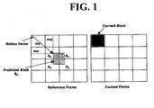
- Figure 1 illustrates a basic method for extracting a macro block in the DCT region in accordance with a conventional art, in which a horizontal component (Mx) and a vertical component (my) of the motion vector are positive numbers.
- a macro block (B 0 ) predicted by a motion vector (mv) in the DCT region overlaps with portions of four blocks (A 0 ⁇ A 3 ) of a reference frame.
- the predicted macro block (B 0 ) is motion-compensated by the portions overlapping with four blocks (A 0 ⁇ A 3 ), and the predicted block (B 0 ) is expressed by a linear combination of the blocks (A 0 ⁇ A 3 ) by using equation (1) shown below: wherein I n is a unit matrix with a size of n x n, mx and my are horizontal and vertical components of the motion vector, (mx) 8 and (my) 8 are values of modulo 8 of mx and my, respectively, and 0s expressed in P 0 ⁇ P 3 and Q 0 ⁇ Q 3 are a zero matrix having a certain dimension.
- the predicted macro block (B 0 ) is obtained by a linear combination of matrices obtained by multiplying the Pi and Qi matrices determined by mx and my to the left and right of A 0 ⁇ A 3 .
- Equation (2) is required for extracting one macro block. Accordingly, by applying equation (2) four times, one macro block consisting of four luminance component blocks can be extracted.
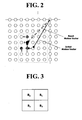
- Figure 2 shows a high speed motion vector search pattern called an HVS (Horizontal and Vertical Search) method.
- HVS Horizontal and Vertical Search
- the size of the search region of the HVS is [-2, +2], and there are four check points.
- the HVS method is that an optimum pixel position is searched in a horizontal direction in a pixel indicated by an initial motion vector, pixels positioned above and below the corresponding pixel are vertically searched to find a position of a pixel having the minimum SAD.
- a motion vector indicating the finally obtained pixel is a re-set motion vector that is finally obtained.
- a macro block indicated by the initial motion vector is extracted through equation (2) and then SAD0 is obtained.
- a motion predicted macro block indicated by a first pixel distanced as much as one pixel position leftward from the pixel indicated by the initial motion vector is obtained through equation (2), and then, SAD1 is obtained. At this time, since SAD0 > SAD1, the second pixel is checked.
- a motion predicted macro block indicated by the second pixel is extracted through equation (2), and then, SAD2 is obtained.
- SAD1 ⁇ SAD2
- a searching in a horizontal direction is finished and a position of a horizontal directional pixel indicated by a motion vector having a minimum SAD is determined as a first pixel.
- a position of the pixel indicated by the motion vector having the minimum SAD is the third pixel, and the motion vector indicating the third pixel is finally determined as the re-set motion vector.
- the macro block predicted by the motion vector is extracted in the DCT region and compared with the SAD in the DCT region, thereby re-setting the motion vector.
- equation (2) requires an excessive amount of calculation. That is, in equation (2), if mx and my are not a multiple of N, the amount of calculation is maximized, analysis of which is as follows.
- the number of multiplications required to obtain AB, a multiplication of A and B, the NxN matrix is N 3 , and the number of additions is N 2 (N-1).
- the total number of multiplications is 8N3 and total number of additions is 8N 2 (N-1). Since this amount of calculation is made for each block, in case of one macro block including four luminous components, 32N 3 times of multiplication and 32N 2 (N-1) times of addition are required.
- one object of the present invention is to provide a method for extracting a macro block at a high speed required for re-setting a motion vector.
- Another object of the present invention is to provide a method for extracting a macro block capable of reducing an excessive amount of calculation in extracting a macro block.
- a macro block extracting method in a wireless system in which a motion vector in a DCT region is reset for a video contents service between a network and a terminal, including: extracting a macro block indicated by an initial motion vector; and extracting a current macro block by using an overlap degree between the extracted macro block information and macro block information to be currently extracted.
- the extracting step includes: setting an offset motion vector value by detecting an overlap degree between the previously extracted macro block information and macro block information to be currently extracted; and obtaining luminance component blocks of the current macro block by using different equations according to the set offset motion vector value.
- the present invention proposes a fresh macro block extracting method to improve an excessive amount of calculation as in the conventional art.
- the present invention proposes a method for extracting a macro block by using such an information overlap phenomenon.
- Figure 3 illustrates positions of luminance component blocks (B 0 ⁇ B 3 ) belonging to a previously extracted macro block.
- B 0 and B 1 indicate left/upper and right/upper blocks
- B 2 and B 3 indicate left/lower and right/tower blocks.
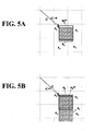
- Figures 4A, 4B, 5A and 5B show examples of overlapped previously extracted macro block information and macro block information to be currently extracted.
- B 0 (r) signifies a left/upper block of a macro block to be currently extracted.
- B 0 (r) corresponds to the left/upper block of a previously extracted macro block, and exists at a one pixel-shifted position rightward compared to the left block (B 0 ) of the previously extracted macro block.
- v 0 / n indicates an initial motion vector of the very previously extracted macro block
- v 0 / n + ⁇ indicates a motion vector of the macro block to be currently extracted.
- ⁇ indicates an offset motion vector and defined by ⁇ ⁇ (1,0),( ⁇ 1,0),(0,1),(0,-1) ⁇ .
- B 0 (r) overlaps with B 0 by as much as 8x7 pixels, and at the same time, overlaps with B 1 by as much as 8x1 pixels.
- B ( l ) / 0 signifies a left/upper block of a macro block to be currently extracted, and at a one-pixel moved position leftward compared to the left/upper block of the previously extracted macro block.
- B ( l ) / 0 overlaps with B 0 by as much as 8x7 pixels and partially overlaps with A 0 and A 2 .
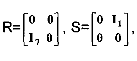
- B ( d ) / 0 at a one pixel-shifted position downward compared to B0 can be extracted by equation (6) shown below:
- B ( d ) 0 R T B 0 + S T B 2
- B and ( dir ) / 0 can be extracted by using the information overlap. That is, four luminance component blocks (B0) can be obtained depending on each type that the data information of the previously extracted macro block and the data information of the macro block to be currently extracted overlap with each other.
- each luminance component block (B 0 ⁇ B 3 ) of each current macro block differs depending on the value ⁇ , an offset motion vector.
- ⁇ is defined by ⁇ ⁇ ⁇ (1,0),(-1,0),(0,1),(0,-1) ⁇ .
- the overlap degree between the data information of the previously extracted macro block and the data information of the macro block to be currently extracted is detected, and then, the above equations are suitably used to extract luminance component blocks of the current macro block.
- Figure 6 is a flow chart of a macro block extracting method in accordance with a preferred embodiment of the present invention.
- step S11 an overlap degree between the previously extracted macro block information and the information on macro block to be currently extracted is detected, to set an offset motion vector ( ⁇ ) value (step S11).
- the offset motion vector ( ⁇ ) value is set, respective luminance component blocks (B 0 ⁇ B 3 ) in the current macro block are extracted by applying a pertinent equation according to the corresponding ( ⁇ ) value (step S12).
- the luminance component blocks (B 0 ⁇ B 3 ) of each macro block can be extracted by using suitable equations depending on the type of overlap between the previously extracted macro block information and the macro block information to be currently extracted,
- the current macro block is extracted, it is set as a previously extracted macro block (step S13). Accordingly, a motion vector indicating the currently set macro block is re-set motion vector.
- step S14 it is checked whether the motion vector re-setting has been completed. If the motion vector re-setting has been completed, every process is terminated. If, however, the motion vector re-setting has not been completed, it returns to the step S11 to repeatedly perform the process following the step S11.
- the method for extracting a macro block at a high speed of the present invention has the following advantages.
Landscapes
- Engineering & Computer Science (AREA)
- Multimedia (AREA)
- Signal Processing (AREA)
- Compression Or Coding Systems Of Tv Signals (AREA)
- Compression, Expansion, Code Conversion, And Decoders (AREA)
Abstract
Description









Claims (11)
- A macro block extracting method in a wireless system in which a motion vector in a DCT region is reset for a video contents service between a network and a terminal, comprising:extracting a macro block indicated by an initial motion vector; andextracting a current macro block by using an overlap degree between the extracted macro block information and macro block information to be currently extracted.
- The method of claim 1, wherein the extracting step comprises:setting an offset motion vector value by detecting an overlap degree between the previously extracted macro block information and macro block information to be currently extracted; andobtaining luminance component blocks of the current macro block by using different equations according to the set offset motion vector value.
- The method of claim 2, wherein the offset motion vector has a form of (1,0), (-1,0), (0,1) and (0,-1).
- The method of claim 2, wherein if the offset motion vector is (1,0), first to fourth luminance component blocks (B and (r) / 0 - B and (r) / 3) are calculated by equations shown below:
 wherein B and 0 - B and 3 indicates first to fourth luminance components of the previously extracted macro block,
 Ik is an identity matrix having a size of k x k,
 and Tk has a size of k x k, of which only the component (k-1,k-1) is 1 while the other components are all 8.
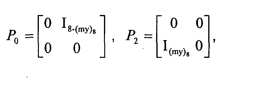
- The method of claim 4, wherein Âi(i=1,3) indicates second and fourth blocks in a reference image, and P andi(I=1,3) is such a matrix as shown below:wherein In is a unit matrix having a size of nxn, my is a vertical component of the motion vector, and (my)8 is a value of modulo 8 of my.

- The method of claim 2, wherein when the offset motion vector is (-1,0), first to fourth luminance component blocks (B and (l) / 0 - B and (l) / 3)are calculated by equation shown below:

 Uk is a matrix having a size of k x k of which only the component (0,0) is 1 while the other remaining components are all 0.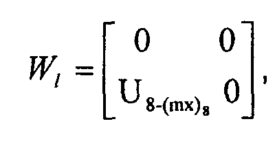
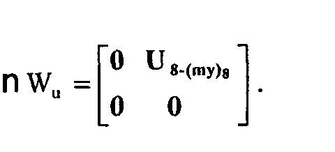
- The method of claim 5, wherein Âi(i=0,2) indicates first and third blocks, and P and i (i=0,2) is a matrix as shown below:
- The method of claim 2, wherein if the offset motion vector is (0,1), first to fourth component blocks (B and (u) / 0 - B and (u) / 0) are calculated by equations shown below:


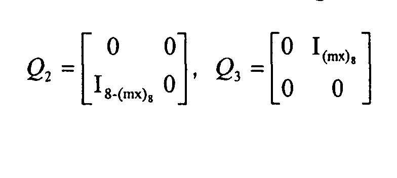
- The method of claim 8, wherein Âi (i=0,1) indicates first and second blocks in a reference image, and Q andi (i=0,1) is a matrix as shown below:wherein, mx is a horizontal motion vector, and (mx)8 is a value of modulo 8 of mx.

- The method of claim 2, wherein if the offset motion vector is (0,-1), first to fourth luminance component blocks (B and (d) / 0 - B and (d) / 3) are calculated by equations shown below:
 wherein

- The method of claim 10, wherein Âi(i=2,3) indicates third and fourth blocks in the reference image, and Q andi (i=2,3) is a matrix as shown below:
Applications Claiming Priority (2)
| Application Number | Priority Date | Filing Date | Title |
|---|---|---|---|
| KR20030071161A KR100621004B1 (en) | 2003-10-13 | 2003-10-13 | Macroblock detecting method in mobile communication system |
| KR2003071161 | 2003-10-13 |
Publications (2)
| Publication Number | Publication Date |
|---|---|
| EP1526739A2 true EP1526739A2 (en) | 2005-04-27 |
| EP1526739A3 EP1526739A3 (en) | 2006-11-02 |
Family
ID=34386773
Family Applications (1)
| Application Number | Title | Priority Date | Filing Date |
|---|---|---|---|
| EP20040000061 Withdrawn EP1526739A3 (en) | 2003-10-13 | 2004-01-05 | Method for extracting macro block at high speed in mobile communication system |
Country Status (5)
| Country | Link |
|---|---|
| US (1) | US20050078752A1 (en) |
| EP (1) | EP1526739A3 (en) |
| JP (1) | JP2005124118A (en) |
| KR (1) | KR100621004B1 (en) |
| CN (1) | CN100508617C (en) |
Families Citing this family (3)
| Publication number | Priority date | Publication date | Assignee | Title |
|---|---|---|---|---|
| WO2011049392A2 (en) * | 2009-10-21 | 2011-04-28 | 에스케이텔레콤 주식회사 | Image encoding and decoding apparatus and method |
| CN104661026B (en) | 2009-10-21 | 2018-03-27 | Sk电信有限公司 | Image coding and decoding apparatus and method |
| CN110913216A (en) * | 2013-10-12 | 2020-03-24 | 洪学文 | Image compression method combining block matching and string matching |
Family Cites Families (1)
| Publication number | Priority date | Publication date | Assignee | Title |
|---|---|---|---|---|
| US5796434A (en) * | 1996-06-07 | 1998-08-18 | Lsi Logic Corporation | System and method for performing motion estimation in the DCT domain with improved efficiency |
-
2003
- 2003-10-13 KR KR20030071161A patent/KR100621004B1/en not_active Expired - Fee Related
-
2004
- 2004-01-05 EP EP20040000061 patent/EP1526739A3/en not_active Withdrawn
- 2004-01-15 JP JP2004008554A patent/JP2005124118A/en active Pending
- 2004-02-04 CN CNB2004100036391A patent/CN100508617C/en not_active Expired - Fee Related
- 2004-06-09 US US10/863,340 patent/US20050078752A1/en not_active Abandoned
Also Published As
| Publication number | Publication date |
|---|---|
| JP2005124118A (en) | 2005-05-12 |
| US20050078752A1 (en) | 2005-04-14 |
| KR100621004B1 (en) | 2006-09-08 |
| CN100508617C (en) | 2009-07-01 |
| KR20050035480A (en) | 2005-04-18 |
| CN1607837A (en) | 2005-04-20 |
| EP1526739A3 (en) | 2006-11-02 |
Similar Documents
| Publication | Publication Date | Title |
|---|---|---|
| CN110839155B (en) | Method and device for motion estimation, electronic equipment and computer-readable storage medium | |
| EP1241893B1 (en) | Reference frame prediction and block mode prediction for fast motion searching in advanced video coding | |
| RU2461978C2 (en) | Method for scalable encoding and method for scalable decoding of video information, apparatus for said methods, program for said methods and recording medium where said program is stored | |
| JP3836559B2 (en) | Motion estimation method in digital video encoder | |
| JP4739651B2 (en) | Apparatus and method for realizing high-precision intermediate pixel high-speed search in video encoding | |
| US20090290641A1 (en) | Digital video compression acceleration based on motion vectors produced by cameras | |
| JP2001112000A (en) | Video signal encoding device | |
| JP4688462B2 (en) | Method and apparatus for differential coding of image blocks using predictive coding | |
| GB2492189A (en) | Processing colour information in an image comprising colour component sample prediction based on colour sampling format | |
| US20040264572A1 (en) | Motion prediction compensating device and its method | |
| CN112565768B (en) | Inter-frame prediction method, encoding and decoding system and computer readable storage medium | |
| JP4761390B2 (en) | Improvement of calculation method of interpolated pixel value | |
| JP3426092B2 (en) | Motion compensated inter-frame prediction method in video coding device | |
| CN110868599B (en) | Video compression method of remote desktop | |
| US8520973B2 (en) | Method for restoring transport error included in image and apparatus thereof | |
| EP1526739A2 (en) | Method for extracting macro block at high speed in mobile communication system | |
| US6912296B2 (en) | Motion estimation method | |
| EP0792488A1 (en) | Method and apparatus for regenerating a dense motion vector field | |
| KR100367468B1 (en) | Method and device for estimating motion in a digitized image with pixels | |
| CN109413445B (en) | A video transmission method and device | |
| CN117939147B (en) | Video encoding and decoding device | |
| JP4001629B2 (en) | Method and apparatus for processing pixels of an image segment by a computer | |
| KR20090065195A (en) | Fine Motion Estimation Method and Apparatus for Video Coding | |
| KR100397055B1 (en) | Motion estimator architecture for low bit rate image communication | |
| EP3754983A1 (en) | Early intra coding decision |
Legal Events
| Date | Code | Title | Description |
|---|---|---|---|
| PUAI | Public reference made under article 153(3) epc to a published international application that has entered the european phase |
Free format text: ORIGINAL CODE: 0009012 |
|
| 17P | Request for examination filed |
Effective date: 20040105 |
|
| AK | Designated contracting states |
Kind code of ref document: A2 Designated state(s): AT BE BG CH CY CZ DE DK EE ES FI FR GB GR HU IE IT LI LU MC NL PT RO SE SI SK TR |
|
| AX | Request for extension of the european patent |
Extension state: AL LT LV MK |
|
| PUAL | Search report despatched |
Free format text: ORIGINAL CODE: 0009013 |
|
| AK | Designated contracting states |
Kind code of ref document: A3 Designated state(s): AT BE BG CH CY CZ DE DK EE ES FI FR GB GR HU IE IT LI LU MC NL PT RO SE SI SK TR |
|
| AX | Request for extension of the european patent |
Extension state: AL LT LV MK |
|
| 17Q | First examination report despatched |
Effective date: 20070522 |
|
| AKX | Designation fees paid |
Designated state(s): AT BE BG CH CY CZ DE DK EE ES FI FR GB GR HU IE IT LI LU MC NL PT RO SE SI SK TR |
|
| STAA | Information on the status of an ep patent application or granted ep patent |
Free format text: STATUS: THE APPLICATION IS DEEMED TO BE WITHDRAWN |
|
| 18D | Application deemed to be withdrawn |
Effective date: 20071228 |