EP1526715A1 - Electronic camera - Google Patents
Electronic camera Download PDFInfo
- Publication number
- EP1526715A1 EP1526715A1 EP03730644A EP03730644A EP1526715A1 EP 1526715 A1 EP1526715 A1 EP 1526715A1 EP 03730644 A EP03730644 A EP 03730644A EP 03730644 A EP03730644 A EP 03730644A EP 1526715 A1 EP1526715 A1 EP 1526715A1
- Authority
- EP
- European Patent Office
- Prior art keywords
- display
- section
- image
- user
- moving image
- Prior art date
- Legal status (The legal status is an assumption and is not a legal conclusion. Google has not performed a legal analysis and makes no representation as to the accuracy of the status listed.)
- Withdrawn
Links
Images



Classifications
-
- H—ELECTRICITY
- H04—ELECTRIC COMMUNICATION TECHNIQUE
- H04N—PICTORIAL COMMUNICATION, e.g. TELEVISION
- H04N1/00—Scanning, transmission or reproduction of documents or the like, e.g. facsimile transmission; Details thereof
- H04N1/21—Intermediate information storage
- H04N1/2104—Intermediate information storage for one or a few pictures
- H04N1/2112—Intermediate information storage for one or a few pictures using still video cameras
-
- H—ELECTRICITY
- H04—ELECTRIC COMMUNICATION TECHNIQUE
- H04N—PICTORIAL COMMUNICATION, e.g. TELEVISION
- H04N23/00—Cameras or camera modules comprising electronic image sensors; Control thereof
- H04N23/60—Control of cameras or camera modules
- H04N23/63—Control of cameras or camera modules by using electronic viewfinders
-
- H—ELECTRICITY
- H04—ELECTRIC COMMUNICATION TECHNIQUE
- H04N—PICTORIAL COMMUNICATION, e.g. TELEVISION
- H04N23/00—Cameras or camera modules comprising electronic image sensors; Control thereof
- H04N23/60—Control of cameras or camera modules
- H04N23/667—Camera operation mode switching, e.g. between still and video, sport and normal or high- and low-resolution modes
Definitions
- the present invention relates to an electronic camera having a display device.
- V-signal a video synchronizing signal
- One type is a buffer used for temporarily storing data of a moving image generated by the image sensor or the like (hereinafter, referred to as a buffer for photographed image).
- the other type is a buffer used for temporarily storing data of a moving image to be displayed on the display device (hereinafter, referred to as a buffer for display image).
- a moving image displayed on the display device is always the image of an object that occurred three cycles of the V-signal earlier.
- An object of the present invention is to provide an electronic camera that can properly display a moving image usable as a viewfinder.
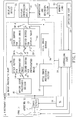
- Fig. 1 is a functional block diagram of an electronic camera according to the present invention.
- the electronic camera 1 includes a controlling section 10, a lens 11, an aperture 12, an image sensor 13, an image processing section 14, a display controlling section 15, a display device 16, a compressing/recording section 17, a TG (timing generator) 18, and an operation section 19.
- the image processing section 14 includes a moving image processing section 30, a switch SW-a, a first buffer for photographed image 31, a second buffer for photographed image 32, a switch SW-b, a switch SW-c, a first buffer for display image 33, a second buffer for display image 34, a switch SW-d, a still image processing section 35, and a still image buffer 36.
- the controlling section 10 controls the system of the electronic camera 1 as described below.
- the controlling section 10 is connected through a lens driving section (not shown) to the lens 11, and performs AF (autofocus) on the basis of the data supplied from an AF sensor (not shown) or the like.
- controlling section 10 is connected through an aperture driving section (not shown) to the aperture 12, and performs AE (auto exposure adjustment) on the basis of the data supplied from a photometry section (not shown) or the like.
- controlling section 10 is connected to each section within the image processing section 14, the display controlling section 15, the compressing/recording section 17, the TG 18, and the operation section 19, and inputs various control signals such as the V-signal output from the TG 18 to each section to control the driving timings and the like for the image processing section 14, the display controlling section 15, and the compressing/recording section 17.
- the controlling section 10 constantly monitors the states of switches constituting the operation section 19.
- the switches may include, for example, a power supply switch, a release button that can be depressed in two steps by a half-press and full-press, an AE/AF lock switch used for forcibly locking the AE and AF, and switches used for changing various modes.
- the image sensor 13 is connected to the TG 18, and is driven in accordance with various control signals output from the TG 18 to supply the image processing section 14 with image signals generated based on light incident through the lens 11 and the aperture 12.
- the moving image processing section 30 in the image processing section 14 performs various image processing for a moving image on the image signals supplied from the image sensor 13 to generate the moving image data.
- the generated moving image data is stored through the switch SW-a into the first buffer for photographed image 31 or the second buffer for photographed image 32.
- the moving image data is then stored through the switches SW-b and SW-c into the first buffer for display image 33 or the second buffer for display image 34, after which the data is supplied to the display controlling section 15 via the switch SW-d.
- the data is directly supplied to the display controlling section 15 via the switches SW-b, SW-c (position c3 thereof), and SW-d.
- the still image processing section 35 in the image processing section 14 performs various image processing for a still image on the image signals supplied from the image sensor 13 to generate the still image data.
- the generated still image data is supplied through the still image buffer 36 to the display controlling section 15 and the compressing/recording section 17.
- the display controlling section 15 converts the moving image data and still image data, both supplied as described above, to display data to be displayed on the display device 16.
- the compressing/recording section 17 compresses the still image data supplied as described above and converts it to record data to be stored into a memory card 50 (removable memory card).
- moving image capturing process in which moving image data is generated by the moving image processing section 30 by using the image signals generated by the image sensor 13, to store the generated moving image data through the switch SW-a into the first buffer for photographed image 31 or the second buffer for photographed image 32.
- a process in which the moving image data stored in the first buffer for display image 33 or the second buffer for display image 34 is supplied to the display controlling section 15 via the switch SW-d and then displayed on the display device 16 is referred to as moving image displaying process.
- a process in which the moving image data stored in the first buffer for photographed image 31 or second buffer for photographed image 32 is supplied through the switches SW-b, SW-c (position c3 thereof), and SW-d to the display controlling section 15 and then displayed on the display device 16 is also referred to as moving image displaying process.
- still image recording process a series of processes is referred to as still image recording process, in which the still image data is generated by the still image processing section 35 by using the image signals generated by the image sensor 13 and the generated still image data is supplied through the still image buffer 36 to the compressing/recording section 17 and then stored into the memory card 50.
- the still image recording process may include a process in which the still image data is supplied to the display controlling section 15 and then displayed on the display device 16.
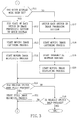
- Fig. 2 and Fig. 3 are flowcharts of the operation of the above-described electronic camera, and more particularly, showing the operation of the controlling section 10 after the power supply switch has been turned on by a user. Referring to Fig. 1, the operation of the electronic camera 1 will be described in order of the step numbers shown in Fig. 2 and Fig. 3.
- the controlling section 10 decides whether a V-signal is input or not.
- the controlling section 10 repeats the operation in step S1 until a V-signal is input, and proceeds to the operation in step S2 when the V-signal is input.
- the controlling section 10 switches the state of each switch in the image processing section 14 as follows.
- the controlling section 10 closes the switch SW-a to the position a1, switch SW-b to the b2, switch SW-c to the c2, and switch SW-d to the d1. Subsequently, when a new V-signal is input, the controlling section 10 changes the position of the switch SW-a to the position a2, switch SW-b to the b1, switch SW-c to the c1, and switch SW-d to the d2. After that, when a new V-signal is input again, the controlling section 10 changes the position of the switch SW-a to the position a1, switch SW-b to the b2, switch SW-c to the c2, and switch SW-d to the d1.
- switching the state of each switch in the image processing section 14 is to switch from/to one state (hereinafter, referred to as a first state) to/from the other state (hereinafter, referred to as a second state).
- the one state is a state in which the switch SW-a is closed to the position a1, switch SW-b to the b2, switch SW-c to the c2, and switch SW-d to the d1.
- the other state is a state in which the switch SW-a is closed to the position a2, switch SW-b to the b1, switch SW-c to the c1, and switch SW-d to the d2.
- the controlling section 10 starts the moving image capturing process.
- the controlling section 10 starts the transmittal between buffers.
- the controlling section 10 starts the moving image displaying process.
- the controlling section 10 starts performing the AE and AF.
- the controlling section 10 decides whether the release button is half-pressed or not. When the release button is half-pressed, the controlling section 10 proceeds to the operation in step S9. Otherwise, the controlling section 10 proceeds to the operation in step S8.
- the controlling section 10 decides whether the power supply switch is turned off or not. When the power supply switch is turned off, the controlling section 10 proceeds to the operation in step S22. Otherwise, the controlling section 10 returns to the operation in step S1.
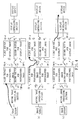
- the moving image data which has been stored in the first buffer for display image 33 in Fig. 4(b) is displayed through the display controlling section 15 on the display device 16 as shown by a thick line in Fig. 4(c).
- newly generated moving image data is stored into the first buffer for photographed image 31, and the moving image data which has been stored in the second buffer for photographed image 32 in Fig. 4(b) is transferred to the second buffer for display image 34.
- step S7 This step follows step S7 when the release button has been half-pressed in step S7.
- the controlling section 10 locks the AE and AF.
- the controlling section 10 decides whether a V-signal is input or not.
- the controlling section 10 repeats the operation in step S10 until a V-signal is input, and proceeds to the operation in step S11 in Fig. 3 when the V-signal is input.
- the controlling section 10 decides whether the user has set a mode that makes a quick display (described in detail later) valid in advance. When the mode that makes a quick display valid has been set, the controlling section 10 proceeds to the operation in step S12; otherwise, the controlling section 10 proceeds to the operation in step S17.
- the controlling section 10 fixes the state of each switch in the image processing section 14 to the state for the quick display. That is, the controlling section 10 fixes the switch SW-a to the position a1, switch SW-b to the b1, switch SW-c to the c3, and switch SW-d to the d3.
- the controlling section 10 starts the moving image capturing process.
- the controlling section 10 starts the moving image displaying process.
- the moving image data stored in the first buffer for photographed image 31 is directly supplied to the display controlling section 15 without passing through the first buffer for display image 33 as shown by a thick line in Fig. 5.
- Moving image data newly stored in the first buffer for photographed image 31 in the moving image capturing process can thus be displayed on the display device more quickly than the normal display.
- this type of display is referred to as quick display.
- the controlling section 10 decides whether the release button is full-pressed or not. When the release button is full-pressed, the controlling section 10 proceeds to the operation in step S21; otherwise, the controlling section 10 proceeds to the operation in step S16.
- the controlling section 10 decides whether the release button is half-pressed or not. When the release button is half-pressed, the controlling section 10 returns to the operation in step S10; otherwise (that is, when the press of the release button is released), the controlling section 10 returns to the operation in step S1.
- steps S10 to S16 are repeated to carry out continuous quick display as long as the release button is half-pressed.
- This step follows step S11 if the quick display mode is disabled.
- the controlling section 10 changes the state of each switch in the image processing section 14 as in step S2.
- the controlling section 10 starts the moving image capturing process as in step S3.
- the controlling section 10 starts the transmittal between buffers as in step S4.
- the controlling section 10 starts the moving image displaying process as in step S5 and then proceeds to the operation in step S15. Accordingly, when the quick display mode is disabled, the operations in steps S10, S11, S17 to S20, S15, and S16 are repeated to carry out the continuous normal display as long as the release button is half-pressed.
- step S15 if the release button has been full-pressed in step S15.
- the controlling section 10 starts the still image recording process and then returns to the operation in step S1. Accordingly, the operations after step 1 are repeated when the release button is full-pressed to perform the still image recording process or when the press of the release button is released as described above.
- step S8 if the power supply switch has been turned off in step S8.
- the controlling section 10 performs a predetermined power off process and the operation of the controlling section 10 terminates.
- the user can choose the normal display (steps S3 to S5), placing importance on a synchronization.
- the user can choose the quick display (steps S12 to S14), placing importance on a response feature.
- the normal display and the quick display can thus be switched from each other appropriately depending on the features. Therefore, according to the embodiment, the user can release the shutter at the right moment.
- this switching may also be performed when the AE/AF lock switch is turned on.
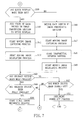
- the controlling section 10 repeats the operations in steps S30 to S36 in Fig. 6 to perform the normal display until the AE/AF lock switch is turned on. When the AE/AF lock switch is turned on, then the controlling section 10 locks the AE/AF function (step S37 in Fig. 6).
- step S39 When the mode in which quick display is enabled is set in step S39, the operations in steps S38 in Fig. 6 to S45 in Fig. 7 are repeated to perform the quick display until the release button is full-pressed.
- step S39 When the mode in which quick display is not enabled is set in step S39, on the other hand, the controlling section 10 repeats the operations in step S38 in Fig. 6 and in steps S39, S46 to S49, and S43 to S45 in Fig. 7 to perform the normal display.
- the controlling section 10 When the release button is full-pressed while the quick or normal display is performed after the AE/AF lock switch has been turned on, the controlling section 10 performs the still image recording process (step S50 in Fig. 7); when the power supply switch is turned off, the controlling section 10 performs a power off process (step S51 in Fig. 7).
- a buffer section described in the claims corresponds to the first and second buffers for display image 33 and 34.
- a recording section described in the claims corresponds to the compressing/recording section 17.
- a display switching section described in the claims corresponds to a function of the controlling section 10 that switches the states of the switches SW-a, SW-b, SW-c, and SW-d.
- a first display described in the claims corresponds to the normal display.
- a second display described in the claims corresponds to the quick display.
- predetermined timing corresponds to a timing immediately after the release button is half-pressed (when the mode in which quick display is enabled).
- a shooting condition adjusting section described in Claim 2 corresponds to a function of the controlling section 10 that performs the AE and AF in step S6.
- the electronic camera of the invention can properly display a moving image that is usable as a viewfinder.
Landscapes
- Engineering & Computer Science (AREA)
- Multimedia (AREA)
- Signal Processing (AREA)
- Studio Devices (AREA)
Abstract
Description
Claims (6)
- An electronic camera comprising:an image pickup section photographing an object to generate an image;a display device displaying the image generated by the image pickup section as a moving image;a buffer section temporarily storing therein the image generated by the image pickup section and to be displayed as a moving image on the display device; anda recording section recording thereon the image generated by the image pickup section according to a user's operation, whereinthe electronic camera further comprises a display switching section which switches a first display and a second display at a predetermined timing, the first display being for performing display of a moving image on the display device through the buffer section, the second display being for performing display of a moving image not through the buffer section.
- The electronic camera according to Claim 1, comprising:an operating member receiving a user's operation when pressed in two steps, the user's operation being associated with the image recording by the recording section; anda shooting condition adjusting section performing at least one of auto exposure adjustment and autofocus until the operating member is pressed in a first step, whereinthe display switching section performs the first display until the operating member is pressed in the first step, and switches the first display to the second display when the release button is pressed in the first step.
- The electronic camera according to Claim 1, comprising:an exposure adjusting section performing auto exposure adjustment; andan operating member receiving a user's operation to stop the auto exposure adjustment, whereinthe display switching section performs the first display until the user's operation to stop the auto exposure adjustment is received by the operating member, and switches the first display to the second display when the user's operation to stop the auto exposure adjustment is received.
- The electronic camera according to Claim 1, comprising:a focusing section performing autofocus; andan operating member receiving a user's operation to stop the autofocus, whereinthe display switching section performs the first display until the user's operation to stop the autofocus is received by the operating member, and switches the first display to the second display when the user's operation to stop the autofocus is received.
- The electronic camera according to Claim 1, comprising:an exposure adjusting section performing auto exposure adjustment;a focusing section performing autofocus; andan operating member receiving a user's operation to stop the auto exposure adjustment and autofocus, whereinthe display switching section performs the first display until the user's operation to stop the auto exposure adjustment and autofocus is received by the operating member, and switches the first display to the second display when the user's operation to stop the auto exposure adjustment and autofocus is received.
- The electronic camera according to Claim 1, wherein:the display switching section decides whether or not to enable implementation of the second display according to a user's operation.
Priority Applications (1)
| Application Number | Priority Date | Filing Date | Title |
|---|---|---|---|
| EP17001113.4A EP3244605A1 (en) | 2002-05-28 | 2003-05-27 | Electronic camera |
Applications Claiming Priority (3)
| Application Number | Priority Date | Filing Date | Title |
|---|---|---|---|
| JP2002154004A JP3757905B2 (en) | 2002-05-28 | 2002-05-28 | Electronic camera |
| JP2002154004 | 2002-05-28 | ||
| PCT/JP2003/006602 WO2003101090A1 (en) | 2002-05-28 | 2003-05-27 | Electronic camera |
Related Child Applications (1)
| Application Number | Title | Priority Date | Filing Date |
|---|---|---|---|
| EP17001113.4A Division EP3244605A1 (en) | 2002-05-28 | 2003-05-27 | Electronic camera |
Publications (2)
| Publication Number | Publication Date |
|---|---|
| EP1526715A1 true EP1526715A1 (en) | 2005-04-27 |
| EP1526715A4 EP1526715A4 (en) | 2006-08-02 |
Family
ID=29561338
Family Applications (2)
| Application Number | Title | Priority Date | Filing Date |
|---|---|---|---|
| EP03730644A Withdrawn EP1526715A4 (en) | 2002-05-28 | 2003-05-27 | ELECTRONIC CAMERA |
| EP17001113.4A Withdrawn EP3244605A1 (en) | 2002-05-28 | 2003-05-27 | Electronic camera |
Family Applications After (1)
| Application Number | Title | Priority Date | Filing Date |
|---|---|---|---|
| EP17001113.4A Withdrawn EP3244605A1 (en) | 2002-05-28 | 2003-05-27 | Electronic camera |
Country Status (5)
| Country | Link |
|---|---|
| US (1) | US7443423B2 (en) |
| EP (2) | EP1526715A4 (en) |
| JP (1) | JP3757905B2 (en) |
| CN (1) | CN1656794A (en) |
| WO (1) | WO2003101090A1 (en) |
Families Citing this family (5)
| Publication number | Priority date | Publication date | Assignee | Title |
|---|---|---|---|---|
| JP5058607B2 (en) * | 2006-02-08 | 2012-10-24 | キヤノン株式会社 | Imaging device, control method thereof, and program |
| JP5056370B2 (en) * | 2007-11-22 | 2012-10-24 | ソニー株式会社 | IMAGING DEVICE, IMAGING DEVICE CONTROL METHOD, IMAGING DEVICE CONTROL PROGRAM, DATA PROCESSING DEVICE, DATA PROCESSING METHOD, AND DATA PROCESSING PROGRAM |
| JP4751939B2 (en) * | 2009-03-31 | 2011-08-17 | アイシン精機株式会社 | Car camera calibration system |
| US9154700B2 (en) | 2009-10-16 | 2015-10-06 | Samsung Electronics Co., Ltd. | Apparatus and method for image capture using image stored in camera |
| JP5783737B2 (en) * | 2011-02-02 | 2015-09-24 | キヤノン株式会社 | Image pickup apparatus and moving image recording apparatus control method |
Family Cites Families (9)
| Publication number | Priority date | Publication date | Assignee | Title |
|---|---|---|---|---|
| US6359649B1 (en) * | 1995-04-04 | 2002-03-19 | Canon Kabushiki Kaisa | Video camera integrated with still camera |
| JPH10224684A (en) * | 1997-02-10 | 1998-08-21 | Nikon Corp | Information processing device |
| US6020920A (en) * | 1997-06-10 | 2000-02-01 | Flashpoint Technology, Inc. | Method and system for speculative decompression of compressed image data in an image capture unit |
| US6137534A (en) * | 1997-07-10 | 2000-10-24 | Flashpoint Technology, Inc. | Method and apparatus for providing live view and instant review in an image capture device |
| US6563535B1 (en) * | 1998-05-19 | 2003-05-13 | Flashpoint Technology, Inc. | Image processing system for high performance digital imaging devices |
| JPH11355624A (en) * | 1998-06-05 | 1999-12-24 | Fuji Photo Film Co Ltd | Imaging equipment |
| US7012641B2 (en) * | 2000-02-14 | 2006-03-14 | Canon Kabushiki Kaisha | Image sensing apparatus, method, memory involving differential compression of display region based on zoom operation or speed |
| US7064784B2 (en) * | 2000-10-19 | 2006-06-20 | Canon Kabushiki Kaisha | Image pickup apparatus adapted to carry out parallel operations in a continuous image pickup mode, and a control method |
| JP2003209731A (en) * | 2002-01-09 | 2003-07-25 | Sony Corp | Image signal processing method and imaging device |
-
2002
- 2002-05-28 JP JP2002154004A patent/JP3757905B2/en not_active Expired - Fee Related
-
2003
- 2003-05-27 US US10/515,224 patent/US7443423B2/en not_active Expired - Fee Related
- 2003-05-27 WO PCT/JP2003/006602 patent/WO2003101090A1/en not_active Ceased
- 2003-05-27 CN CNA038120984A patent/CN1656794A/en active Pending
- 2003-05-27 EP EP03730644A patent/EP1526715A4/en not_active Withdrawn
- 2003-05-27 EP EP17001113.4A patent/EP3244605A1/en not_active Withdrawn
Also Published As
| Publication number | Publication date |
|---|---|
| JP2003348427A (en) | 2003-12-05 |
| CN1656794A (en) | 2005-08-17 |
| JP3757905B2 (en) | 2006-03-22 |
| US7443423B2 (en) | 2008-10-28 |
| WO2003101090A1 (en) | 2003-12-04 |
| EP3244605A1 (en) | 2017-11-15 |
| EP1526715A4 (en) | 2006-08-02 |
| US20050151870A1 (en) | 2005-07-14 |
Similar Documents
| Publication | Publication Date | Title |
|---|---|---|
| US7710468B2 (en) | Imaging apparatus with memory for storing camera through image data | |
| KR101086409B1 (en) | Digital image processing device control method for photographing user set continuous shutter mode and device therefor | |
| KR101692398B1 (en) | Digital photographing apparatus and control method thereof | |
| JP4865648B2 (en) | Imaging device | |
| US20110199498A1 (en) | Image pickup apparatus | |
| US7443423B2 (en) | Electronic camera | |
| EP2080366B1 (en) | Image capture in auto-focus digital cameras | |
| EP1526718A1 (en) | Electronic camera | |
| JP2003259201A (en) | Digital camera and exposure control device | |
| US7616236B2 (en) | Control method used by digital image processing apparatus | |
| JP2025164307A (en) | Imaging system, control method and program thereof | |
| JP2002281375A (en) | Electronic camera and image display method in the case of automatic focus adjustment | |
| JP4331087B2 (en) | Imaging apparatus and control method thereof | |
| JP2012063722A (en) | Image pickup apparatus and display control method | |
| JP2005045511A (en) | Stereoscopic photographing device and its control method | |
| JP2005039401A (en) | Camera and photographing method of stereoscopic image | |
| JP2000231055A (en) | Auto focus camera | |
| JP2010107900A (en) | Imaging apparatus, compound eye imaging apparatus, imaging method and program | |
| JPH118795A (en) | Electronic imaging device | |
| JPH1070696A (en) | Electronic still camera | |
| JP2001197359A (en) | Synchronism control method and image pickup device | |
| JP2007124194A (en) | Electronic camera | |
| JP2001290186A (en) | Imaging apparatus, control method of imaging apparatus, and computer program applicable to imaging apparatus | |
| JPH1070697A (en) | Electronic still camera | |
| JP2001169226A (en) | Electronic camera with electronic viewfinder |
Legal Events
| Date | Code | Title | Description |
|---|---|---|---|
| PUAI | Public reference made under article 153(3) epc to a published international application that has entered the european phase |
Free format text: ORIGINAL CODE: 0009012 |
|
| 17P | Request for examination filed |
Effective date: 20041222 |
|
| AK | Designated contracting states |
Kind code of ref document: A1 Designated state(s): AT BE BG CH CY CZ DE DK EE ES FI FR GB GR HU IE IT LI LU MC NL PT RO SE SI SK TR |
|
| RBV | Designated contracting states (corrected) |
Designated state(s): DE FR GB |
|
| A4 | Supplementary search report drawn up and despatched |
Effective date: 20060629 |
|
| 17Q | First examination report despatched |
Effective date: 20061121 |
|
| RAP1 | Party data changed (applicant data changed or rights of an application transferred) |
Owner name: NIKON CORPORATION |
|
| RAP1 | Party data changed (applicant data changed or rights of an application transferred) |
Owner name: NIKON CORPORATION |
|
| STAA | Information on the status of an ep patent application or granted ep patent |
Free format text: STATUS: EXAMINATION IS IN PROGRESS |
|
| STAA | Information on the status of an ep patent application or granted ep patent |
Free format text: STATUS: THE APPLICATION IS DEEMED TO BE WITHDRAWN |
|
| 18D | Application deemed to be withdrawn |
Effective date: 20170714 |