EP1526542A2 - Information recording apparatus, information recording method and information recording program - Google Patents
Information recording apparatus, information recording method and information recording program Download PDFInfo
- Publication number
- EP1526542A2 EP1526542A2 EP04256431A EP04256431A EP1526542A2 EP 1526542 A2 EP1526542 A2 EP 1526542A2 EP 04256431 A EP04256431 A EP 04256431A EP 04256431 A EP04256431 A EP 04256431A EP 1526542 A2 EP1526542 A2 EP 1526542A2
- Authority
- EP
- European Patent Office
- Prior art keywords
- recording
- data
- reference position
- shift quantity
- sync pattern
- Prior art date
- Legal status (The legal status is an assumption and is not a legal conclusion. Google has not performed a legal analysis and makes no representation as to the accuracy of the status listed.)
- Withdrawn
Links
- 238000000034 method Methods 0.000 title claims description 71
- 230000003287 optical effect Effects 0.000 abstract description 72
- 238000010586 diagram Methods 0.000 description 11
- 230000001360 synchronised effect Effects 0.000 description 4
- 238000006243 chemical reaction Methods 0.000 description 2
- 230000007423 decrease Effects 0.000 description 2
- 230000003247 decreasing effect Effects 0.000 description 2
- 230000008646 thermal stress Effects 0.000 description 2
- 230000005540 biological transmission Effects 0.000 description 1
- 238000004590 computer program Methods 0.000 description 1
- 238000012937 correction Methods 0.000 description 1
- 230000000694 effects Effects 0.000 description 1
- 238000007429 general method Methods 0.000 description 1
- 238000004519 manufacturing process Methods 0.000 description 1
- 238000012545 processing Methods 0.000 description 1
Images


Classifications
-
- G—PHYSICS
- G11—INFORMATION STORAGE
- G11B—INFORMATION STORAGE BASED ON RELATIVE MOVEMENT BETWEEN RECORD CARRIER AND TRANSDUCER
- G11B27/00—Editing; Indexing; Addressing; Timing or synchronising; Monitoring; Measuring tape travel
- G11B27/10—Indexing; Addressing; Timing or synchronising; Measuring tape travel
- G11B27/19—Indexing; Addressing; Timing or synchronising; Measuring tape travel by using information detectable on the record carrier
- G11B27/28—Indexing; Addressing; Timing or synchronising; Measuring tape travel by using information detectable on the record carrier by using information signals recorded by the same method as the main recording
- G11B27/30—Indexing; Addressing; Timing or synchronising; Measuring tape travel by using information detectable on the record carrier by using information signals recorded by the same method as the main recording on the same track as the main recording
- G11B27/3027—Indexing; Addressing; Timing or synchronising; Measuring tape travel by using information detectable on the record carrier by using information signals recorded by the same method as the main recording on the same track as the main recording used signal is digitally coded
-
- G—PHYSICS
- G11—INFORMATION STORAGE
- G11B—INFORMATION STORAGE BASED ON RELATIVE MOVEMENT BETWEEN RECORD CARRIER AND TRANSDUCER
- G11B20/00—Signal processing not specific to the method of recording or reproducing; Circuits therefor
- G11B20/10—Digital recording or reproducing
- G11B20/12—Formatting, e.g. arrangement of data block or words on the record carriers
- G11B20/1217—Formatting, e.g. arrangement of data block or words on the record carriers on discs
-
- G—PHYSICS
- G11—INFORMATION STORAGE
- G11B—INFORMATION STORAGE BASED ON RELATIVE MOVEMENT BETWEEN RECORD CARRIER AND TRANSDUCER
- G11B20/00—Signal processing not specific to the method of recording or reproducing; Circuits therefor
- G11B20/10—Digital recording or reproducing
- G11B20/12—Formatting, e.g. arrangement of data block or words on the record carriers
- G11B2020/1264—Formatting, e.g. arrangement of data block or words on the record carriers wherein the formatting concerns a specific kind of data
- G11B2020/1265—Control data, system data or management information, i.e. data used to access or process user data
- G11B2020/1287—Synchronisation pattern, e.g. VCO fields
-
- G—PHYSICS
- G11—INFORMATION STORAGE
- G11B—INFORMATION STORAGE BASED ON RELATIVE MOVEMENT BETWEEN RECORD CARRIER AND TRANSDUCER
- G11B2220/00—Record carriers by type
- G11B2220/20—Disc-shaped record carriers
- G11B2220/21—Disc-shaped record carriers characterised in that the disc is of read-only, rewritable, or recordable type
- G11B2220/215—Recordable discs
- G11B2220/216—Rewritable discs
-
- G—PHYSICS
- G11—INFORMATION STORAGE
- G11B—INFORMATION STORAGE BASED ON RELATIVE MOVEMENT BETWEEN RECORD CARRIER AND TRANSDUCER
- G11B2220/00—Record carriers by type
- G11B2220/20—Disc-shaped record carriers
- G11B2220/25—Disc-shaped record carriers characterised in that the disc is based on a specific recording technology
- G11B2220/2537—Optical discs
-
- G—PHYSICS
- G11—INFORMATION STORAGE
- G11B—INFORMATION STORAGE BASED ON RELATIVE MOVEMENT BETWEEN RECORD CARRIER AND TRANSDUCER
- G11B2220/00—Record carriers by type
- G11B2220/20—Disc-shaped record carriers
- G11B2220/25—Disc-shaped record carriers characterised in that the disc is based on a specific recording technology
- G11B2220/2537—Optical discs
- G11B2220/2562—DVDs [digital versatile discs]; Digital video discs; MMCDs; HDCDs
-
- G—PHYSICS
- G11—INFORMATION STORAGE
- G11B—INFORMATION STORAGE BASED ON RELATIVE MOVEMENT BETWEEN RECORD CARRIER AND TRANSDUCER
- G11B7/00—Recording or reproducing by optical means, e.g. recording using a thermal beam of optical radiation by modifying optical properties or the physical structure, reproducing using an optical beam at lower power by sensing optical properties; Record carriers therefor
- G11B7/004—Recording, reproducing or erasing methods; Read, write or erase circuits therefor
- G11B7/006—Overwriting
Definitions
- the present invention relates to an information recording apparatus which records information on a rewritable-type recording medium capable of repeated recording, an information recording method and an information recording program.
- an information recording medium such as an optical disc represented by a DVD-R (DVD-Recordable) and a DVD-RW (DVD-Re-recordable), and an information recording and reproducing apparatus capable of recording information on the information recording medium and reproducing the recorded information.
- DVD-R DVD-Recordable
- DVD-RW DVD-Re-recordable
- an information recording and reproducing apparatus capable of recording information on the information recording medium and reproducing the recorded information.
- the recording start position of recording data is varied with respect to the recording reference position on the recording medium, at the time of reproducing and overwrite-recording the recorded data, detecting the recording start position of the recording data and establishing synchronization are sometimes difficult.
- the recording is performed by shifting the recording start position of the recording data with respect to the recording reference position on the recording medium within a range of a shift quantity ⁇ at the maximum, the recording start positions of the recorded data (the data which has already been recorded) and the recording data (the data which is currently recorded) are shifted by 2 ⁇ at themaximum.
- the shift quantity becomes larger, establishing the synchronization becomes more difficult at the time of reproducing the recording data and rewriting new data, and accuracy of reproducing the recording data or rewriting the new data problematically decreases.
- the present invention has been achieved in order to solve the above problems. It is an object of this invention to provide an information recording and reproducing apparatus, an information recording method and an information recording program which can maintain accuracy of recording and reproducing data on a rewritable-type recording medium capable of repeated recording and which can realize improvement of a number of possible rewriting.
- an information recording and reproducing apparatus which records information on a rewritable-type recording medium, including a recording reference position detecting unit which detects a recording reference position on the recording medium, and a recording unit which records recording data on the basis of the detected recording reference position, wherein the recording unit records the recording data by making a sync pattern of the recording data correspond to the recording reference position at a time of starting of recording, and records the recording data by shifting the sync pattern of the recording data with respect to the recording reference position after starting the recording.
- the above-mentioned information recording and reproducing apparatus can record information, such as image data and contents, on an information recording medium capable of repeated recording, such as an optical disc represented by a DVD-RW and a DVD+RW.
- the above-mentioned information recording and reproducing apparatus detects the recording reference position on the information recordingmedium in order to establish synchronization of the recording data at the time of the recording.
- the recording reference position may be a pre-format which is provided on the optical disc in advance, for example.
- the information recording and reproducing apparatus records the recording data by making the sync pattern of the recording data correspond to the recording reference position at the time of starting the recording, and records the recording data by shifting the sync pattern of the recording data with respect to the recording reference position after starting the recording.
- the information recording and reproducing apparatus can easily detect a top position of the recorded data which is rewritten, and can easily establish the synchronization.
- the information recording and reproducing apparatus continues the recording by shifting the sync pattern with respect to the recording reference position after starting the recording, there is a small probability that the recording positions of the sync pattern coincide with each other in rewriting, and the number of possible rewriting can be improved.
- the recording unit may increase a shift quantity between the sync pattern of the recording data and the recording reference position up to a predetermined shift quantity after starting the recording, and may continue the recording with the shift quantity maintained at the predetermined shift quantity afterward. More concretely, the recording unit may include a unit which detects the shift quantity between the sync pattern of the recording data and the recording reference position, and a unit which gradually increases the shift quantity when the detected shift quantity is smaller than the predetermined shift quantity, and which maintains the shift quantity at the predetermined shift quantity when the detected shift quantity is identical to the predetermined shift quantity.
- the recording unit may perform the recording while vary ing the shift quantity between the sync pattern of the recording data and the recording reference position within a range of the predetermined shift quantity after starting the recording.
- an information recording and reproducing apparatus which records information on a rewritable-type recording medium, including a recording reference position detecting unit which detects a recording reference position on the recording medium, and a recording unit which records recording data on the basis of the detected recording reference position, wherein the recording unit records the recording data by shifting a sync pattern of the recording data with respect to the recording reference position by an initial shift quantity at a time of starting of recording, and records the recording data by shifting the sync pattern of the recording data with respect to the recording reference position within a range of a predetermined shift quantity after starting the recording, and wherein the initial shift quantity is smaller than the predetermined shift quantity.
- the above-mentioned information recording and reproducing apparatus can record the information, such as the image data and the contents, on an information recording medium capable of repeatedrecording the information, such as the optical disc represented by the DVD-RW and the DVD+RW.
- the above-mentioned information recording and reproducing apparatus detects the recording reference position on the information recording medium in order to establish synchronization of the recording data at the time of the recording.
- the recording reference position may be the pre-format provided on the optical disc in advance, for example.
- the information recording and reproducing apparatus records the recording data by shifting the sync pattern of the recording data with respect to the recording reference position by the initial shift quantity at the time of starting the recording, and records the recording data by shifting the sync pattern of the recording data with respect to the recording reference position within the range of the predetermined shift quantity after starting the recording.
- the information recording and reproducing apparatus can easily detect the top position of the recording data which is rewritten, and can easily establish the synchronization.
- the probability that the recording positions of the sync pattern of the recorded data and the recording data in rewriting correspond to each other becomes small, and the number of possible rewriting can be improved.
- the recording unit may randomly determine the predetermined shift quantity. Thereby, in the rewriting area, the probability that the recording positions of the sync pattern of the recorded data and the recording data in rewriting correspond to each other becomes small, and the number of possible rewriting can be improved.
- an information recording method of performing recording identical to the recording by the above-mentioned information recording and reproducing apparatus there is also provided a computer program product in a computer-readable medium executed by an information recording apparatus, including a computer, to record information on an rewritable-type medium, by which recording identical to the recording by the above-mentioned information recording and reproducing apparatus is performed.
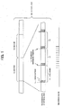
- the information recording medium in FIG. 1 is an optical disc 100 capable of recording the information with high-density, such as the DVD-RW and the DVD+RW.
- FIG. 1 shows a schematic diagram of a recording structure of the optical disc 100.
- management of the recording data is performed by a unit of a physical sector 16.
- One sector 16 includes plural sync frames 12, as shown in a middle portion in FIG. 1.
- one sector 16 includes twenty-six sync frames 12, and further one ECC (Error Correcting Code) unit, which is not shown, includes sixteen sectors 16.
- ECC Error Correcting Code
- the recording data to be recorded on the optical disc 100 is divided by the unit of the sync frame 12 as an information unit in advance. It is noted that a length of one sync frame 12 is 1488 times as long as a unit length (hereafter, it is indicated as "T") corresponding to a bit interval which is defined by a recording format at the time of recording the recording data.
- a head portion of one sync frame 12 includes a sync pattern 14 as the sync pattern.
- the sync pattern 14 is used for establishing synchronization for each sync frame 12.
- a position of a top pit of an LPP (Land Pre-pit) preformed on the optical disc 100 indicates a recording reference position 10 at the time of recording the information on the optical disc 100.
- the data is recorded so that the sync pattern 14 of the recording data corresponds to the recording reference position 10 on the optical disc 100. Therefore, by performing a phase correction of a recording clock on the basis of the position of the LPP, additional-recording and rewriting which start highly accurate recording by minimizing a link from the end of the recorded area become possible.
- the sync pattern 14 has the length of 14T, for example.
- the data is recorded on the optical disc 100.
- the recording clock is synchronized with the recording reference position 10 on the optical disc 100, and on the basis of the recording clock, the recording is performed so that the sync pattern 14 of the recording data corresponds to the recording reference position 10.
- FIG. 2A the recording structures shown in FIGS. 2A to 2C are identical to the recording structure of the optical disc 100 shown in the middle portion in FIG. 1, and the data to be recorded is recorded from the left side to the right side in FIGS. 2A to 2C.
- the explanation will be given by assuming the rewritable-type recording medium, such as the DVD-RW, the DVD+RW and the like, as the optical disc 100.
- the recording method shown in FIG. 2A adopts a method of recording the data by randomly shifting the recording start position on the optical disc 100 with respect to the recording reference position 10.
- the recording is performed by shifting the recording start position of overwriting data 20 with respect to the recording reference position 10 by a shift quantity ⁇ (i.e., ⁇ is a fixed value) which is randomly determined.
- the recording is continued by maintaining the shift quantity ⁇ until the recording of one recording data is completed.
- the shift quantity ⁇ is newly determined by using a random number and the like, and the recording is started.
- the method of recording the data by shifting the recording start position of the overwriting data 20 in the direction of the recording on the optical disc 100 (from inside to outside) is shown, but the recording start position may be shifted in the opposite direction.
- the shift quantity ⁇ is determined at the beginning, and the recording is performed with the shift quantity ⁇ fixed, while one recording data is recorded. Namely, while one recording data is recorded, the recording is performed in a state that the position of the sync pattern 14 is shifted with respect to the recording reference position 10 by the shift quantity ⁇ .
- the shift quantity ⁇ the value is determined so that the recording start position is within an LPP signal included in the optical disc 100. Therefore, the shift quantity ⁇ can be set to the value around ⁇ 5T at the maximum on the basis of the recording reference position 10, for example.
- a horizontal axis indicates time
- a vertical axis indicates a shift quantity X between the recording start position of the recording data and the recording reference position 10.
- a straight line A indicates the shift quantity between the recording start position of the data which has been recorded (hereafter, it is just called "recorded data") and the recording reference position 10.
- the straight line A indicates that the recording start position is shifted with respect to the recording reference position 10 by a shift quantity L, and that the shift quantity does not vary with regard to time.
- shift quantity "L” indicates a maximum value that the recording start position can be shifted with respect to the recording reference position 10, i.e., a maximum shift quantity.
- a hatched area 31 indicates a range within which the shift quantity of the recording start position of the recorded data with respect to the recording reference position 10 can be.
- a straight line B indicates the shift quantity of the recording start position of the recording data which is currently recorded (hereafter, it is just called "recording data") with respect to the recording reference position 10.
- the straight line B indicates a case that the recording start position is shifted with respect to the recording reference position 10 in the direction opposite to the recording direction by the maximum shift quantity L (shown as "-L" because of the shift in the opposite direction).
- An area 32 indicates a range within which the shift quantity of the recording start position of the recording data with respect to the recording reference position 10 canbe.
- a linking portion 15 is a portion at which the above-mentioned areas 31 and 32 are overlapped with each other. Namely, the linking portion 15 means a link between the recorded data and the recording start position of the recording data.
- the recorded data and the recording start position of the recording data are shifted by the double of the maximum shift quantity L at the maximum, i.e., by 2L.
- L the maximum shift quantity
- the probability that processing accuracy, such as reading of the recorded data, is affected becomes higher, e.g., establishing the synchronization becomes more difficult.
- the present invention adopts a recording method for solving the above-mentioned problem.
- a recording method according to a first embodiment of the present invention will be explained below.
- the recording method sets the recording start position on the optical disc 100 to the recording reference position 10 at the time of starting the recording, and gradually shifts the position of the sync pattern 14 of the recording data from the recording reference position 10 afterward.
- the shift quantity X (X is a variable) reaches the predetermined shift quantity ⁇ , the recording is continued with the shift quantity X fixed to the shift quantity ⁇ .
- the recording is continued with gradually increasing the shift quantity X until the shift quantity X between the position of the sync pattern 14 in the recording data and the recording reference position 10 on the optical disc 100 reaches the predetermined shift quantity ⁇ .
- FIG. 2B shows an example of the recording by shifting the position of the sync pattern 14 in the recording direction of the optical disc 100, which is backward with respect to the recording reference position 10.
- FIG. 2C shows an example of the recording by shifting the position of the sync pattern 14 of the recording data in the direction opposite to the recording direction of the optical disc 100, which is forward with respect to the recording reference position 10.
- the recording is started so that the sync pattern 14 of the overwriting data 20 corresponds to the recording reference position 10 on the optical disc 100, and then the recording is continued with gradually decreasing the shift quantity X until the shift quantity X between the position of the sync pattern 14 and the recording reference position 10 reaches the predetermined shift quantity ⁇ , which is minus in the case.
- the recording of the overwriting data 20 is performed with the shift quantity X fixed to the quantity ⁇ .
- the maximum value of the shift between the recorded data andthe recording start position of the recording data can be smaller than 2L in the area inwhich different recording data are overlapped with each other on the optical disc 100.
- the horizontal axis indicates time
- the vertical axis indicates the shift quantity X between the recording start position of the recording data and the recording reference position 10.
- the straight line A indicates the shift quantity X between the recording start position of the recorded data and the recording reference position 10
- the recording start position of the recorded data is shifted by the maximum value L in the recording direction in the example.
- the hatched area 31 shows the range within which the shift quantity X between the recording start position of the recorded data and the recording reference position 10 can be.
- a line segment C indicates the shift quantity between the recording start position of the recording data and the recording reference position 10.
- the recording of the recording data by the line segment C starts from the position at which the sync pattern 14 corresponds to the recording reference position 10, and the position of the sync pattern 14 of the recording data is linearly shifted with respect to the recording reference position 10 (in the example, the position of the sync pattern 14 is shifted in the direction opposite to the recording direction) afterward.
- the shift quantity X reaches the quantity "-L”
- the recording is continued with the shift quantity fixed to the quantity -"L”.
- An area 33 shows the range within which the shift quantity X between the sync pattern 14 of the recording data and the recording reference position 10 can be.
- the linking portion 15 is the portion at which the areas 31 and 33 are overlapped with each other, and it means the link between the recorded data and the recording data.
- the shift quantity X between the position of the sync pattern 14 of the recorded data and the recording start position of the recording data is L at the maximum.
- the shift between the position of the sync pattern 14 of the recorded data and the recording start position of the recording data is twice as large as L at the maximum in the above-mentioned normal method, the shift can be half in the recording method according to the present invention. This is because the recording is started from the recording reference position 10 on the optical disc 100, and the recording is continued by gradually shifting the recording start position.
- the recording method according to the present embodiment in the rewritable-type recording medium, the number of possible rewriting can be improved with the accuracy maintained at the time of reading the recording data.
- FIG. 4 An upper portion in FIG. 4 shows the recorded data which is recorded on the optical disc 100, and a lower portion in FIG. 4 shows the recording clock which is used at the time of the recording.
- the overwriting data 20 is indicated by diagonal lines.
- the overwriting data 20 is identical to the above-mentioned overwriting data 20, and it is assumed that the recording of the overwriting data 20 starts from the recording reference position 10 on the optical disc 100.
- a period of the recording clock i.e., time width
- T a period of the recording clock which is used for the recording of the recorded data
- the recording when the new data is recorded on the optical disc 100, the recording is started by making the sync pattern 14 of the recording data correspond to the recording reference position 10 on the optical disc 100 at the time of starting the recording, and the recording is continued by gradually shifting, up to the predetermined shift quantity ⁇ , the position of the sync pattern 14 of the recording signal with respect to the recording reference position 10 afterward. Since a number of the recording clocks is identical in one sync frame 12, the period of the recording clock is gradually varied. Concretely, as shown in FIG. 4, the period of the recording clock gradually increases in the recording direction, from (T+a) to (T+b) and then to (T+c) : (a ⁇ b ⁇ c).
- the shift quantity X between the position of the sync pattern 14 of the recording signal and the recording reference position 10 reaches the predetermined shift quantity ⁇ .
- the recording is continued by fixing the period of the recording clock to the original period T.
- the horizontal axis indicates time
- the vertical axis indicates the shift quantity X of the sync pattern 14 of the data to be recorded.
- the recording is continued with the shift quantity X fixed to the predetermined shift quantity ⁇ afterward.
- the process of gradually shifting the position of the sync pattern 14 of the data to be recorded can be executed by varying a control voltage which a VCO controller 209 explained later supplies to a recording clock generating unit 208.
- the position of the sync pattern 14 corresponds to the recording reference position 10 on the optical disc 100 at the time of starting the recording.
- the shift between the recorded data and the recording start position of the recording data can be smaller than the double of the maximum shift quantity L.
- the shift between the recorded data and the recording start position of the recording data can be smaller than the double of the maximum shift quantity L.
- a recording method according to a second embodiment is based on the above-mentioned aspect.
- the horizontal axis indicates time
- the vertical axis indicates the shift quantity X between the position of the sync pattern 14 of the recording data and the recording reference position 10.
- the straight line A indicates the time variation of the shift quantity X between the position of the sync pattern 14 of the recorded data and the recording reference position 10, and it indicates that the position of the sync pattern 14 of the recorded data is regularly shifted with respect to the recording reference position 10 byL.
- a hatched area 30 indicates the range within which the position of the sync pattern 14 of the recorded data with respect to the recording reference position 10 can be.
- a line segment D shows an example that the recording is performed on a condition that the position of the sync pattern 14 is shifted with respect to the recording reference position 10 in the direction opposite to the recording direction by ⁇ , at the time of starting the recording.
- the line segment D shows an example that the recording of the recording data is started from a position which is shifted from the recording reference position 10 on the optical disc 100 by ⁇ , the position of the sync pattern 14 of the recording signal is linearly shifted with respect to the recording reference position 10, and the recording is continued with the shift quantity X fixed to the maximum shift quantity L when the shift quantity X reaches the maximum shift quantity L.
- An area 35 shows the range within which the recording start position of the recording data with respect to the recording reference position 10 can be.
- the linking portion 15 is the portion at which the above-mentioned areas 30 and 35 are overlapped with each other.
- the shift quantity between the recording start positions of the recorded data and the recording data is (L+ ⁇ ) at the maximum. Since ⁇ is chosen from the value smaller than the maximum shift quantity L, the above-mentioned shift quantity (L+ ⁇ ) is smaller than the double of L. Therefore, by the recording method according to the second embodiment, without decreasing the accuracy of reading the recorded data in the overwriting portion, the number of possible rewriting to the rewritable-type recording medium can be improved, too.
- the recording is performed so that the position of the sync pattern 14 corresponds to the recording reference position 10 at the time of starting the recording, and the position of the sync pattern 14 is gradually shifted with respect to the recording reference position 10 afterward.
- the shift quantity X between the position of the sync pattern 14 and the recording reference position 10 is always varied, and even if the predetermined time goes by (i.e., even if the shift quantity X reaches the predetermined shift quantity ⁇ ), the shift quantity X is not fixed to the predetermined shift quantity ⁇ afterward.
- FIG. 7 shows a concrete example of the recording method according to the third embodiment.
- the horizontal axis indicates time
- the vertical axis indicates the shift quantity X between the position of the sync pattern 14 and the recording reference position 10.
- the straight line A is the position of the sync pattern 14 of the recorded data, and the position is shifted with respect to the recording reference position 10 by the maximum shift quantity L in the case.
- a curved line E indicates the time variation of the shift quantity X between the position of the sync pattern 14 of the recording data and the recording reference position 10.
- the recording is started by making the position of the sync pattern 14 correspond to the recording reference position 10 on the optical disc 100, and the recording is continued by non-linearly varying the shift quantity X with respect to the recording reference position 10 for each sync pattern 14 of the recording data afterward. It is noted that the shift quantity X is varied within the range of ⁇ L. In addition, the shift quantity X is determined by generating the randomnumber for each sync pattern 14 of the data to be recorded, for example.
- the recording method according to the third embodiment since the recording is performed by generating the random number for each sync pattern 14 and randomly shifting the position of the sync pattern 14 with respect to the recording reference position 10, a probability that the recording start position of the new recording data coincides with the position of the sync pattern 14 of the recorded data becomes small. Thereby, the number of possible rewriting can be increased.
- the recording method according to the present embodiment when the different data is rewritten, the shift of the recording position can be also smaller than the double of the maximum shift quantity L at the maximum.
- the identical effect can be obtained without making the position of the sync pattern 14 correspond the recording reference position 10 on the optical disc 100.
- the shift of the recording position can be smaller than the double of the maximum shift quantity L at the maximum.
- FIG. 8 is a block diagram showing a schematic configuration of an information recording and reproducing apparatus 200.
- the information recording and reproducing apparatus 200 can record the information such as the image data, the contents and the like, on the optical disc 100 such as the DVD-RW and the like, and can further reproduce the information which is recorded on the optical disc 100 such as a DVD-ROM and the like.
- the optical disc 100 the rewritable-type recording medium capable of repeated recording, such as the DVD-RW and the DVD+RW, is applicable.
- the optical pickup 202 outputs an RF (Radio Frequency) signal 301 corresponding to a reflected light of a light beam at the time of the recording and the reproduction.
- RF Radio Frequency
- a pre-amplifier 206 amplifies the RF signal 301 outputted from the optical pickup 202, and outputs an amplified RF signal 302 to a demodulating unit 207.
- the demodulating unit 207 generates a wobble frequency signal, a tracking error signal, a focus error signal and the like from the RF signal 302, and outputs them.
- the demodulating unit 207 generates a disc reference position signal 303 from the RF signal 301 outputted from the preamplifier 206, on the basis of a prepit format position of the prepit and the like, and supplies it to the recording clock generating unit 208.
- a CPU 210 includes a memory (not shown) and the like, and the memory stores a voltage pattern to be supplied to a VCO controller 209.
- the voltage pattern can be a pattern which increases and'decreases stepwise from a constant voltage value, for example, as shown in FIG. 5.
- the VCO controller 209 supplies the voltage pattern, which is supplied from the CPU 210, to the recording clock generating unit 208 as a control voltage signal 304.
- the recording clock generating unit 208 includes a VCO (Voltage Controlled Oscillator). Also, the recording clock generating unit 208 generates a recording clock signal 305 which has a frequency corresponding to the control voltage signal 304 supplied from the VCO controller 209 and which is synchronized with the disc reference position signal 303 supplied from the demodulating unit 207, and supplies it to a recording gate signal generating unit 212.
- the recording gate signal generating unit 212 generates a recording gate signal 306 which is synchronized with the recording clock signal 305, and supplies it to the modulating unit 204.
- the buffer 203 temporarily stores input data which is supplied via an interface (not shown) once.
- the input data 307 is data to be recorded on the optical disc 100, and the input data 307 which is inputted to the buffer 203 is supplied to the modulating unit 204.
- the modulating unit 204 applies the code-conversion to the input data 307. For example, when the optical disc 100 is the DVD-RW, the modulating unit 204 applies the code-conversion, such as 8-16 modulation, to the input data. Then, the modulating unit 204 gates the modulated signal by the recording gate signal 306 which is inputted from the recording gate signal generating unit 212, and supplies it to a laser drivingunit 205 as amodulating signal 308. Thereby, the modulating signal 308 which is outputted from the modulating unit 204 is synchronized with the recording clock 305.
- the code-conversion such as 8-16 modulation
- the frequency of the recording clock is gradually reduced and the period is increased until the shift quantity X between the position of the sync pattern 14 and the recording reference position 10 reaches the predetermined shift quantity ⁇ .
- the frequency of the recording clock is fixed and the period is maintained at the constant value T, after the shift quantity X reaches the predetermined shift quantity ⁇ .
- the VCO controller 209, the recording clock generating unit 208 and the recording gate signal generating unit 212 form a PLL (Phase Locked Loop) circuit. Namely, by the PLL circuit, the recording clock used for recording the data establishes a phase synchronization with the disc reference position signal corresponding to the prepit recorded on the optical disc 100.
- PLL Phase Locked Loop
- the laser driving unit 205 generates a driving signal 309 which adjusts a laser power on the basis of the modulating signal 308 supplied from the modulating unit 204, and supplies it to the optical pickup 202.
- the optical pickup 202 includes a laser diode (not shown), and controls emission of the laser diode on the basis of the driving signal 309 supplied from the laser driving unit 205 to record the data on the optical disc 100.
- the CPU 210 controls the above-mentioned respectivecomponents, and shifts the position of the sync pattern 14 of the recording data according to the present invention with respect to the recording reference position 10 while recording the recording data. It is noted that the CPU 210 can control the whole information recording and reproducing apparatus 200, in addition to the above-mentioned control, and can control and manage the above-mentioned transmission of the information among the respective components.
- FIG. 9 shows a flow chart of the data recording process.
- the method of recording the data according to the first embodiment is applied to an example shown in FIG. 9. Namely, at the time of starting the recording of the data, the recording is started by making the position of the sync pattern 14 of the recording data correspond to the recording reference position 10 on the optical disc 100, and the position of the sync pattern 14 of the recording data is gradually shifted with respect to the recording reference position 10 by the shift quantity X afterward. When the shift quantity X reaches the predetermined shift quantity ⁇ , the recording is continued with the predetermined shift quantity ⁇ maintained afterward.
- the CPU 210 mainly executes a process which will be explained below by controlling the respective units shown in FIG. 8.
- step S11 the CPU 210 generates a random number "k" in order to determine the predetermined shift quantity ⁇ which is used in a subsequent process. If the CPU 210 generates the random number k and determines the different shift quantity ⁇ at every time of recording the data by the predetermined unit, it is possible to reduce the probability that the positions of the sync patterns 14 of the recorded data and the recording data for rewriting are overlapped with each other at the time of rewriting the recording data. It is noted that the CPU 210 generates the random number k within the range of -1 ⁇ k ⁇ 1. When the random number k is determined, the process goes to step S12.
- step S12 the CPU 210 determines the predetermined shift quantity ⁇ on the basis of the random number k which is determined in step S11.
- the predetermined shift quantity ⁇ is calculated by multiplying the above-mentioned maximum shift quantity L and the random number k together.
- the memory and the like in the CPU 210 can store the value of the maximum shift quantity L in advance.
- step S13 the recording reference position 10 on the optical disc 100 is detected.
- the recording reference position 10 is the position of the LPP formed on the optical disc 100, for example. Therefore, in step S13, the demodulating unit 207 generates the disc reference position signal 303 from a reading signal of the optical disc 100. Then, the process goes to step S14.
- step S15 the process of gradually shifting the position of the sync pattern 14 of the recording signal with respect to the recording reference position 10 on the optical disc 100 is executed.
- the CPU 210 controls the VCO controller 209 and varies the time width of the recording clock. Thereby, for example, as shown in FIG. 5, the CPU 210 shifts the position of the sync pattern 14 of the recording signal by ⁇ .
- the process goes to step S16.
- step S16 the CPU 210 calculates the shift quantity X between the position of the sync pattern 14 of the recording data and the recording reference position 10 on the optical disc 100, and determines whether the shift quantity X is equal to or larger than the predetermined shift quantity ⁇ or not. If the calculated shift is equal to or larger than the predetermined shift quantity ⁇ , the process goes to step S17, and if the calculated shift quantity X is smaller than the predetermined shift quantity ⁇ , the process returns to step S15.
- step S16 When the shift quantity X is smaller than the predetermined shift quantity ⁇ (step S16; No), the CPU 210 executes the process of further shifting the position of the sync pattern 14 of the recording signal with respect to the recording reference position 10 on the optical disc 100 in step S15. For example, as shown in FIG. 5, the CPU 210 can further shift the position of the sync pattern 14 of the recording signal by ⁇ . Like this, by repeating the processes in steps S15 and S16, the CPU 210 gradually increases the shift quantity X between the position of the sync pattern 14 of the recording signal and the recording reference position 10 up to the predetermined shift quantity ⁇ .
- step S16 when the position of the sync pattern 14 of the recording signal is shifted with respect to the recording reference position 10 by the quantity equal to or larger than the predetermined shift quantity ⁇ (step S16; Yes), the shift quantity X is fixed to the predetermined shift quantity ⁇ in step S17. Namely, the position of the sync pattern 14 is not shifted any more. Therefore, the subsequent recording is performed with the shift quantity X being fixed to the shift quantity ⁇ . Then, the process goes to step S18.
- step S18 the CPU 210 determines whether the data to be recorded is at an end position or not. If the recording data is at the end position, the process goes out of the flow chart and ends. On the other hand, if the recording data is not at the end position, the process returns to step S17, and the recording is continued in the state that the shift quantity between the position of the sync pattern 14 of the recording data and the recording reference position 10 is maintained at the shift quantity ⁇ .
- the shift between the recording position of the sync pattern 14 of the recorded data and the recording position of the sync pattern of the recording data for rewriting can be set to zero.
- the accuracy of the process of reproducing and recording on the optical disc 100 can be prevented from being deteriorated.
- the recording positions of the sync patterns 14 of the recording data are different dependently on the recording data, the number of possible rewriting on the optical disc can also be improved.
Landscapes
- Engineering & Computer Science (AREA)
- Signal Processing (AREA)
- Optical Recording Or Reproduction (AREA)
- Signal Processing For Digital Recording And Reproducing (AREA)
Abstract
Description
Claims (11)
- An information recording and reproducing apparatus (200) which records information on a rewritable-type recording medium (100), comprising:wherein the recording unit records the recording data by making a sync pattern (14) of the recording data correspond to the recording reference position (10) at a time of starting of recording, and records the recording data by shifting the sync pattern (14) of the recording data with respect to the recording reference position (10) after starting the recording.a recording reference position detecting unit (207, 210) which detects a recording reference position (10) on the recording medium; anda recording unit (202, 205, 210) which records recording data on the basis of the detected recording reference position,
- The information recording and reproducing apparatus (200) according to claim 1, wherein the recording unit increases a shift quantity (X) between the sync pattern (14) of the recording data and the recording reference position (10) up to a predetermined shift quantity (α) after starting the recording, and performs the recording with the shift quantity (X) maintained at the predetermined shift quantity (α) after the shift quantity reaches the predetermined shift quantity (α).
- The information recording and reproducing apparatus (200) according to claim 2, wherein the recording unit comprises:a unit (210) which detects the shift quantity (X) between the sync pattern (14) of the recording data and the recording reference position (10);a unit (210) which gradually increases the shift quantity (X) when the detected shift quantity (X) is smaller than the predetermined shift quantity (α), and which maintains the shift quantity (X) at the predetermined shift quantity (α) when the detected shift quantity (X) is identical to the predetermined shift quantity (α).
- The information recording and reproducing apparatus (200) according to claim 1, wherein the recording unit performs the recording while varying the shift quantity (X) between the sync pattern (14) of the recording data and the recording reference position (10) within a range of the predetermined shift quantity (α) after starting the recording.
- The information recording and reproducing apparatus (200) according to claim 2, wherein the recording unit randomly determines the predetermined shift quantity.
- An information recording and reproducing apparatus (200) which records information on a rewritable-type recording medium (100), comprising:wherein the recording unit records the recording data by shifting a sync pattern (14) of the recording data with respect to the recording reference position (10) by an initial shift quantity (β) at a time of starting of recording, and records the recording data by shifting the sync pattern (14) of the recording data with respect to the recording reference position (10) within a range (α) of a predetermined shift quantity after starting the recording; anda recording reference position detecting unit (207, 210) which detects a recording reference position (10) on the recording medium; anda recording unit (202, 205, 210) which records recording data on the basis of the detected recording reference position (10),
wherein the initial shift quantity (β) is smaller than the predetermined shift quantity (α). - The information recording and reproducing apparatus (200) according to claim 6, wherein the recording unit randomly determines the predetermined shift quantity (X).
- An information recording method which records information on a rewritable-type recording medium (100), comprising:wherein the recording process records the recording data by making a sync pattern (14) of the recording data correspond to the recording reference position (10) at a time of starting of recording, and records the recording data by shifting the sync pattern (14) of the recording data with respect to the recording reference position (10) after starting the recording.an recording reference position detecting process which detects a recording reference position (10) on the recording medium; anda recording process which records recording data on the basis of the detected recording reference position,
- An information recording method which records information on a rewritable-type recording medium (100), comprising:wherein the recording process records the recording data by shifting a sync pattern (14) of the recording data with respect to the recording reference position (10) by an initial shift quantity (β) at a time of starting of recording, and records the recording data by shifting the sync pattern (14) of the recording data with respect to the recording reference position (10) within a range (α) of a predetermined shift quantity after starting the recording; anda recording reference position detecting process which detects a recording reference position (10) on the recording medium; anda recording process which records recording data on the basis of the detected recording reference position,
wherein the initial shift quantity (β) is smaller than the predetermined shift quantity(α). - An information recording program executed by an information recording apparatus comprising a computer for recording information on a rewritable-type recording medium (100), the program making the computer function as:wherein the recording unit records the recording data by making a sync pattern (14) of the recording data correspond to the recording reference position (10) at a time of starting of recording, and records the recording data by shifting the sync pattern (14) of the recording data with respect to the recording reference position (10) after starting the recording.a recording reference position detecting unit (207, 210) which detects a recording reference position (10) on the recording medium; anda recording unit (202, 204, 210) which records recording data on the basis of the detected recording reference position,
- An information recording program executed in an information recording apparatus comprising a computer for recording information on a rewritable-type recording medium (100), the program making the computer function as:wherein the recording unit records the recording data by shifting a sync pattern (14) of the recording data with respect to the recording reference position (10) by an initial shift quantity (β) at a time of starting of recording, and records the recording data by shifting the sync pattern (14) of the recording data with respect to the recording reference position (10) within a range of a predetermined shift quantity (a) after starting the recording; anda recording reference position detecting unit (207, 210) which detects a recording reference position (10) on the recording medium; anda recording unit (202, 204, 210) which records recording data on the basis of the detected recording reference position,
wherein the initial shift quantity (β) is smaller than the predetermined shift quantity (α).
Applications Claiming Priority (2)
| Application Number | Priority Date | Filing Date | Title |
|---|---|---|---|
| JP2003360815 | 2003-10-21 | ||
| JP2003360815A JP4200077B2 (en) | 2003-10-21 | 2003-10-21 | Information recording apparatus, information recording method, and information recording program |
Publications (2)
| Publication Number | Publication Date |
|---|---|
| EP1526542A2 true EP1526542A2 (en) | 2005-04-27 |
| EP1526542A3 EP1526542A3 (en) | 2007-05-02 |
Family
ID=34386479
Family Applications (1)
| Application Number | Title | Priority Date | Filing Date |
|---|---|---|---|
| EP04256431A Withdrawn EP1526542A3 (en) | 2003-10-21 | 2004-10-19 | Information recording apparatus, information recording method and information recording program |
Country Status (3)
| Country | Link |
|---|---|
| US (1) | US20050111317A1 (en) |
| EP (1) | EP1526542A3 (en) |
| JP (1) | JP4200077B2 (en) |
Cited By (1)
| Publication number | Priority date | Publication date | Assignee | Title |
|---|---|---|---|---|
| CN111145790A (en) * | 2020-01-23 | 2020-05-12 | 广东紫晶信息存储技术股份有限公司 | Holographic optical disk reading method and device for high-speed parallel reproduction |
Families Citing this family (3)
| Publication number | Priority date | Publication date | Assignee | Title |
|---|---|---|---|---|
| TW200741679A (en) * | 2005-11-17 | 2007-11-01 | Koninkl Philips Electronics Nv | A method and system for recording data by a plurality of laser beams on an optical disc |
| DE202008010463U1 (en) * | 2007-08-07 | 2009-04-23 | Plds Taiwan (Philips & Lite-On Digital Solutions Corporation) | Optical data carrier and a device for recording on a disc-shaped optical data carrier |
| TWI651719B (en) * | 2016-05-27 | 2019-02-21 | 日商新力股份有限公司 | Disc-shaped recording medium, recording device, recording method, reproducing device, and reproducing method |
Family Cites Families (7)
| Publication number | Priority date | Publication date | Assignee | Title |
|---|---|---|---|---|
| JPH0810489B2 (en) * | 1987-03-19 | 1996-01-31 | 松下電器産業株式会社 | Optical disc recording method and optical disc device |
| US5216657A (en) * | 1989-09-19 | 1993-06-01 | Matsushita Electric Industrial Co., Ltd. | Method and apparatus for timing variable optical information recording |
| HU229820B1 (en) * | 1996-02-16 | 2014-08-28 | Koninkl Philips Electronics Nv | Device for recording an information carrier, method and information carrier therefor |
| JP3023310B2 (en) * | 1996-05-31 | 2000-03-21 | 松下電器産業株式会社 | Recording / reproducing method and recording / reproducing apparatus for optical information recording medium |
| JPH10124873A (en) * | 1996-10-23 | 1998-05-15 | Sony Corp | Signal recording method and signal recording / reproducing device |
| JP3551224B2 (en) * | 1997-03-25 | 2004-08-04 | 富士通株式会社 | Magneto-optical reproducing method and apparatus used for implementing the method |
| CN1636244B (en) * | 2002-08-07 | 2010-11-10 | 松下电器产业株式会社 | Recording device and recording method |
-
2003
- 2003-10-21 JP JP2003360815A patent/JP4200077B2/en not_active Expired - Fee Related
-
2004
- 2004-10-19 EP EP04256431A patent/EP1526542A3/en not_active Withdrawn
- 2004-10-21 US US10/969,189 patent/US20050111317A1/en not_active Abandoned
Cited By (1)
| Publication number | Priority date | Publication date | Assignee | Title |
|---|---|---|---|---|
| CN111145790A (en) * | 2020-01-23 | 2020-05-12 | 广东紫晶信息存储技术股份有限公司 | Holographic optical disk reading method and device for high-speed parallel reproduction |
Also Published As
| Publication number | Publication date |
|---|---|
| US20050111317A1 (en) | 2005-05-26 |
| JP2005129101A (en) | 2005-05-19 |
| JP4200077B2 (en) | 2008-12-24 |
| EP1526542A3 (en) | 2007-05-02 |
Similar Documents
| Publication | Publication Date | Title |
|---|---|---|
| US6522608B1 (en) | Information recording apparatus for writable recording media | |
| EP0962930A1 (en) | Apparatus for and method of adding information onto recording medium that enables additional recording | |
| US6891784B2 (en) | Apparatus and method for re-executing pre-pit detection if pre-pits are not detected after changing reference level | |
| US7012865B2 (en) | Recording apparatus and recording method | |
| EP1526542A2 (en) | Information recording apparatus, information recording method and information recording program | |
| JP4357890B2 (en) | Land pre-pit detection apparatus and method | |
| JP2003091819A (en) | Optical disk drive | |
| US7397751B2 (en) | Optical disk apparatus, method of recording information, and information recording medium | |
| JP3792169B2 (en) | Optical recording medium recording apparatus | |
| JP4086414B2 (en) | Information recording method and information recording apparatus | |
| JP2005122882A (en) | Recording method on optical recording medium having wobble header area formed | |
| JP4132525B2 (en) | Information recording device | |
| JP4387266B2 (en) | Optical disk device | |
| JP4621550B2 (en) | Error correction device for optical disk device | |
| JP2000298955A (en) | Information recording device, and information recording method | |
| RU2262141C2 (en) | Optical disk and physical address format | |
| JP3486388B2 (en) | Information recording apparatus and information recording method | |
| EP1189232A2 (en) | Information transmission and recording in a content distributing system | |
| JP2006127699A (en) | Optical disk recording/reproducing device | |
| JP2004047087A (en) | Information recorder and information recording method | |
| JP2008004197A (en) | Optical disk recording device |
Legal Events
| Date | Code | Title | Description |
|---|---|---|---|
| PUAI | Public reference made under article 153(3) epc to a published international application that has entered the european phase |
Free format text: ORIGINAL CODE: 0009012 |
|
| AK | Designated contracting states |
Kind code of ref document: A2 Designated state(s): AT BE BG CH CY CZ DE DK EE ES FI FR GB GR HU IE IT LI LU MC NL PL PT RO SE SI SK TR |
|
| AX | Request for extension of the european patent |
Extension state: AL HR LT LV MK |
|
| PUAL | Search report despatched |
Free format text: ORIGINAL CODE: 0009013 |
|
| AK | Designated contracting states |
Kind code of ref document: A3 Designated state(s): AT BE BG CH CY CZ DE DK EE ES FI FR GB GR HU IE IT LI LU MC NL PL PT RO SE SI SK TR |
|
| AX | Request for extension of the european patent |
Extension state: AL HR LT LV MK |
|
| AKX | Designation fees paid | ||
| REG | Reference to a national code |
Ref country code: DE Ref legal event code: 8566 |
|
| STAA | Information on the status of an ep patent application or granted ep patent |
Free format text: STATUS: THE APPLICATION IS DEEMED TO BE WITHDRAWN |
|
| 18D | Application deemed to be withdrawn |
Effective date: 20071103 |