EP1526414A1 - Hologram recording/reproducing system - Google Patents
Hologram recording/reproducing system Download PDFInfo
- Publication number
- EP1526414A1 EP1526414A1 EP03766617A EP03766617A EP1526414A1 EP 1526414 A1 EP1526414 A1 EP 1526414A1 EP 03766617 A EP03766617 A EP 03766617A EP 03766617 A EP03766617 A EP 03766617A EP 1526414 A1 EP1526414 A1 EP 1526414A1
- Authority
- EP
- European Patent Office
- Prior art keywords
- data
- recording medium
- unit
- light
- recording
- Prior art date
- Legal status (The legal status is an assumption and is not a legal conclusion. Google has not performed a legal analysis and makes no representation as to the accuracy of the status listed.)
- Withdrawn
Links
- 238000006243 chemical reaction Methods 0.000 claims abstract description 24
- 230000001427 coherent effect Effects 0.000 claims abstract description 7
- 239000000463 material Substances 0.000 claims abstract description 6
- 238000011144 upstream manufacturing Methods 0.000 claims description 2
- 230000003287 optical effect Effects 0.000 description 12
- 230000015572 biosynthetic process Effects 0.000 description 2
- 239000004973 liquid crystal related substance Substances 0.000 description 2
- 229920000642 polymer Polymers 0.000 description 2
- 239000013078 crystal Substances 0.000 description 1
- 238000001514 detection method Methods 0.000 description 1
- GQYHUHYESMUTHG-UHFFFAOYSA-N lithium niobate Chemical compound [Li+].[O-][Nb](=O)=O GQYHUHYESMUTHG-UHFFFAOYSA-N 0.000 description 1
- 239000010409 thin film Substances 0.000 description 1
Images


Classifications
-
- G—PHYSICS
- G03—PHOTOGRAPHY; CINEMATOGRAPHY; ANALOGOUS TECHNIQUES USING WAVES OTHER THAN OPTICAL WAVES; ELECTROGRAPHY; HOLOGRAPHY
- G03H—HOLOGRAPHIC PROCESSES OR APPARATUS
- G03H1/00—Holographic processes or apparatus using light, infrared or ultraviolet waves for obtaining holograms or for obtaining an image from them; Details peculiar thereto
- G03H1/26—Processes or apparatus specially adapted to produce multiple sub- holograms or to obtain images from them, e.g. multicolour technique
- G03H1/2645—Multiplexing processes, e.g. aperture, shift, or wavefront multiplexing
- G03H1/265—Angle multiplexing; Multichannel holograms
-
- G—PHYSICS
- G03—PHOTOGRAPHY; CINEMATOGRAPHY; ANALOGOUS TECHNIQUES USING WAVES OTHER THAN OPTICAL WAVES; ELECTROGRAPHY; HOLOGRAPHY
- G03H—HOLOGRAPHIC PROCESSES OR APPARATUS
- G03H1/00—Holographic processes or apparatus using light, infrared or ultraviolet waves for obtaining holograms or for obtaining an image from them; Details peculiar thereto
- G03H1/04—Processes or apparatus for producing holograms
- G03H1/16—Processes or apparatus for producing holograms using Fourier transform
-
- G—PHYSICS
- G03—PHOTOGRAPHY; CINEMATOGRAPHY; ANALOGOUS TECHNIQUES USING WAVES OTHER THAN OPTICAL WAVES; ELECTROGRAPHY; HOLOGRAPHY
- G03H—HOLOGRAPHIC PROCESSES OR APPARATUS
- G03H1/00—Holographic processes or apparatus using light, infrared or ultraviolet waves for obtaining holograms or for obtaining an image from them; Details peculiar thereto
- G03H1/26—Processes or apparatus specially adapted to produce multiple sub- holograms or to obtain images from them, e.g. multicolour technique
-
- G—PHYSICS
- G11—INFORMATION STORAGE
- G11B—INFORMATION STORAGE BASED ON RELATIVE MOVEMENT BETWEEN RECORD CARRIER AND TRANSDUCER
- G11B7/00—Recording or reproducing by optical means, e.g. recording using a thermal beam of optical radiation by modifying optical properties or the physical structure, reproducing using an optical beam at lower power by sensing optical properties; Record carriers therefor
- G11B7/004—Recording, reproducing or erasing methods; Read, write or erase circuits therefor
- G11B7/0065—Recording, reproducing or erasing by using optical interference patterns, e.g. holograms
-
- G—PHYSICS
- G03—PHOTOGRAPHY; CINEMATOGRAPHY; ANALOGOUS TECHNIQUES USING WAVES OTHER THAN OPTICAL WAVES; ELECTROGRAPHY; HOLOGRAPHY
- G03H—HOLOGRAPHIC PROCESSES OR APPARATUS
- G03H2260/00—Recording materials or recording processes
- G03H2260/50—Reactivity or recording processes
- G03H2260/54—Photorefractive reactivity wherein light induces photo-generation, redistribution and trapping of charges then a modification of refractive index, e.g. photorefractive polymer
Definitions
- the present invention relates to a holographic recording medium and a recording and reproducing system utilizing this.
- hologram recording systems have been known as a digital information recording system that utilizes the principle of hologram.
- a feature of this system is to record an information signal into a recording medium as a change in a refractive index.
- Photorefractive materials such as a single crystal lithium niobate or the like are used for the recording medium.
- data can be recorded and reproduced in the units of two-dimensional plane pages, and multiplexed recording is possible by using a plurality of pages. The outline of the recording medium system is explained below.
- a laser light beam 12 emanating from a laser light source 11 is split into lights 12a and 12b by a beam splitter 13, as shown in Fig. 1.
- the light 12a is shaped into a substantially collimated light, the beam diameter of which is enlarged by a beam expander BX, and is projected onto a spatial light modulator (SLM) such as a transmissive-type TFT liquid crystal display (Thin Film Transistor Liquid Crystal Display) (hereinafter also referred to as "LCD”) panel or the like.
- SLM spatial light modulator
- LCD Thin Film Transistor Liquid Crystal Display
- An encoder 25 converts a digital data to be recorded in a recording medium 10 into an bright and dark dot-pattern image on a plane and rearranges it into a data array of, for example, 480 vertical bits ⁇ 640 horizontal bits.
- the encoder generates a unit-page series data and sends out the data to the spatial light modulator SLM.
- the light 12a When the light 12a transmits through the spatial light modulator SLM, it is light-modulated and turned into a signal light containing a data signal component.
- the signal light 12a containing the dot pattern signal component passes through a Fourier transform lens 16, which is spaced apart by its focal distance f, and the dot pattern signal component is Fourier transformed. Then, the light is gathered into a recording medium 10.
- the light beam 12b split by the beam splitter 13 is guided as a reference light into the recording medium 10 by mirrors 18 and 19, and it intersects the light path of the signal light 12a within the recording medium 10, forming a light interference pattern.
- the entirety of the light interference pattern is recorded as a change in the refractive index (refractive index grating).
- refractive index grating refractive index grating
- inverse Fourier transform is performed to reproduce the dot pattern image.
- the light path of the signal light 12a is blocked by the spatial light modulator SLM so that only the reference light 12b is projected onto the recording medium 10.
- the reference light 12b is controlled by the mirror driven in the position and angle thereof with a combination of the rotation and linear movement so that the incident angle thereof results in the same as that of the reference light at the time when the page to be reproduced has been recorded.
- a reproduced light that reconstructs the recorded light interference pattern appears on a side of the recording medium 10 that is opposite the side thereof that is irradiated with the reference light 12b.
- the dot pattern image can be reconstructed. Further, this dot pattern image is received by a photo-detector 20 such as a charge coupled device (CCD) or the like at the focal distance position, and the image is reconverted into an electrical digital data signal. Thereafter, the data signal is sent to a decoder 26, and the original page data is reproduced.
- a photo-detector 20 such as a charge coupled device (CCD) or the like at the focal distance position
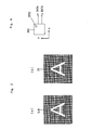
- the transmitted light for, for example, the portion of the image data "A" as shown in Fig. 2(a) that is displayed on the spatial light modulator SLM is Fourier-transformed and recorded into the recording medium as an interference pattern of Fourier transform pattern, and the image of the image data A that has been inverse Fourier-transformed as shown in Fig. 2(b) is reproduced on the CCD 20 from the recording medium illuminated with the reference light. Therefore, the conventional recording and reproducing system necessitates a CCD 20 that is similar to the spatial light modulator SLM with 480 vertical bits ⁇ 640 horizontal bits and has the same resolution.
- the precondition is that the recording and reproducing system uses a fixed conversion rule for the recording system and the reproducing system to perform recording and reproducing.
- the conventional recording and reproducing system it is required for the conventional recording and reproducing system to keep optical distortion, deviation of the signal image, or the like that occurs in the Fourier transform optical system, the inverse Fourier transform optical system, and other optical systems, within a predetermined specified value range.
- This requires such components as high-precision lenses or the like for the optical systems, and moreover a high-precision relative position adjustment is necessary.
- an expensive detector such as a CCD or the like is required in order to perform high-speed data transfer.
- an example of the problem that the present invention intends to solve is to provide a hologram recording and reproducing system that does not require an inverse Fourier lens.
- a hologram recording and reproducing system of the invention has a supporting unit for freely attachably supporting a recording medium (including a photosensitive material such as a photorefractive polymer, a hole burning material, a photochromic material, etc.); a signal light-generating unit for projecting a coherent light beam modulated according to a predetermined data into the recording medium and generating a refractive index grating by providing a three-dimensional light interference pattern in the recording medium; a detector unit for detecting and photoelectrically converting a diffracted light from the refractive index grating; and a demodulating unit for demodulating a predetermined data from an output from the detector unit, the hologram recording and reproducing system characterized in that: the detector unit has an intermediate data-generating unit for generating an intermediate data, and the demodulating unit has a conversion table in which the intermediate data and the predetermined data are uniquely associated, and demodulates the predetermined data by performing an operation based on a correlation in the conversion table.
- a recording medium including
- an intermediate data is reproduced in advance and the reproduced intermediate data is computed based on a correlation in a predetermined conversion table that has been stored in advance, to demodulate an original data, in the case in which conversion rules are different between the recording system and the reproducing system.
- the case in which the conversion rules are different between the recording system and the reproducing system is as follows.
- a Fourier transform recording is carried out by a Fourier transform lens optical system.
- the following cases are included: the case in which conversion is performed using not only the inverse Fourier transform lens optical system but also an additional optical system to obtain an intermediate data and demodulation is performed; and the case in which a detected intermediate data is inverse Fourier-transformed by a computer and a predetermined data is thereby demodulated instead of using the inverse Fourier transform lens.
- a conversion table is defined in advance.
- the conversion table are an inverse Fourier computing device, one in which a Fourier transform pattern in the vicinity of the Fourier plane is uniquely associated with a data that has not yet been Fourier-transformed, one in which a positional data that is output from a predetermined position sensor is uniquely associated with each of the data that are recorded in a reference data-holding hologram, etc.
- Various conversion tables are defined in advance for other recording medium formats, and the conversion tables are recorded in a non-volatile memory of the recording and reproducing system upon shipment. It is also possible to record the conversion tables in a rewritable memory.
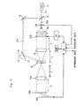
- Fig. 3 shows an example of a first embodiment of a recording and reproducing system according to the invention.
- the inverse Fourier transform lens is not used, as shown in Fig. 3; a light-receiving face of a photo-detector 200 such as a two-dimensional light sensor or the like is disposed in the vicinity of the Fourier plane FF, and a recording medium 10 is disposed in the upstream of the photo-detector 200, that is, between the photo-detector 200 and a Fourier transform lens 16.
- the recording and reproducing system has a similar configuration to that of the conventional one except that the system is equipped with the inverse Fourier computing device and a non-volatile memory ROM that is connected to a controller 30 and stores a conversion table in which a Fourier transform pattern in the vicinity of the Fourier plane is associated with a data that has not yet been Fourier transformed.
- the controller 30 computes a predetermined original data from a reproduced Fourier transform pattern according to the inverse Fourier computing device.
- the photo-detector 200 is sufficient as long as it can obtain the Fourier transform pattern as intermediate data, and the position of the photo-detector 200 may be in the vicinity of either the front or the back of the Fourier plane.
- a light beam emanating from a laser light source 11 is split by a beam splitter 13 into two beams, a signal light beam that propagates linearly and a reference light beam that deflects upward.
- the respective beams are guided to respective light paths of signal and reference light beam optical systems.
- the signal light beam 12a that has passed through the beam splitter 13 goes through a shutter 6a, a light beam expander BX, a spatial light modulator SLM, and a Fourier transform lens 16, and enters a recording medium 10.
- the time during which the signal light beam 12a is projected to the recording medium is controlled by the automatic shutter 6a, which is controlled by the controller 30, and the signal light beam is enlarged by the beam expander BX into a collimated light having a predetermined diameter.
- the spatial light modulator SLM is, for example, a transmissive LCD with a two-dimensional plane of 480 pixels vertically ⁇ 640 pixels horizontally, and converts the light beam from the beam expander BX into signal light according to a digital recording data supplied from an encoder 25.
- the data displayed on the spatial light modulator SLM is the image data A shown in Fig. 2(a) and light transmits through that portion, turning to signal light
- the image data A is Fourier-transformed and a Fourier transform pattern as shown in Fig. 4 is generated in the vicinity of the Fourier plane FF.
- the data is recorded in the recording medium 10 as an interference pattern of the reference light and the signal light that has not yet reached the Fourier transform pattern.
- a data is spatial-modulated according to a recording page data into a two-dimensional dot pattern in which each pixel is transmissive or non-transmissive; thereafter, it is Fourier-transformed by the Fourier transform lens 16, gathered into the recording medium 10, and formed into a point image having a high light intensity on the Fourier plane FF. Therefore, it is preferable that the recording medium 10 is disposed in the vicinity of the Fourier plane FF.
- the recording medium 10 has, for example, a disk-like shape or a thin-plate-like shape, comprising a photorefractive polymer.
- the recording medium 10 is placed on a rotation table (not shown in the drawings), and the rotation table is driven by a drive unit that drives the rotation table around the rotational symmetry axis as its center.
- the drive unit is so configured that the rotation of the table or the like is controlled by the controller 30.
- the controller 30 controls the rotation position by driving the rotation table with a stepper motor or the like, and controls the relative position of the recording medium 10 with the signal-generating unit and the detector unit by shifting either the recording medium 10 or the signal-generating unit and the detector unit with a mechanism not shown in the drawings.
- a reference light beam 12b is reflected by mirrors 18 and 19 and projected to the recording medium 10.
- the reference light beam 12b is brought to intersect and cause interference with a signal light beam 12a from the lens 16 in a position inside the medium so that a three-dimensional interference pattern is formed.
- the signal light and the reference light are simultaneously projected to a predetermined location in the recording medium 10, and the interference pattern is recorded as a refractive index grating in which the refractive index has been changed, as in the conventional system.
- the formation time of a hologram is controlled by releasing of the automatic shutter 6a.
- inverse Fourier transform by means of an optical system is not carried out.
- a reproduced data from a hologram is reproduced as a Fourier transform pattern on the two-dimensional photo-detector 200 when a two-dimensional photo-detector 200 is disposed in the vicinity of the Fourier plane, and therefore, an output from the two-dimensional photo-detector 200 is computed based on a conversion table in a non-volatile memory ROM by the controller 30 according to inverse Fourier transform; and thus, an original data is obtained.
- an optical system of inverse Fourier transform lens is not required, and the size of the recording and reproducing system can be reduced.
- Such a conversion table can also include algorithms for data conversion and the like.
- Fig. 5 shows one example of a second embodiment of the recording and reproducing system according to the invention.
- an inverse Fourier transform lens 16a is used unlike the first embodiment, and a reference data-holding hologram 299, not a photo-detector, is disposed at the focal point position.
- the reference data-holding hologram 299 generates diffracted light that corresponds to the reference light beam in which a reference data hologram is recorded, on a position sensor 300 disposed at a position spaced apart by a predetermined distance.
- This recording and reproducing system has a similar configuration to that of the conventional 4f system hologram recording system except the following; it is equipped with the reference data-holding hologram 299 and the position sensor 300, and it is also equipped with a non-volatile memory ROM that is connected to the controller 30 and stores data of a conversion table in which a positional data (x y data) that is output from the position sensor 300 corresponding to a spot of the reference light beam on the position sensor 300 and each data recorded in the reference data-holding hologram are uniquely associated, as shown in Fig. 6. Then, at the time of reproducing, the controller 30 computes a predetermined original data from the reproduced positional data according to the conversion table.
- a reference data hologram is formed in advance in the reference data-holding hologram 299 as a pre-format by a device not shown in the drawings. Then, as shown in Fig. 5, the reference data hologram 299 is disposed at the focal point position of the inverse Fourier transform lens 16a.
- a conversion table in which the respective angle values of the reference light in the angle multiplexing during the formation of the reference data-holding hologram 299 and all the dot patterns are associated is recorded in the non-volatile memory ROM of the recording and reproducing system in advance.
- a refractive index grating corresponding to the dot pattern of the spatial light modulator SLM is recorded into the recording medium 10 using the signal light and the reference light as usual.
- the configuration is possible with the position sensor 300, which is inexpensive. Furthermore, the CCD performs the transfer of electric charges (data) pixel by pixel and therefore cannot perform high-speed information transfer, but the position sensor 300 of this embodiment can perform high-speed detection and transfer of information.
- the recording and reproducing system can also be configured by using recording media having a shape of body of revolution, such as circular cylinder, and recording media such as cards or the like, although a disk recording medium 10 is used in the foregoing example.
Landscapes
- Physics & Mathematics (AREA)
- General Physics & Mathematics (AREA)
- Mathematical Physics (AREA)
- Holo Graphy (AREA)
- Optical Recording Or Reproduction (AREA)
Abstract
A hologram recording and reproducing system having
compatibility has: a supporting unit for freely attachably
supporting a recording medium including a photosensitive
material; a signal light-generating unit for projecting a
coherent light beam modulated according to a predetermined data
into a recording medium and generating a diffraction grating by
providing a three-dimensional light interference pattern in the
recording medium; a detector unit for detecting and
photoelectrically converting a diffracted light from the
diffraction grating; and a demodulating unit for demodulating
a predetermined data from an output from the detector unit. The
detector unit has an intermediate data-generating unit for
generating an intermediate data, and the demodulating unit has
a conversion table in which the intermediate data and the
predetermined data are uniquely associated, and demodulates the
predetermined data by performing a computation based on a
correlation in the conversion table.
Description
The present invention relates to a holographic recording
medium and a recording and reproducing system utilizing this.
To date, hologram recording systems have been known as a
digital information recording system that utilizes the principle
of hologram. A feature of this system is to record an information
signal into a recording medium as a change in a refractive index.
Photorefractive materials such as a single crystal lithium
niobate or the like are used for the recording medium. In a
hologram recording medium, data can be recorded and reproduced
in the units of two-dimensional plane pages, and multiplexed
recording is possible by using a plurality of pages. The outline
of the recording medium system is explained below.
At the time of recording, in a conventional 4f system
hologram recording and reproducing apparatus, a laser light beam
12 emanating from a laser light source 11 is split into lights
12a and 12b by a beam splitter 13, as shown in Fig. 1. The light
12a is shaped into a substantially collimated light, the beam
diameter of which is enlarged by a beam expander BX, and is
projected onto a spatial light modulator (SLM) such as a
transmissive-type TFT liquid crystal display (Thin Film
Transistor Liquid Crystal Display) (hereinafter also referred
to as "LCD") panel or the like. An encoder 25 converts a digital
data to be recorded in a recording medium 10 into an bright and
dark dot-pattern image on a plane and rearranges it into a data
array of, for example, 480 vertical bits × 640 horizontal bits.
The encoder generates a unit-page series data and sends out the
data to the spatial light modulator SLM.
When the light 12a transmits through the spatial light
modulator SLM, it is light-modulated and turned into a signal
light containing a data signal component. The signal light 12a
containing the dot pattern signal component passes through a
Fourier transform lens 16, which is spaced apart by its focal
distance f, and the dot pattern signal component is Fourier
transformed. Then, the light is gathered into a recording medium
10.
On the other hand, the light beam 12b split by the beam
splitter 13 is guided as a reference light into the recording
medium 10 by mirrors 18 and 19, and it intersects the light path
of the signal light 12a within the recording medium 10, forming
a light interference pattern. Thus the entirety of the light
interference pattern is recorded as a change in the refractive
index (refractive index grating). In addition, it becomes
possible to record a plurality of two-dimensional plane data with
angle multiplexing by varying the incident angle of the reference
light 12b onto the recording medium 10.
At the time of reproducing, inverse Fourier transform is
performed to reproduce the dot pattern image. As shown in Fig.
1, for example, the light path of the signal light 12a is blocked
by the spatial light modulator SLM so that only the reference
light 12b is projected onto the recording medium 10. The
reference light 12b is controlled by the mirror driven in the
position and angle thereof with a combination of the rotation
and linear movement so that the incident angle thereof results
in the same as that of the reference light at the time when the
page to be reproduced has been recorded. A reproduced light that
reconstructs the recorded light interference pattern appears on
a side of the recording medium 10 that is opposite the side thereof
that is irradiated with the reference light 12b. When this
reproduced light is guided to the inverse Fourier transform lens
16a and is inverse Fourier-transformed, the dot pattern image
can be reconstructed. Further, this dot pattern image is
received by a photo-detector 20 such as a charge coupled device
(CCD) or the like at the focal distance position, and the image
is reconverted into an electrical digital data signal.
Thereafter, the data signal is sent to a decoder 26, and the
original page data is reproduced.
In the recording and reproducing system shown in Fig. 1,
according to the rules of Fourier transform and inverse Fourier
transform, the transmitted light for, for example, the portion
of the image data "A" as shown in Fig. 2(a) that is displayed
on the spatial light modulator SLM is Fourier-transformed and
recorded into the recording medium as an interference pattern
of Fourier transform pattern, and the image of the image data
A that has been inverse Fourier-transformed as shown in Fig. 2(b)
is reproduced on the CCD 20 from the recording medium illuminated
with the reference light. Therefore, the conventional recording
and reproducing system necessitates a CCD 20 that is similar to
the spatial light modulator SLM with 480 vertical bits × 640
horizontal bits and has the same resolution. The precondition
is that the recording and reproducing system uses a fixed
conversion rule for the recording system and the reproducing
system to perform recording and reproducing.
For this reason, it is required for the conventional
recording and reproducing system to keep optical distortion,
deviation of the signal image, or the like that occurs in the
Fourier transform optical system, the inverse Fourier transform
optical system, and other optical systems, within a predetermined
specified value range. This requires such components as
high-precision lenses or the like for the optical systems, and
moreover a high-precision relative position adjustment is
necessary. Furthermore, since the transfer of pixel data is
performed, an expensive detector such as a CCD or the like is
required in order to perform high-speed data transfer.
Accordingly, an example of the problem that the present
invention intends to solve is to provide a hologram recording
and reproducing system that does not require an inverse Fourier
lens.
A hologram recording and reproducing system of the
invention has a supporting unit for freely attachably supporting
a recording medium (including a photosensitive material such as
a photorefractive polymer, a hole burning material, a
photochromic material, etc.); a signal light-generating unit for
projecting a coherent light beam modulated according to a
predetermined data into the recording medium and generating a
refractive index grating by providing a three-dimensional light
interference pattern in the recording medium; a detector unit
for detecting and photoelectrically converting a diffracted
light from the refractive index grating; and a demodulating unit
for demodulating a predetermined data from an output from the
detector unit, the hologram recording and reproducing system
characterized in that: the detector unit has an intermediate
data-generating unit for generating an intermediate data, and
the demodulating unit has a conversion table in which the
intermediate data and the predetermined data are uniquely
associated, and demodulates the predetermined data by performing
an operation based on a correlation in the conversion table.
Hereinbelow, embodiments of the present invention are
explained with reference to the drawings.
In a hologram recording and reproducing system of the
present embodiment, an intermediate data is reproduced in advance
and the reproduced intermediate data is computed based on a
correlation in a predetermined conversion table that has been
stored in advance, to demodulate an original data, in the case
in which conversion rules are different between the recording
system and the reproducing system. The case in which the
conversion rules are different between the recording system and
the reproducing system is as follows. In the recording system,
a Fourier transform recording is carried out by a Fourier
transform lens optical system. However, in the reproducing
system, the following cases are included: the case in which
conversion is performed using not only the inverse Fourier
transform lens optical system but also an additional optical
system to obtain an intermediate data and demodulation is
performed; and the case in which a detected intermediate data
is inverse Fourier-transformed by a computer and a predetermined
data is thereby demodulated instead of using the inverse Fourier
transform lens.
In the hologram recording and reproducing system of this
embodiment, a conversion table is defined in advance. Examples
of the conversion table are an inverse Fourier computing device,
one in which a Fourier transform pattern in the vicinity of the
Fourier plane is uniquely associated with a data that has not
yet been Fourier-transformed, one in which a positional data that
is output from a predetermined position sensor is uniquely
associated with each of the data that are recorded in a reference
data-holding hologram, etc. Various conversion tables are
defined in advance for other recording medium formats, and the
conversion tables are recorded in a non-volatile memory of the
recording and reproducing system upon shipment. It is also
possible to record the conversion tables in a rewritable memory.
Fig. 3 shows an example of a first embodiment of a recording
and reproducing system according to the invention.
In this embodiment, the inverse Fourier transform lens is
not used, as shown in Fig. 3; a light-receiving face of a
photo-detector 200 such as a two-dimensional light sensor or the
like is disposed in the vicinity of the Fourier plane FF, and
a recording medium 10 is disposed in the upstream of the
photo-detector 200, that is, between the photo-detector 200 and
a Fourier transform lens 16. In addition, the recording and
reproducing system has a similar configuration to that of the
conventional one except that the system is equipped with the
inverse Fourier computing device and a non-volatile memory ROM
that is connected to a controller 30 and stores a conversion table
in which a Fourier transform pattern in the vicinity of the Fourier
plane is associated with a data that has not yet been Fourier
transformed. At the time of reproducing, the controller 30
computes a predetermined original data from a reproduced Fourier
transform pattern according to the inverse Fourier computing
device. It should be noted that the photo-detector 200 is
sufficient as long as it can obtain the Fourier transform pattern
as intermediate data, and the position of the photo-detector 200
may be in the vicinity of either the front or the back of the
Fourier plane.
First, at the time of recording, a light beam emanating
from a laser light source 11 is split by a beam splitter 13 into
two beams, a signal light beam that propagates linearly and a
reference light beam that deflects upward. The respective beams
are guided to respective light paths of signal and reference light
beam optical systems.
The signal light beam 12a that has passed through the beam
splitter 13 goes through a shutter 6a, a light beam expander BX,
a spatial light modulator SLM, and a Fourier transform lens 16,
and enters a recording medium 10. The time during which the
signal light beam 12a is projected to the recording medium is
controlled by the automatic shutter 6a, which is controlled by
the controller 30, and the signal light beam is enlarged by the
beam expander BX into a collimated light having a predetermined
diameter. The spatial light modulator SLM is, for example, a
transmissive LCD with a two-dimensional plane of 480 pixels
vertically × 640 pixels horizontally, and converts the light beam
from the beam expander BX into signal light according to a digital
recording data supplied from an encoder 25. For example, when
the data displayed on the spatial light modulator SLM is the image
data A shown in Fig. 2(a) and light transmits through that portion,
turning to signal light, the image data A is Fourier-transformed
and a Fourier transform pattern as shown in Fig. 4 is generated
in the vicinity of the Fourier plane FF. Accordingly, the data
is recorded in the recording medium 10 as an interference pattern
of the reference light and the signal light that has not yet
reached the Fourier transform pattern. Generally, by the spatial
light modulator SLM, a data is spatial-modulated according to
a recording page data into a two-dimensional dot pattern in which
each pixel is transmissive or non-transmissive; thereafter, it
is Fourier-transformed by the Fourier transform lens 16, gathered
into the recording medium 10, and formed into a point image having
a high light intensity on the Fourier plane FF. Therefore, it
is preferable that the recording medium 10 is disposed in the
vicinity of the Fourier plane FF.
The recording medium 10 has, for example, a disk-like shape
or a thin-plate-like shape, comprising a photorefractive polymer.
In the case of the disk recording medium, the recording medium
10 is placed on a rotation table (not shown in the drawings),
and the rotation table is driven by a drive unit that drives the
rotation table around the rotational symmetry axis as its center.
The drive unit is so configured that the rotation of the table
or the like is controlled by the controller 30. According to
a signal corresponding to a position-determining data from a
photo-detector, the controller 30 controls the rotation position
by driving the rotation table with a stepper motor or the like,
and controls the relative position of the recording medium 10
with the signal-generating unit and the detector unit by shifting
either the recording medium 10 or the signal-generating unit and
the detector unit with a mechanism not shown in the drawings.
On the other hand, in the reference light beam optical
system, a reference light beam 12b is reflected by mirrors 18
and 19 and projected to the recording medium 10. The reference
light beam 12b is brought to intersect and cause interference
with a signal light beam 12a from the lens 16 in a position inside
the medium so that a three-dimensional interference pattern is
formed. Thus, when recording data, the signal light and the
reference light are simultaneously projected to a predetermined
location in the recording medium 10, and the interference pattern
is recorded as a refractive index grating in which the refractive
index has been changed, as in the conventional system. The
formation time of a hologram is controlled by releasing of the
automatic shutter 6a.
Thus, information that is in the middle of Fourier
transform is recorded in the recording medium 10. At the time
of reproducing in the embodiment, inverse Fourier transform by
means of an optical system is not carried out. A reproduced data
from a hologram is reproduced as a Fourier transform pattern on
the two-dimensional photo-detector 200 when a two-dimensional
photo-detector 200 is disposed in the vicinity of the Fourier
plane, and therefore, an output from the two-dimensional
photo-detector 200 is computed based on a conversion table in
a non-volatile memory ROM by the controller 30 according to
inverse Fourier transform; and thus, an original data is obtained.
In this configuration, an optical system of inverse Fourier
transform lens is not required, and the size of the recording
and reproducing system can be reduced. Such a conversion table
can also include algorithms for data conversion and the like.
Fig. 5 shows one example of a second embodiment of the
recording and reproducing system according to the invention.
In this embodiment, as shown in Fig. 5, an inverse Fourier
transform lens 16a is used unlike the first embodiment, and a
reference data-holding hologram 299, not a photo-detector, is
disposed at the focal point position. The reference data-holding
hologram 299 generates diffracted light that corresponds to the
reference light beam in which a reference data hologram is
recorded, on a position sensor 300 disposed at a position spaced
apart by a predetermined distance. This recording and
reproducing system has a similar configuration to that of the
conventional 4f system hologram recording system except the
following; it is equipped with the reference data-holding
hologram 299 and the position sensor 300, and it is also equipped
with a non-volatile memory ROM that is connected to the controller
30 and stores data of a conversion table in which a positional
data (x y data) that is output from the position sensor 300
corresponding to a spot of the reference light beam on the position
sensor 300 and each data recorded in the reference data-holding
hologram are uniquely associated, as shown in Fig. 6. Then, at
the time of reproducing, the controller 30 computes a
predetermined original data from the reproduced positional data
according to the conversion table.
An operation of the 4f system hologram recording system
of the second embodiment is described.
First, all the dot patterns that are produced by the spatial
light modulator SLM or the portions for several pages to be used
in recording are subjected to angle multiplexing, and a reference
data hologram is formed in advance in the reference data-holding
hologram 299 as a pre-format by a device not shown in the drawings.
Then, as shown in Fig. 5, the reference data hologram 299 is
disposed at the focal point position of the inverse Fourier
transform lens 16a. In addition, a conversion table in which
the respective angle values of the reference light in the angle
multiplexing during the formation of the reference data-holding
hologram 299 and all the dot patterns are associated is recorded
in the non-volatile memory ROM of the recording and reproducing
system in advance.
Next, at the time of recording, a refractive index grating
corresponding to the dot pattern of the spatial light modulator
SLM is recorded into the recording medium 10 using the signal
light and the reference light as usual.
Next, at the time of reproducing, when the recording medium
10 is reproduced using a predetermined reference light, signal
light is reproduced as usual and the signal light is projected
into the reference data-holding hologram 299. Then, a diffracted
light corresponding to the reference light having the angle
recorded during the pre-formatting is generated as an
intermediate data from the reference data-holding hologram 299,
and it is detected by the position sensor and compared with the
conversion table that is stored in the non-volatile memory ROM
of the recording and reproducing system in advance; and thus,
a desired dot pattern data is reconstructed.
Accordingly, even without using an expensive two-dimensional
detector such as CCD as used in conventional cases,
the configuration is possible with the position sensor 300, which
is inexpensive. Furthermore, the CCD performs the transfer of
electric charges (data) pixel by pixel and therefore cannot
perform high-speed information transfer, but the position sensor
300 of this embodiment can perform high-speed detection and
transfer of information.
It should be noted that the recording and reproducing
system can also be configured by using recording media having
a shape of body of revolution, such as circular cylinder, and
recording media such as cards or the like, although a disk
recording medium 10 is used in the foregoing example.
Claims (4)
- A hologram recording and reproducing system comprising: a supporting unit for freely attachably supporting a recording medium including a photosensitive material; a signal light-generating unit for projecting a coherent light beam modulated according to a predetermined data into the recording medium and generating a diffraction grating by providing a three-dimensional light interference pattern in the recording medium; a detector unit for detecting and photoelectrically converting a diffracted light from the diffraction grating; and a demodulating unit for demodulating a predetermined data from an output from the detector unit, the hologram recording and reproducing system characterized in that: the detector unit has an intermediate data-generating unit for generating an intermediate data, and the demodulating unit has a conversion table in which the intermediate data and the predetermined data are uniquely associated, and demodulates the predetermined data by performing an operation based on a correlation in the conversion table.
- The hologram recording and reproducing system according to claim 1, characterized in that the signal light-generating unit includes a reference light-generating unit for projecting a coherent reference light beam being the coherent light beam and having a first wavelength into the recording medium, modulates a coherent signal light beam being the coherent light beam and having the first wavelength according to the predetermined data, illuminates the recording medium with the signal light beam so that the signal light beam intersects the reference light beam within the recording medium, and generates a three-dimensional light interference pattern with the reference light beam.
- The hologram recording and reproducing system according to claim 1 or 2, characterized in that the signal light-generating unit has a spatial light modulator, the detector unit has a photo-detector being the intermediate data-generating unit for generating the intermediate data, a light-receiving face of the photo-detector being disposed in the vicinity of a Fourier plane, and the recording medium is disposed in an upstream of the photo-detector.
- The hologram recording and reproducing system according to claim 1 or 2, characterized in that the signal light-generating unit has a spatial light modulator, and the detector unit has an inverse Fourier transform lens, a reference data-holding hologram disposed at a focal point position of the inverse Fourier transform lens, and a position sensor that receives a diffracted light from the reference data-holding hologram and is disposed at a position spaced apart by a predetermined distance from the reference data-holding hologram, the position sensor being the intermediate data-generating unit for generating the intermediate data.
Applications Claiming Priority (3)
| Application Number | Priority Date | Filing Date | Title |
|---|---|---|---|
| JP2002224363A JP2004069722A (en) | 2002-08-01 | 2002-08-01 | Hologram recording and reproducing system |
| JP2002224363 | 2002-08-01 | ||
| PCT/JP2003/006142 WO2004013705A1 (en) | 2002-08-01 | 2003-05-16 | Hologram recording/reproducing system |
Publications (2)
| Publication Number | Publication Date |
|---|---|
| EP1526414A1 true EP1526414A1 (en) | 2005-04-27 |
| EP1526414A4 EP1526414A4 (en) | 2008-04-23 |
Family
ID=31492128
Family Applications (1)
| Application Number | Title | Priority Date | Filing Date |
|---|---|---|---|
| EP03766617A Withdrawn EP1526414A4 (en) | 2002-08-01 | 2003-05-16 | Hologram recording/reproducing system |
Country Status (5)
| Country | Link |
|---|---|
| US (1) | US7079469B2 (en) |
| EP (1) | EP1526414A4 (en) |
| JP (1) | JP2004069722A (en) |
| AU (1) | AU2003244094A1 (en) |
| WO (1) | WO2004013705A1 (en) |
Families Citing this family (12)
| Publication number | Priority date | Publication date | Assignee | Title |
|---|---|---|---|---|
| US7048190B2 (en) * | 2002-03-21 | 2006-05-23 | Research Investment Network, Inc. | Method and apparatus for recording to and reading from a diffractive optics memory using symmetrical angular encoding |
| US8275216B2 (en) * | 2004-06-28 | 2012-09-25 | Inphase Technologies, Inc. | Method and system for equalizing holographic data pages |
| JP4513543B2 (en) * | 2004-12-20 | 2010-07-28 | ソニー株式会社 | Hologram reproduction apparatus and hologram reproduction method |
| WO2008053546A1 (en) | 2006-11-01 | 2008-05-08 | Pioneer Corporation | Optical deflector and hologram device |
| US8885239B2 (en) | 2007-02-21 | 2014-11-11 | Hewlett-Packard Development Company, L.P. | Method and apparatus for controlling multiple beam spacing |
| TWI354986B (en) * | 2007-11-05 | 2011-12-21 | Cmc Magnetics Corp | A holographic information recording and reproducin |
| JP6286546B2 (en) * | 2013-07-30 | 2018-02-28 | ドルビー ラボラトリーズ ライセンシング コーポレイション | Projector display system with non-mechanical mirror beam steering |
| US9049413B2 (en) | 2013-07-30 | 2015-06-02 | Dolby Laboratories Licensing Corporation | Multiple stage modulation projector display systems having efficient light utilization |
| CN113487637B (en) * | 2021-07-05 | 2024-06-25 | 南京邮电大学 | Multidirectional edge detection method based on superimposed spiral phase filter |
| CN115542702B (en) * | 2022-04-29 | 2025-12-19 | 浙江理工大学 | Diffraction field printing system and optical output method |
| CN114911149B (en) * | 2022-05-05 | 2025-12-19 | 浙江理工大学 | Multi-parameter tuning holographic printing lithography system |
| CN118059394B (en) * | 2024-02-20 | 2024-08-02 | 浙江深月医疗技术有限公司 | Laser spot adjusting and identifying device |
Family Cites Families (12)
| Publication number | Priority date | Publication date | Assignee | Title |
|---|---|---|---|---|
| US3543237A (en) * | 1966-07-29 | 1970-11-24 | Bell Telephone Labor Inc | Pattern recognition apparatus and method |
| US3666359A (en) * | 1970-08-26 | 1972-05-30 | Rca Corp | Correlation peak detector in optical spatial filtering system |
| JPS5256952A (en) * | 1975-11-05 | 1977-05-10 | Nec Corp | Computer hologram using fourier transformation |
| US4111519A (en) * | 1976-03-10 | 1978-09-05 | Harris Corporation | Recording and reading synthetic holograms |
| JPH0230539B2 (en) * | 1983-09-10 | 1990-07-06 | Fujitsu Ltd | RISANFUURIE HENKANSOCHI |
| JPH02248980A (en) * | 1989-03-22 | 1990-10-04 | Toshiba Corp | Production of hologram filter for recognition, hologram filter for recognition and recognizing device using this filter |
| US5144460A (en) * | 1990-12-11 | 1992-09-01 | The Dz Company | High contrast-resolution camera |
| JP3547610B2 (en) * | 1998-03-27 | 2004-07-28 | パイオニア株式会社 | Volume holographic memory optical information recording / reproducing device |
| JP3521113B2 (en) * | 1998-03-27 | 2004-04-19 | パイオニア株式会社 | Volume holographic memory optical information recording / reproducing apparatus |
| US5995251A (en) * | 1998-07-16 | 1999-11-30 | Siros Technologies, Inc. | Apparatus for holographic data storage |
| JP3737292B2 (en) * | 1998-10-13 | 2006-01-18 | パイオニア株式会社 | Light modulator and optical information processing system |
| JP2002139680A (en) * | 2000-10-31 | 2002-05-17 | Pioneer Electronic Corp | Spatial optical modulator/demodulator and hologram recording reproducing device using the same |
-
2002
- 2002-08-01 JP JP2002224363A patent/JP2004069722A/en not_active Abandoned
-
2003
- 2003-05-16 EP EP03766617A patent/EP1526414A4/en not_active Withdrawn
- 2003-05-16 WO PCT/JP2003/006142 patent/WO2004013705A1/en not_active Ceased
- 2003-05-16 US US10/516,692 patent/US7079469B2/en not_active Expired - Fee Related
- 2003-05-16 AU AU2003244094A patent/AU2003244094A1/en not_active Abandoned
Also Published As
| Publication number | Publication date |
|---|---|
| US7079469B2 (en) | 2006-07-18 |
| US20050169094A1 (en) | 2005-08-04 |
| WO2004013705A1 (en) | 2004-02-12 |
| AU2003244094A1 (en) | 2004-02-23 |
| JP2004069722A (en) | 2004-03-04 |
| EP1526414A4 (en) | 2008-04-23 |
Similar Documents
| Publication | Publication Date | Title |
|---|---|---|
| US7002891B2 (en) | Apparatus and method for recording and reproducing information to and from an optical storage medium | |
| US8077366B2 (en) | Holographic storage device having an adjustment mechanism for a reference beam | |
| EP1471507A2 (en) | A method for recording and reproducing holographic data and an apparatus therefor | |
| US7079469B2 (en) | Hologram recording/reproducing system | |
| KR20080031126A (en) | Recording device and phase modulation device | |
| US20050231775A1 (en) | Hologram recording/reproducing method and hologram recording/reproducing device | |
| US20040037196A1 (en) | Optical information reproducing apparatus and optical information recording/reproducing apparatus | |
| JP2006189597A (en) | Hologram recording / reproducing apparatus and hologram recording / reproducing method | |
| KR101397434B1 (en) | Holographic recording/reproducing apparatus employing variable size aperture | |
| KR100777910B1 (en) | Hologram recording and reproducing apparatus | |
| EP1202137A2 (en) | Holographic recording and reproducing apparatus and method | |
| KR100777911B1 (en) | Hologram recording apparatus | |
| EP1339047B1 (en) | Apparatus and method for recording and/or reproducing optical information | |
| EP1531461A1 (en) | Hologram system | |
| JP5099744B2 (en) | Hologram device | |
| KR20080112570A (en) | Holographic recording / playback device | |
| US20090279153A1 (en) | Hologram recording/reproducing device, hologram recording/reproducing method, and hologram recording medium | |
| JP2006154603A (en) | Hologram recording device | |
| JP2004303410A (en) | Device and method for detecting holographic data reproduced from holographic medium | |
| EP1850336B1 (en) | Optical information reproducing apparatus and optical information recording apparatus using holography | |
| JP2001356675A (en) | Optical recording medium and reader thereof | |
| KR100456433B1 (en) | Holographic digital data storage system | |
| JPH06301324A (en) | Hologram containing machine-readable information, article provided with the same, method of making the same, and method of reading information | |
| KR100682257B1 (en) | Recording and playback device of holographic digital data storage system | |
| KR20080037179A (en) | Holographic information recording / reproducing apparatus and holographic information recording / reproducing method |
Legal Events
| Date | Code | Title | Description |
|---|---|---|---|
| PUAI | Public reference made under article 153(3) epc to a published international application that has entered the european phase |
Free format text: ORIGINAL CODE: 0009012 |
|
| 17P | Request for examination filed |
Effective date: 20041210 |
|
| AK | Designated contracting states |
Kind code of ref document: A1 Designated state(s): AT BE BG CH CY CZ DE DK EE ES FI FR GB GR HU IE IT LI LU MC NL PT RO SE SI SK TR |
|
| AX | Request for extension of the european patent |
Extension state: AL LT LV MK |
|
| DAX | Request for extension of the european patent (deleted) | ||
| RBV | Designated contracting states (corrected) |
Designated state(s): DE FR GB |
|
| A4 | Supplementary search report drawn up and despatched |
Effective date: 20080325 |
|
| STAA | Information on the status of an ep patent application or granted ep patent |
Free format text: STATUS: THE APPLICATION IS DEEMED TO BE WITHDRAWN |
|
| 18D | Application deemed to be withdrawn |
Effective date: 20080624 |