EP1526357A1 - Method for detecting map matching position of vehicle in navigation system - Google Patents
Method for detecting map matching position of vehicle in navigation system Download PDFInfo
- Publication number
- EP1526357A1 EP1526357A1 EP04292372A EP04292372A EP1526357A1 EP 1526357 A1 EP1526357 A1 EP 1526357A1 EP 04292372 A EP04292372 A EP 04292372A EP 04292372 A EP04292372 A EP 04292372A EP 1526357 A1 EP1526357 A1 EP 1526357A1
- Authority
- EP
- European Patent Office
- Prior art keywords
- coordinates
- current vehicle
- line
- vehicle location
- intersection point
- Prior art date
- Legal status (The legal status is an assumption and is not a legal conclusion. Google has not performed a legal analysis and makes no representation as to the accuracy of the status listed.)
- Withdrawn
Links
- 238000000034 method Methods 0.000 title claims abstract description 22
- 238000001514 detection method Methods 0.000 claims description 11
- 238000013500 data storage Methods 0.000 description 4
- 238000007796 conventional method Methods 0.000 description 3
- 238000010586 diagram Methods 0.000 description 2
- 239000011159 matrix material Substances 0.000 description 2
- 230000006978 adaptation Effects 0.000 description 1
- 238000013459 approach Methods 0.000 description 1
- 230000001419 dependent effect Effects 0.000 description 1
- 238000006467 substitution reaction Methods 0.000 description 1
Images


Classifications
-
- G—PHYSICS
- G08—SIGNALLING
- G08G—TRAFFIC CONTROL SYSTEMS
- G08G1/00—Traffic control systems for road vehicles
- G08G1/09—Arrangements for giving variable traffic instructions
- G08G1/0962—Arrangements for giving variable traffic instructions having an indicator mounted inside the vehicle, e.g. giving voice messages
- G08G1/0968—Systems involving transmission of navigation instructions to the vehicle
- G08G1/0969—Systems involving transmission of navigation instructions to the vehicle having a display in the form of a map
-
- G—PHYSICS
- G01—MEASURING; TESTING
- G01C—MEASURING DISTANCES, LEVELS OR BEARINGS; SURVEYING; NAVIGATION; GYROSCOPIC INSTRUMENTS; PHOTOGRAMMETRY OR VIDEOGRAMMETRY
- G01C21/00—Navigation; Navigational instruments not provided for in groups G01C1/00 - G01C19/00
- G01C21/26—Navigation; Navigational instruments not provided for in groups G01C1/00 - G01C19/00 specially adapted for navigation in a road network
- G01C21/28—Navigation; Navigational instruments not provided for in groups G01C1/00 - G01C19/00 specially adapted for navigation in a road network with correlation of data from several navigational instruments
- G01C21/30—Map- or contour-matching
Definitions
- the present invention relates to a navigation system, and more particularly, to a method for detecting a map matching position of a vehicle in a navigation system, which detects coordinates on a link (road) of map data that will be matched to coordinates of a current vehicle location obtained from navigation messages received by a GPS (global positioning system) receiver and from detection signals of a variety of sensors installed at a vehicle to detect a travel state of the vehicle.
- a GPS global positioning system
- the present invention relates to a method for detecting a map matching position of a vehicle in a navigation system, wherein coordinates of a current vehicle location are obtained from navigation messages received by a GPS receiver and from signals of sensors installed at a vehicle, using a general line equation for obtaining an intersection point between an arbitrary line and a perpendicular line drawn from an arbitrary point to the line, and the current vehicle location is matched to coordinates found through orthogonal projection on a link on map data closest to the obtained coordinates of the current vehicle location.
- a navigation system obtains coordinates of a current vehicle location using navigation messages transmitted by a plurality of GPS satellites arranged on geostationary orbits over the Earth and using detection signals of a plurality of sensors installed at a vehicle, including a gyro sensor for detecting a travel direction of the vehicle and a speed sensor for detecting a travel speed, matches the obtained coordinates of the current vehicle location to map data, searches for a travel path from the matched coordinates of the current vehicle location to coordinates of a destination of the vehicle through the map data, and guides the travel of the vehicle to the destination along the searched travel path.
- the coordinates of the current vehicle location obtained from the navigation messages received by the GPS receiver and the detection signals of the sensors should be exactly matched to a link on the map data in order to correctly detect the coordinates of the current vehicle location, inform a user of the detected coordinates, correctly search for the travel path from the coordinates of the current vehicle location to the coordinates of the destination, and guide the vehicle along the searched travel path.
- a conventional technique for matching coordinates of a current vehicle location to coordinates of a link on map data is disclosed in Korean Patent Application No. 1997-78443 (Laid-Open Publication No. 1999-58343).
- coordinates of a current vehicle location is detected and it is determined whether the detected coordinates of the current vehicle location fall within an interpolation range of a link on map data. If it is determined that the detected coordinates of the current vehicle location fall within the interpolation range of the link on the map data, a distance between coordinates of interpolated points positioned in the interpolation range and the coordinates of the current vehicle location is calculated. The coordinates of an interpolated point in which the calculated distance is smallest are selected as coordinates of a target interpolation point. Then, the coordinates of the current vehicle location are substituted with and matched to the coordinates of the selected target interpolation point. In such a manner, a travel path of the vehicle is tracked.
- An object of the present invention is to provide a method for detecting a map matching position of a vehicle in a navigation system, wherein coordinates of a point existing on a link of map data, which are closest to coordinates of a current vehicle location, are calculated using a general line equation for obtaining an intersection point between an arbitrary line and a perpendicular line drawn from an arbitrary point to the line.
- a method for detecting a map matching position of a vehicle in a navigation system comprising the steps of (a) obtaining coordinates P 0 of a current vehicle location; (b) searching map data to find one link to which the coordinates P 0 of the current vehicle location obtained in step (a) will be matched; (c) drawing a perpendicular line from the coordinates P 0 of the current vehicle location obtained in step (a) to the link found in step (b) and obtaining coordinates P of an intersection point of the perpendicular line; and (d) determining the coordinates of the current vehicle location to be the coordinates P of the intersection point obtained in step (c).
- the coordinates P 0 of the current vehicle location obtained in step (a) may be coordinates of a location detected using navigation messages received by a GPS receiver and detection signals of sensors installed on the vehicle.
- the link found in step (b) may be a link on the map data closest to the coordinates P 0 of the current vehicle location.
- a method for detecting a map matching position of a vehicle in a navigation system comprising the steps of (a) obtaining, by a control unit, coordinates P 0 of a current vehicle location using navigation messages received by a GPS receiver and detection signals of sensors installed on the vehicle; (b) searching map data to find one link to which the coordinates P 0 of the current vehicle location obtained in step (a) will be matched, and obtaining coordinates P 1 and P 2 of both end points of the link; (c) obtaining coordinates P of an intersection point of a perpendicular line drawn from the coordinates P 0 of the current vehicle location obtained in step (a) to a line defined by the coordinates P 1 and P 2 of the both end points of the link obtained in step (b); and (d) determining the coordinates of the current vehicle location to be the coordinates P of the intersection point obtained in step (c).
- the link found in step (b) may be a link on the map data closest to the coordinates P 0 of the current vehicle location.
- Step (c) may further comprise the steps of determining an orientation of the line defined by the coordinates P 1 and P 2 of the both end points of the link obtained in step (b); and obtaining the coordinates P of the intersection point of the perpendicular line according to the determined orientation. If the orientation of the line P 1 P 2 is not vertical or horizontal on a digital map, the coordinates P of the intersection point of the perpendicular line may be calculated from the following formula: If the orientation of the line is vertical on a digital map, the coordinates P of the intersection point of the perpendicular line may be determined to be (x 1 , y 0 ). If the orientation of the line P 1 P 2 is horizontal on a digital map, the coordinates P of the intersection point of the perpendicular line may be determined to be (x 0 , y 1 ).
- x 1 is x-axis coordinate values of the coordinates P 1 and P 2
- y 0 is a y-axis coordinate value of the coordinates P 0 .
- x 0 is an x-axis coordinate value of the coordinates Po
- y 1 is y-axis coordinate values of the coordinates P 1 and P 2 .
- Fig. 1 is a block diagram showing a configuration of a navigation system to which the method of detecting the map matching position according to the present invention is applied.
- the navigation system comprises a GPS receiver 104 for receiving navigation messages, which have been transmitted by a plurality of GPS satellites 100, through an antenna 102; a sensor unit 106 installed at a vehicle to detect a travel direction, a travel speed and the like of a vehicle; a map data storage unit 108 for storing map data in a storage medium such as a compact disk or a memory; a control unit 110 capable of controlling operations for detecting coordinates of a current vehicle location from the navigation messages received by the GPS receiver 104 and detection signals of the sensor unit 106, for matching the detected coordinates of the current vehicle location to a link on map data stored in the map data storage unit 108 and for searching a travel path from the matched position to coordinates of a destination of the vehicle so as to guide the travel of the vehicle; a display driving unit 112 for causing the current vehicle location together with a GPS receiver
- the GPS receiver 102 of the navigation system constructed as above receives the navigation messages transmitted by the plurality of GPS satellites 100 and inputs them into the control unit 110, and the sensor unit 106 detects a travel state, including a travel direction and a travel speed of the vehicle, and inputs it into the control unit 110.
- control unit 110 detects the coordinates of the current vehicle location using the navigation messages received by the GPS receiver 102 and the detection signals of the sensor unit 106, matches the detected coordinates of the current vehicle location to a link on the map data stored in the map data storage unit 108, and outputs the matched results to the display unit 114 through the display driving unit 112 to display the map and the current vehicle location.
- the control unit 110 searches the map data to find a travel path to the coordinates of the destination from the coordinates of the link on the map data to which the current vehicle location has been matched, and causes the searched travel path together with a map to be displayed on the display unit 114 through the display driving unit 112 and guidance voices to be simultaneously output from the speaker 118 through the voice guidance unit 116, thereby guiding the vehicle along the travel path.
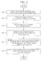
- Fig. 2 is a flowchart illustrating the method of detecting the map matching position according to the present invention.
- the control unit 110 receives navigation messages received by the GPS receiver 104 and detection signals of the sensor unit 106 (step 200), and detects coordinates P 0 of a current vehicle location using the received navigation messages and detection signals of the sensor unit 106 (step 202).
- the control unit 110 searches the map data stored in the map data storage unit 108 to find a link closest to the detected coordinates P 0 of the current vehicle location (step 204), and searches for and stores coordinates P 1 and P 2 of both end points of the searched link (step 206).
- the control unit 110 checks the orientation of a line P 1 P 2 defined by the coordinates P 1 and P 2 of the both end points of the detected link (road) (step 208), and obtains coordinates P of an intersection point of a perpendicular line drawn from the detected coordinates P 0 of the current vehicle location to line P 1 P 2 using a formula for obtaining the coordinates P of the intersection point, determines the obtained coordinates P of the intersection point of the perpendicular line as correct coordinates of the current vehicle location and performs matching (step 210).
- the orientation of line P 1 P 2 may correspond to one of a vertical case, a horizontal case, and cases other than the vertical and horizontal cases.
- the obtainment of the coordinates P of the intersection point of the perpendicular line will be described according to the orientation of line P 1 P 2 .
- one of the coefficients of the line equation can be fixed to a specific value.
- coordinates of a current vehicle location is found on a map
- a perpendicular line is drawn from the coordinates of the current vehicle location to a link closest thereto by using a general line equation
- coordinates of an intersection point of the perpendicular line are found, and the current vehicle location is matched to the coordinates of an intersection point, thereby matching the current vehicle location to a correct position on the link. Accordingly, it is possible to more correctly inform a user of the current vehicle location and to guide the travel of the vehicle by more correctly searching for a travel path of the vehicle.
Landscapes
- Engineering & Computer Science (AREA)
- Radar, Positioning & Navigation (AREA)
- Remote Sensing (AREA)
- Physics & Mathematics (AREA)
- General Physics & Mathematics (AREA)
- Automation & Control Theory (AREA)
- Navigation (AREA)
Abstract
Description
- The present invention relates to a navigation system, and more particularly, to a method for detecting a map matching position of a vehicle in a navigation system, which detects coordinates on a link (road) of map data that will be matched to coordinates of a current vehicle location obtained from navigation messages received by a GPS (global positioning system) receiver and from detection signals of a variety of sensors installed at a vehicle to detect a travel state of the vehicle.
- More specifically, the present invention relates to a method for detecting a map matching position of a vehicle in a navigation system, wherein coordinates of a current vehicle location are obtained from navigation messages received by a GPS receiver and from signals of sensors installed at a vehicle, using a general line equation for obtaining an intersection point between an arbitrary line and a perpendicular line drawn from an arbitrary point to the line, and the current vehicle location is matched to coordinates found through orthogonal projection on a link on map data closest to the obtained coordinates of the current vehicle location.
- Generally, a navigation system obtains coordinates of a current vehicle location using navigation messages transmitted by a plurality of GPS satellites arranged on geostationary orbits over the Earth and using detection signals of a plurality of sensors installed at a vehicle, including a gyro sensor for detecting a travel direction of the vehicle and a speed sensor for detecting a travel speed, matches the obtained coordinates of the current vehicle location to map data, searches for a travel path from the matched coordinates of the current vehicle location to coordinates of a destination of the vehicle through the map data, and guides the travel of the vehicle to the destination along the searched travel path.
- In such a navigation system, the coordinates of the current vehicle location obtained from the navigation messages received by the GPS receiver and the detection signals of the sensors should be exactly matched to a link on the map data in order to correctly detect the coordinates of the current vehicle location, inform a user of the detected coordinates, correctly search for the travel path from the coordinates of the current vehicle location to the coordinates of the destination, and guide the vehicle along the searched travel path.
- A conventional technique for matching coordinates of a current vehicle location to coordinates of a link on map data is disclosed in Korean Patent Application No. 1997-78443 (Laid-Open Publication No. 1999-58343). According to the conventional technique, coordinates of a current vehicle location is detected and it is determined whether the detected coordinates of the current vehicle location fall within an interpolation range of a link on map data. If it is determined that the detected coordinates of the current vehicle location fall within the interpolation range of the link on the map data, a distance between coordinates of interpolated points positioned in the interpolation range and the coordinates of the current vehicle location is calculated. The coordinates of an interpolated point in which the calculated distance is smallest are selected as coordinates of a target interpolation point. Then, the coordinates of the current vehicle location are substituted with and matched to the coordinates of the selected target interpolation point. In such a manner, a travel path of the vehicle is tracked.
- However, since the conventional technique substitutes the coordinates of the current vehicle location with the coordinates of the interpolated point on a link without searching for correct coordinates on the link of the map data to be matched to the coordinates of the current vehicle location, there is a problem in that it is not possible to correctly search for coordinates of an interpolated point to be matched to the coordinates of the current vehicle location if the coordinates of the current vehicle location exist between coordinates of two adjacent interpolated points.
- An object of the present invention is to provide a method for detecting a map matching position of a vehicle in a navigation system, wherein coordinates of a point existing on a link of map data, which are closest to coordinates of a current vehicle location, are calculated using a general line equation for obtaining an intersection point between an arbitrary line and a perpendicular line drawn from an arbitrary point to the line.
- According to an aspect of the present invention for achieving the object, there is provided a method for detecting a map matching position of a vehicle in a navigation system, comprising the steps of (a) obtaining coordinates P0 of a current vehicle location; (b) searching map data to find one link to which the coordinates P0 of the current vehicle location obtained in step (a) will be matched; (c) drawing a perpendicular line from the coordinates P0 of the current vehicle location obtained in step (a) to the link found in step (b) and obtaining coordinates P of an intersection point of the perpendicular line; and (d) determining the coordinates of the current vehicle location to be the coordinates P of the intersection point obtained in step (c).
- The coordinates P0 of the current vehicle location obtained in step (a) may be coordinates of a location detected using navigation messages received by a GPS receiver and detection signals of sensors installed on the vehicle. The link found in step (b) may be a link on the map data closest to the coordinates P0 of the current vehicle location.
- According to another aspect of the present invention, there is provide a method for detecting a map matching position of a vehicle in a navigation system, comprising the steps of (a) obtaining, by a control unit, coordinates P0 of a current vehicle location using navigation messages received by a GPS receiver and detection signals of sensors installed on the vehicle; (b) searching map data to find one link to which the coordinates P0 of the current vehicle location obtained in step (a) will be matched, and obtaining coordinates P1 and P2 of both end points of the link; (c) obtaining coordinates P of an intersection point of a perpendicular linedrawn from the coordinates P0 of the current vehicle location obtained in step (a) to a line
 defined by the coordinates P1 and P2 of the both end points of the link obtained in step (b); and (d) determining the coordinates of the current vehicle location to be the coordinates P of the intersection point obtained in step (c).
- The link found in step (b) may be a link on the map data closest to the coordinates P0 of the current vehicle location.
- Step (c) may further comprise the steps of determining an orientation of the linedefined by the coordinates P1 and P2 of the both end points of the link obtained in step (b); and obtaining the coordinates P of the intersection point of the perpendicular line according to the determined orientation. If the orientation of the line

P1P2 is not vertical or horizontal on a digital map, the coordinates P of the intersection point of the perpendicular line may be calculated from the following formula:If the orientation of the line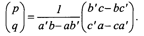 is vertical on a digital map, the coordinates P of the intersection point of the perpendicular line may be determined to be (x1, y0). If the orientation of the line
P1P2 is horizontal on a digital map, the coordinates P of the intersection point of the perpendicular line may be determined to be (x0, y1). - Here, p and q are x- and y-axis coordinate values of the coordinates P of the intersection point of the perpendicular line, respectively, and a, b, c, a', b' and c' are coefficients of an equation for line, ax+ by+ c = 0, and an equation for line
 , a'x+ b' y+ c'= 0 . x1 is x-axis coordinate values of the coordinates P1 and P2, and y0 is a y-axis coordinate value of the coordinates P0. x0 is an x-axis coordinate value of the coordinates Po, and y1 is y-axis coordinate values of the coordinates P1 and P2.
- The above and other objects, features and advantages of the present invention will become apparent from the following description of a preferred embodiment given in conjunction with the accompanying drawings, in which:
- Fig. 1 is a block diagram showing a configuration of a navigation system to which a method of detecting a map matching position according to the present invention is applied;
- Fig. 2 is a flowchart illustrating the method of detecting the map matching position according to the present invention; and
- Figs. 3 to 5 are views illustrating operations for obtaining an intersection point of a perpendicular line in the method of detecting the map matching position according to the present invention.
-
- Hereinafter, a method of detecting a map matching position of a vehicle in a navigation system according to the present invention will be described in detail with reference to accompanying drawings.
- Fig. 1 is a block diagram showing a configuration of a navigation system to which the method of detecting the map matching position according to the present invention is applied. As shown in the figure, the navigation system comprises a
GPS receiver 104 for receiving navigation messages, which have been transmitted by a plurality ofGPS satellites 100, through anantenna 102; asensor unit 106 installed at a vehicle to detect a travel direction, a travel speed and the like of a vehicle; a mapdata storage unit 108 for storing map data in a storage medium such as a compact disk or a memory; acontrol unit 110 capable of controlling operations for detecting coordinates of a current vehicle location from the navigation messages received by theGPS receiver 104 and detection signals of thesensor unit 106, for matching the detected coordinates of the current vehicle location to a link on map data stored in the mapdata storage unit 108 and for searching a travel path from the matched position to coordinates of a destination of the vehicle so as to guide the travel of the vehicle; adisplay driving unit 112 for causing the current vehicle location together with a map to be displayed on adisplay unit 114 under the control of thecontrol unit 110; and avoice guidance unit 116 for guiding the travel of the vehicle using voices through aspeaker 118 under the control of thecontrol unit 110. - When the vehicle travels, the
GPS receiver 102 of the navigation system constructed as above receives the navigation messages transmitted by the plurality ofGPS satellites 100 and inputs them into thecontrol unit 110, and thesensor unit 106 detects a travel state, including a travel direction and a travel speed of the vehicle, and inputs it into thecontrol unit 110. - Then, the
control unit 110 detects the coordinates of the current vehicle location using the navigation messages received by theGPS receiver 102 and the detection signals of thesensor unit 106, matches the detected coordinates of the current vehicle location to a link on the map data stored in the mapdata storage unit 108, and outputs the matched results to thedisplay unit 114 through thedisplay driving unit 112 to display the map and the current vehicle location. - When a user of the vehicle sets coordinates of a destination to which the vehicle will travel, the
control unit 110 searches the map data to find a travel path to the coordinates of the destination from the coordinates of the link on the map data to which the current vehicle location has been matched, and causes the searched travel path together with a map to be displayed on thedisplay unit 114 through thedisplay driving unit 112 and guidance voices to be simultaneously output from thespeaker 118 through thevoice guidance unit 116, thereby guiding the vehicle along the travel path. - Fig. 2 is a flowchart illustrating the method of detecting the map matching position according to the present invention. As shown in the figure, the
control unit 110 receives navigation messages received by theGPS receiver 104 and detection signals of the sensor unit 106 (step 200), and detects coordinates P0 of a current vehicle location using the received navigation messages and detection signals of the sensor unit 106 (step 202). - The
control unit 110 searches the map data stored in the mapdata storage unit 108 to find a link closest to the detected coordinates P0 of the current vehicle location (step 204), and searches for and stores coordinates P1 and P2 of both end points of the searched link (step 206). - The
control unit 110 checks the orientation of a lineP1P2 defined by the coordinates P1 and P2 of the both end points of the detected link (road) (step 208), and obtains coordinates P of an intersection point of a perpendicular line drawn from the detected coordinates P0 of the current vehicle location to lineP1P2 using a formula for obtaining the coordinates P of the intersection point, determines the obtained coordinates P of the intersection point of the perpendicular line as correct coordinates of the current vehicle location and performs matching (step 210). - Next, the operation for obtaining the coordinates P of the intersection point of the perpendicular line drawn from the coordinates P0 of the current vehicle location to line
P1P2 will be described in detail with reference to Figs. 3 to 5. - A line equation of which a gradient is m and a y-intercept is n is expressed as the flowing formula 1:
- In the line equation expressed as formula 1, a line parallel with the y-axis cannot be expressed since the value of the gradient m approaches infinite as the orientation of a line becomes closer to a vertical line.
- Therefore, the line equation expressed as formula 1 cannot be used for obtaining the coordinates P of the intersection point of the perpendicular line drawn from the coordinates P0 of the current vehicle location to line. Accordingly, a general line equation expressed as the following formula 2 should be used:

- If b=0 in formula 2, a line parallel with the y-axis can be expressed as a line equation. Thus, it can be understood that formula 2 is more general than formula 1 expressed using the gradient and the y-intercept.
- To obtain an intersection point of a perpendicular line, line equations for lines
P1P2 andP0P are defined herein as the following formulas 3 and 4:

- The orientation of line
P1P2 may correspond to one of a vertical case, a horizontal case, and cases other than the vertical and horizontal cases. The obtainment of the coordinates P of the intersection point of the perpendicular line will be described according to the orientation of lineP1P2 . - In the equation for line, x-axis coordinate values x1 and x2 of P1 and P2 are identical with each other (xi=x2). In the equation for line
 , y=y0. Therefore, the coordinates P of the intersection point of the perpendicular line for connecting the two lines
 and
and are (x1, y0).
- In the equation for line
P1P2 , y-axis coordinate values y1 and y2 of P1 and P2 are identical with each other (y1=y2). In the equation for lineP0P , x=x0. Therefore, the coordinates P of the intersection point of the perpendicular line for connecting the two linesand are (x0, y1).
- Assuming that the coordinates P of the intersection point of the perpendicular line for connecting the two linesand
 are (p, q), the following formula 5 is established:
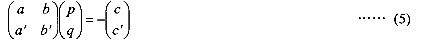
- The coordinates P of the intersection point of the perpendicular line, i.e. (p, q), are obtained by arranging formula 5 as expressed in the following formula 6:

- Here, since linesand
 are not parallel with each other and both of a and b are not 0, a' / a ≠ b' / b.
- Therefore, since a'b-ab'≠ 0, there exists an inverse matrix.
- Thus, it can be understood that the coordinates P of the intersection point of the perpendicular line, i.e. (p, q), are dependent on the coefficients a, b, c, a', b' and c' of the line equations.
- Generally, even when both sides of a line equation are multiplied by an arbitrary number other than 0, the equation is established as well. That is, even though the line equation for lineis multiplied by a constant k other than 0, this represents the same line equation as line

P1P2 like the following formula 7:
- Therefore, one of the coefficients of the line equation can be fixed to a specific value.
- Here, assume that b of the coefficients of the line equation for line
P1P2 is -1, and b' of the coefficients of the line equation for lineis -1, as shown in formula 8:
- Then, the following formulas 9 and 10 can be obtained for linesand
 :
:


- Since the coordinates P1(x1, y1) and P2(x2, y2) correspond to points on line, the substitution of the coordinates P1 and P2 of the two points into formula 9 results in a relational expression like the following formula 11:


- When formula 11 is arranged and the coefficients a and c are calculated, the following formula 12 is obtained:

- Here, since lineis not parallel with the y-axis, x1-x2 ≠ 0 and there exists an inverse matrix.

- Since the two linesand
 are perpendicular to each other, the coefficient a' can be obtained from the following equation 13:
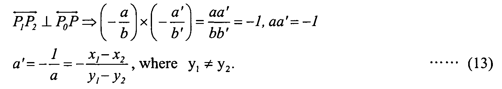
- Here, since lineis not parallel with the x-axis, y1- y2 ≠ 0.

- Meanwhile, since the coordinates P0 correspond to a point existing on line, the following formula 14 can be obtained by substituting the coordinates P0, i.e. (x0, y0), into formula 10 which in turn will be arranged:

- When the values of the coefficients obtained as such are substituted into formula 6, it is possible to obtain the coordinates P of the intersection point of the perpendicular line drawn from the coordinates P0 of the current vehicle location to line.

- As described above, according to the present invention, coordinates of a current vehicle location is found on a map, a perpendicular line is drawn from the coordinates of the current vehicle location to a link closest thereto by using a general line equation, coordinates of an intersection point of the perpendicular line are found, and the current vehicle location is matched to the coordinates of an intersection point, thereby matching the current vehicle location to a correct position on the link. Accordingly, it is possible to more correctly inform a user of the current vehicle location and to guide the travel of the vehicle by more correctly searching for a travel path of the vehicle.
- Although the present invention has been illustrated and described in connection with the preferred embodiment, it will be readily understood by those skilled in the art that various adaptations and changes can be made thereto without departing from the spirit and scope of the present invention defined by the appended claims.
Claims (9)
- A method for detecting a map matching position of a vehicle in a navigation system, comprising the steps of:(a) obtaining coordinates (Po) of a current vehicle location;(b) searching map data to find one link to which the coordinates (P0) of the current vehicle location obtained in step (a) will be matched;(c) drawing a perpendicular line from the coordinates (P0) of the current vehicle location obtained in step (a) to the link found in step (b) and obtaining coordinates (P) of an intersection point of the perpendicular line; and(d) determining the coordinates of the current vehicle location to be the coordinates (P) of the intersection point obtained in step (c).
- The method as claimed in claim 1, wherein the coordinates (P0) of the current vehicle location obtained in step (a) are coordinates of a location detected using navigation messages received by a GPS receiver and detection signals of sensors installed on the vehicle.
- The method as claimed in claim 1, wherein the link found in step (b) is a link on the map data closest to the coordinates (P0) of the current vehicle location.
- A method for detecting a map matching position of a vehicle in a navigation system, comprising the steps of:(a) obtaining, by a control unit, coordinates (P0) of a current vehicle location using navigation messages received by a GPS receiver and detection signals of sensors installed on the vehicle;(b) searching map data to find one link to which the coordinates (P0) of the current vehicle location obtained in step (a) will be matched, and obtaining coordinates (P1, P2) of both end points of the link;(c) obtaining coordinates (P) of an intersection point of a perpendicular line () drawn from the coordinates (P0) of the current vehicle location obtained in step (a) to a line (

P1P2 ) defined by the coordinates (P1, P2) of the both end points of the link obtained in step (b); and(d) determining the coordinates of the current vehicle location to be the coordinates (P) of the intersection point obtained in step (c). - The method as claimed in claim 4, wherein the link found in step (b) is a link on the map data closest to the coordinates (P0) of the current vehicle location.
- The method as claimed in claim 5, wherein step (c) further comprises the steps of:determining an orientation of the line (
P1P2 ) defined by the coordinates (P1, P2) of the both end points of the link obtained in step (b); andobtaining the coordinates (P) of the intersection point of the perpendicular line according to the determined orientation. - The method as claimed in claim 6, wherein if the orientation of the line () is not vertical or horizontal on a digital map, the coordinates (P) of the intersection point of the perpendicular line are calculated from the following formula:
 where p and q are x- and y-axis coordinate values of the coordinates (P) of the intersection point of the perpendicular line, respectively, and a, b, c, a', b' and c' are coefficients of an equation for line (
 ), ax+ by+ c = 0 , and an equation for line (
 ), a'x+ b' y+ c'= 0 .
- The method as claimed in claim 6, wherein if the orientation of the line () is vertical on a digital map, the coordinates (P) of the intersection point of the perpendicular line is determined to be (x1, y0), where x1 is x-axis coordinate values of the coordinates (P1, P2), and y0 is a y-axis coordinate value of the coordinates (P0).

- The method as claimed in claim 6, wherein if the orientation of the line () is horizontal on a digital map, the coordinates (P) of the intersection point of the perpendicular line is determined to be (x0, y1), where x0 is an x-axis coordinate value of the coordinates (P0), and y1 is y-axis coordinate values of the coordinates (P1, P2).

Applications Claiming Priority (2)
| Application Number | Priority Date | Filing Date | Title |
|---|---|---|---|
| KR2003072906 | 2003-10-20 | ||
| KR10-2003-0072906A KR100520709B1 (en) | 2003-10-20 | 2003-10-20 | Method for detecting map matching position of vehicle in navigation system |
Publications (1)
| Publication Number | Publication Date |
|---|---|
| EP1526357A1 true EP1526357A1 (en) | 2005-04-27 |
Family
ID=34386780
Family Applications (1)
| Application Number | Title | Priority Date | Filing Date |
|---|---|---|---|
| EP04292372A Withdrawn EP1526357A1 (en) | 2003-10-20 | 2004-10-06 | Method for detecting map matching position of vehicle in navigation system |
Country Status (4)
| Country | Link |
|---|---|
| US (1) | US7197392B2 (en) |
| EP (1) | EP1526357A1 (en) |
| KR (1) | KR100520709B1 (en) |
| CN (1) | CN1312642C (en) |
Cited By (1)
| Publication number | Priority date | Publication date | Assignee | Title |
|---|---|---|---|---|
| EP2101148A1 (en) | 2008-03-11 | 2009-09-16 | GMV Aerospace and Defence S.A. | Method for map matching with guaranteed integrity |
Families Citing this family (13)
| Publication number | Priority date | Publication date | Assignee | Title |
|---|---|---|---|---|
| JP4680131B2 (en) * | 2006-05-29 | 2011-05-11 | トヨタ自動車株式会社 | Own vehicle position measuring device |
| US20070288164A1 (en) * | 2006-06-08 | 2007-12-13 | Microsoft Corporation | Interactive map application |
| TWI284193B (en) * | 2006-07-06 | 2007-07-21 | Sin Etke Technology Co Ltd | A display correction of vehicle navigation system and the correction and display method thereof |
| KR100753545B1 (en) * | 2006-12-27 | 2007-08-30 | (주)씨랩시스 | Navigation device having a GPS data processing function and a method for processing the GPS signal in the navigation device |
| US20100057358A1 (en) * | 2008-08-28 | 2010-03-04 | TeleType Co., Inc. | Portable gps map device for commercial vehicle industry |
| US8086364B2 (en) * | 2009-03-11 | 2011-12-27 | General Electric Company | System and method for operation of electric and hybrid vehicles |
| US20110130962A1 (en) * | 2009-12-02 | 2011-06-02 | Larry Damell Lindsey | Navigation system for delivery vehicles |
| US8442763B2 (en) * | 2010-04-16 | 2013-05-14 | CSR Technology Holdings Inc. | Method and apparatus for geographically aiding navigation satellite system solution |
| WO2014143058A1 (en) * | 2013-03-15 | 2014-09-18 | Hewlett-Packard Development Company, L.P. | Map matching |
| GB201321357D0 (en) * | 2013-12-04 | 2014-01-15 | Tomtom Int Bv | A method of resolving a point location from encoded data representative thereof |
| US10332395B1 (en) | 2017-12-21 | 2019-06-25 | Denso International America, Inc. | System and method for translating roadside device position data according to differential position data |
| EP3865822B1 (en) * | 2018-05-15 | 2024-10-02 | Mobileye Vision Technologies Ltd. | Systems and methods for autonomous vehicle navigation |
| CN110489510B (en) * | 2019-08-23 | 2022-05-20 | 腾讯科技(深圳)有限公司 | Road data processing method and device, readable storage medium and computer equipment |
Citations (6)
| Publication number | Priority date | Publication date | Assignee | Title |
|---|---|---|---|---|
| EP0339639A2 (en) * | 1988-04-28 | 1989-11-02 | Mazda Motor Corporation | Apparatus for navigating vehicle |
| KR19990058343A (en) | 1997-12-30 | 1999-07-15 | 오상수 | Map Matching Method of Vehicle Navigation System and Its Apparatus |
| US6335695B1 (en) * | 1999-07-21 | 2002-01-01 | Denso Corporation | Map display apparatus |
| US20020072849A1 (en) * | 1995-12-28 | 2002-06-13 | Alpine Electronics Inc. | Vehicle navigation apparatus providing proper guidance for off-road net conditions |
| EP1233251A2 (en) | 2001-02-14 | 2002-08-21 | Matsushita Electric Industrial Co., Ltd. | Navigation system |
| US20020177950A1 (en) | 2001-05-24 | 2002-11-28 | Davies F. Bryan | Satellite based on-board vehicle navigation system including predictive filtering and map-matching to reduce errors in a vehicular position |
Family Cites Families (5)
| Publication number | Priority date | Publication date | Assignee | Title |
|---|---|---|---|---|
| JP2783922B2 (en) * | 1991-09-02 | 1998-08-06 | アルパイン株式会社 | Vehicle position correction method |
| JP2826079B2 (en) * | 1995-04-21 | 1998-11-18 | 株式会社ザナヴィ・インフォマティクス | In-vehicle map database device |
| US5919245A (en) * | 1995-04-21 | 1999-07-06 | Xanavi Informatics Corporation | Map database apparatus |
| JP3143927B2 (en) * | 1996-09-20 | 2001-03-07 | トヨタ自動車株式会社 | Position information providing system and device |
| US6581005B2 (en) * | 2000-11-30 | 2003-06-17 | Nissan Motor Co., Ltd. | Vehicle position calculation apparatus and method |
-
2003
- 2003-10-20 KR KR10-2003-0072906A patent/KR100520709B1/en not_active Expired - Fee Related
-
2004
- 2004-10-06 EP EP04292372A patent/EP1526357A1/en not_active Withdrawn
- 2004-10-12 US US10/964,028 patent/US7197392B2/en not_active Expired - Fee Related
- 2004-10-20 CN CNB2004100864147A patent/CN1312642C/en not_active Expired - Fee Related
Patent Citations (6)
| Publication number | Priority date | Publication date | Assignee | Title |
|---|---|---|---|---|
| EP0339639A2 (en) * | 1988-04-28 | 1989-11-02 | Mazda Motor Corporation | Apparatus for navigating vehicle |
| US20020072849A1 (en) * | 1995-12-28 | 2002-06-13 | Alpine Electronics Inc. | Vehicle navigation apparatus providing proper guidance for off-road net conditions |
| KR19990058343A (en) | 1997-12-30 | 1999-07-15 | 오상수 | Map Matching Method of Vehicle Navigation System and Its Apparatus |
| US6335695B1 (en) * | 1999-07-21 | 2002-01-01 | Denso Corporation | Map display apparatus |
| EP1233251A2 (en) | 2001-02-14 | 2002-08-21 | Matsushita Electric Industrial Co., Ltd. | Navigation system |
| US20020177950A1 (en) | 2001-05-24 | 2002-11-28 | Davies F. Bryan | Satellite based on-board vehicle navigation system including predictive filtering and map-matching to reduce errors in a vehicular position |
Cited By (2)
| Publication number | Priority date | Publication date | Assignee | Title |
|---|---|---|---|---|
| EP2101148A1 (en) | 2008-03-11 | 2009-09-16 | GMV Aerospace and Defence S.A. | Method for map matching with guaranteed integrity |
| US8032299B2 (en) | 2008-03-11 | 2011-10-04 | Gmv Aerospace And Defence S.A. | Method for map matching with guaranteed integrity |
Also Published As
| Publication number | Publication date |
|---|---|
| CN1609912A (en) | 2005-04-27 |
| US7197392B2 (en) | 2007-03-27 |
| KR100520709B1 (en) | 2005-10-17 |
| KR20050037670A (en) | 2005-04-25 |
| CN1312642C (en) | 2007-04-25 |
| US20050085995A1 (en) | 2005-04-21 |
Similar Documents
| Publication | Publication Date | Title |
|---|---|---|
| US8055442B2 (en) | Determining a display position of road name data and displaying the road name data | |
| KR100696801B1 (en) | Navigation system and its location search method | |
| EP1526357A1 (en) | Method for detecting map matching position of vehicle in navigation system | |
| EP1557642A2 (en) | Method for converting coordinate values of map data | |
| US20070233373A1 (en) | Map scale changing method and apparatus for navigation system | |
| US7266448B2 (en) | Method for searching return path of moving object for use in navigation system | |
| US20200210725A1 (en) | Image collection system, image collection method, image collection device, recording medium, and vehicle communication device | |
| EP1655578B1 (en) | Voice guidance method of travel route in navigation system | |
| US20060100778A1 (en) | Navigation device and method using multi-route | |
| JP7456714B2 (en) | In-vehicle system | |
| US8214149B2 (en) | Navigation apparatus and positioning method thereof | |
| KR20060118234A (en) | Summary route guidance method of navigation system | |
| US6816781B2 (en) | Navigation method and system for large compound | |
| JP2002310690A (en) | Position precision improving method for navigation system | |
| CN100470199C (en) | Walking navigation device and method | |
| CN100397437C (en) | Navigation system and control method for a motor vehicle | |
| JP5597080B2 (en) | Computer program, map display device, and method for map data to be processed by map display device | |
| JP4455155B2 (en) | Mobile navigation device | |
| US9689689B2 (en) | Navigation device and program for performing route guidance along a route using, as a recognized road, an extension road not actually traveled which extends straight from and is continuous with a road actually traveled | |
| US12601606B2 (en) | Audio output device, audio output method, program and storage medium | |
| KR20030009944A (en) | Navigation system and method for providing position data using telephone number | |
| JP2003344065A (en) | On-vehicle navigation apparatus, navigation method, and program | |
| KR100452776B1 (en) | The vehicle information guidance terminal using Global Positioning System | |
| JP3401981B2 (en) | Navigation device | |
| KR100510944B1 (en) | A Method for guiding return routes of vehicles in navigation systems |
Legal Events
| Date | Code | Title | Description |
|---|---|---|---|
| PUAI | Public reference made under article 153(3) epc to a published international application that has entered the european phase |
Free format text: ORIGINAL CODE: 0009012 |
|
| 17P | Request for examination filed |
Effective date: 20041013 |
|
| AK | Designated contracting states |
Kind code of ref document: A1 Designated state(s): AT BE BG CH CY CZ DE DK EE ES FI FR GB GR HU IE IT LI LU MC NL PL PT RO SE SI SK TR |
|
| AX | Request for extension of the european patent |
Extension state: AL HR LT LV MK |
|
| AKX | Designation fees paid |
Designated state(s): DE FR GB NL |
|
| 17Q | First examination report despatched |
Effective date: 20110728 |
|
| STAA | Information on the status of an ep patent application or granted ep patent |
Free format text: STATUS: THE APPLICATION IS DEEMED TO BE WITHDRAWN |
|
| 18D | Application deemed to be withdrawn |
Effective date: 20121206 |