EP1526348A1 - Built-in refrigerator - Google Patents
Built-in refrigerator Download PDFInfo
- Publication number
- EP1526348A1 EP1526348A1 EP03023820A EP03023820A EP1526348A1 EP 1526348 A1 EP1526348 A1 EP 1526348A1 EP 03023820 A EP03023820 A EP 03023820A EP 03023820 A EP03023820 A EP 03023820A EP 1526348 A1 EP1526348 A1 EP 1526348A1
- Authority
- EP
- European Patent Office
- Prior art keywords
- condenser
- compressor
- base portion
- refrigerator
- wall
- Prior art date
- Legal status (The legal status is an assumption and is not a legal conclusion. Google has not performed a legal analysis and makes no representation as to the accuracy of the status listed.)
- Withdrawn
Links
- 238000011144 upstream manufacturing Methods 0.000 claims abstract description 3
- 238000001816 cooling Methods 0.000 claims description 8
- 238000005192 partition Methods 0.000 claims description 7
- 238000007789 sealing Methods 0.000 claims description 6
- 239000000463 material Substances 0.000 claims description 2
- 238000009434 installation Methods 0.000 description 3
- 230000006978 adaptation Effects 0.000 description 2
- 238000005265 energy consumption Methods 0.000 description 2
- 239000000853 adhesive Substances 0.000 description 1
- 230000001070 adhesive effect Effects 0.000 description 1
- 230000000694 effects Effects 0.000 description 1
- 238000005057 refrigeration Methods 0.000 description 1
Images


Classifications
-
- F—MECHANICAL ENGINEERING; LIGHTING; HEATING; WEAPONS; BLASTING
- F25—REFRIGERATION OR COOLING; COMBINED HEATING AND REFRIGERATION SYSTEMS; HEAT PUMP SYSTEMS; MANUFACTURE OR STORAGE OF ICE; LIQUEFACTION SOLIDIFICATION OF GASES
- F25D—REFRIGERATORS; COLD ROOMS; ICE-BOXES; COOLING OR FREEZING APPARATUS NOT OTHERWISE PROVIDED FOR
- F25D23/00—General constructional features
- F25D23/003—General constructional features for cooling refrigerating machinery
-
- F—MECHANICAL ENGINEERING; LIGHTING; HEATING; WEAPONS; BLASTING
- F25—REFRIGERATION OR COOLING; COMBINED HEATING AND REFRIGERATION SYSTEMS; HEAT PUMP SYSTEMS; MANUFACTURE OR STORAGE OF ICE; LIQUEFACTION SOLIDIFICATION OF GASES
- F25D—REFRIGERATORS; COLD ROOMS; ICE-BOXES; COOLING OR FREEZING APPARATUS NOT OTHERWISE PROVIDED FOR
- F25D23/00—General constructional features
- F25D23/10—Arrangements for mounting in particular locations, e.g. for built-in type, for corner type
-
- F—MECHANICAL ENGINEERING; LIGHTING; HEATING; WEAPONS; BLASTING
- F25—REFRIGERATION OR COOLING; COMBINED HEATING AND REFRIGERATION SYSTEMS; HEAT PUMP SYSTEMS; MANUFACTURE OR STORAGE OF ICE; LIQUEFACTION SOLIDIFICATION OF GASES
- F25D—REFRIGERATORS; COLD ROOMS; ICE-BOXES; COOLING OR FREEZING APPARATUS NOT OTHERWISE PROVIDED FOR
- F25D2323/00—General constructional features not provided for in other groups of this subclass
- F25D2323/002—Details for cooling refrigerating machinery
- F25D2323/0026—Details for cooling refrigerating machinery characterised by the incoming air flow
- F25D2323/00261—Details for cooling refrigerating machinery characterised by the incoming air flow through the back bottom side
-
- F—MECHANICAL ENGINEERING; LIGHTING; HEATING; WEAPONS; BLASTING
- F25—REFRIGERATION OR COOLING; COMBINED HEATING AND REFRIGERATION SYSTEMS; HEAT PUMP SYSTEMS; MANUFACTURE OR STORAGE OF ICE; LIQUEFACTION SOLIDIFICATION OF GASES
- F25D—REFRIGERATORS; COLD ROOMS; ICE-BOXES; COOLING OR FREEZING APPARATUS NOT OTHERWISE PROVIDED FOR
- F25D2323/00—General constructional features not provided for in other groups of this subclass
- F25D2323/002—Details for cooling refrigerating machinery
- F25D2323/0026—Details for cooling refrigerating machinery characterised by the incoming air flow
- F25D2323/00264—Details for cooling refrigerating machinery characterised by the incoming air flow through the front bottom part
-
- F—MECHANICAL ENGINEERING; LIGHTING; HEATING; WEAPONS; BLASTING
- F25—REFRIGERATION OR COOLING; COMBINED HEATING AND REFRIGERATION SYSTEMS; HEAT PUMP SYSTEMS; MANUFACTURE OR STORAGE OF ICE; LIQUEFACTION SOLIDIFICATION OF GASES
- F25D—REFRIGERATORS; COLD ROOMS; ICE-BOXES; COOLING OR FREEZING APPARATUS NOT OTHERWISE PROVIDED FOR
- F25D2323/00—General constructional features not provided for in other groups of this subclass
- F25D2323/002—Details for cooling refrigerating machinery
- F25D2323/0026—Details for cooling refrigerating machinery characterised by the incoming air flow
- F25D2323/00266—Details for cooling refrigerating machinery characterised by the incoming air flow through the bottom
-
- F—MECHANICAL ENGINEERING; LIGHTING; HEATING; WEAPONS; BLASTING
- F25—REFRIGERATION OR COOLING; COMBINED HEATING AND REFRIGERATION SYSTEMS; HEAT PUMP SYSTEMS; MANUFACTURE OR STORAGE OF ICE; LIQUEFACTION SOLIDIFICATION OF GASES
- F25D—REFRIGERATORS; COLD ROOMS; ICE-BOXES; COOLING OR FREEZING APPARATUS NOT OTHERWISE PROVIDED FOR
- F25D2323/00—General constructional features not provided for in other groups of this subclass
- F25D2323/002—Details for cooling refrigerating machinery
- F25D2323/0027—Details for cooling refrigerating machinery characterised by the out-flowing air
- F25D2323/00271—Details for cooling refrigerating machinery characterised by the out-flowing air from the back bottom
-
- F—MECHANICAL ENGINEERING; LIGHTING; HEATING; WEAPONS; BLASTING
- F25—REFRIGERATION OR COOLING; COMBINED HEATING AND REFRIGERATION SYSTEMS; HEAT PUMP SYSTEMS; MANUFACTURE OR STORAGE OF ICE; LIQUEFACTION SOLIDIFICATION OF GASES
- F25D—REFRIGERATORS; COLD ROOMS; ICE-BOXES; COOLING OR FREEZING APPARATUS NOT OTHERWISE PROVIDED FOR
- F25D2323/00—General constructional features not provided for in other groups of this subclass
- F25D2323/002—Details for cooling refrigerating machinery
- F25D2323/0027—Details for cooling refrigerating machinery characterised by the out-flowing air
- F25D2323/00272—Details for cooling refrigerating machinery characterised by the out-flowing air from the back top
Definitions
- the present invention relates to a household refrigerator of the built-in type, comprising a refrigerated compartment and a basement containing a condenser, a fan and a compressor, said basement having an open rear face facing a house wall where the refrigerator is adapted to be installed.
- household refrigerator as used in this description and the appended claims is intended to include refrigerators and freezers.
- Refrigerators of the above type have the advantage of maximising the volume of the appliance since the condenser is placed in the basement and not between the wall and the rear face of the refrigerator.
- the condenser and the fan are placed in a bottom niche together with the compressor.
- the fan creates an airflow directed towards the front wall of the refrigerator or towards an interspace between the house wall and the rear wall of the refrigerators.
- a sort of "short-circuit" between cold and warm air is avoided, and cooling air is forced in a sort of "chimney” defined by the above interspace so that also a convection effect is added to the forced air flow.
- the drawback of this solution is that the furniture containing the built-in refrigerator may need some adaptation work in order to create a proper cooling airflow pattern.
- Such usual adaptation is needed especially in certain countries where the wooden door of the kitchen furniture abuts the front edge of the furniture cavity containing the built-in refrigerator.
- the cooling air has to flow under the furniture (i.e. between the floor and the furniture) and cannot be sucked by the fan which therefore is substantially useless.
- the installation of the refrigerator is not properly made (i.e. the aperture in the furniture is not cut before the installation) the refrigerator will work with a condenser at a much higher temperature than designed, with problems of higher energy demand and possibility of compressor failures.
- Purpose of the present invention is to provide a household refrigerator of the built-in type in which there is no need of adapting the furniture in order to have a proper flow of cooling air.
- Another purpose of the present invention is to provide a built-in refrigerator in which the cooling of the condenser and compressor is improved, so that energy saving is obtained too.
- a refrigerator in which the rear face of the basement is provided with sealing means adapted to cooperate with the house wall in order to define an air suction mouth upstream the condenser.
- a partition wall is preferably provided between the condenser and the compressor so as to define a U-shaped channel or duct and in order to cool the compressor downstream the condenser.
- FIG 1 With reference to figure 1, with 10 is indicated a built-in refrigerator installed in a standard cavity C defined by a rear house wall W and side furniture walls P (figure 3).
- the built-in refrigerator 10 has an upper refrigeration compartment 10a and a lower freezer compartment 10b.
- a space K is defined between the refrigerator and a bottom wall B of the furniture.
- the wooden door D of the furniture closes the space K, and therefore the air can flow only under the bottom wall B of the furniture for reaching the fan 12.
- the fan 12, a condenser 14 and a compressor 16 are contained in a niche 18 defined in the basement of the refrigerator 10.
- the niche 18 has an open rear portion 18a facing the wall W where the refrigerator is installed.
- a partition wall 20 whose function is to create an U-shaped air flow around the partition 20.
- the air taken from the external ambient is forced to pass through the condenser 14 and the compressor 16, as there is still a potential for heat transfer with the compressor, since it is at a higher temperature.
- a preferable path with a low pressure drop is created for the air going out after passing through condenser 14 and compressor 16, without going back to the fan inlet region.
- the above desired flow pattern is obtained by sealing the inlet region of the fan 12. This is realised by adding to an upper edge of the rear portion 18a of the niche 18 and to the rear edge of the partition wall 20 a L-shaped rubber gasket 22 which abuts against the wall W on which the refrigerator 10 is placed.
- Other kinds of gasket can be used, for instance made by foamed polypropilene or similar foamed polymeric material.
- the use of the gasket 22 avoids air recirculation between high pressure and low pressure areas as this means a very good air flow and performance.
- the gasket 22 is fixed to a corresponding L-shaped seat 22a (figure 2) by means of adhesive or known fastening means.
- the air pushed by the fan 12 passes through the condenser 14 first, then through the compressor 16 and finally escapes from the compressor niche 18 towards a space H defined between the rear wall of the refrigerator 10 and the house wall W.
- the arrows show the main air flow pattern where air is sucked mainly from a bottom front portion 21 of the refrigerator 10 and is discharged in the interpsace H that acts like a chimney.
Landscapes
- Engineering & Computer Science (AREA)
- Chemical & Material Sciences (AREA)
- Combustion & Propulsion (AREA)
- Physics & Mathematics (AREA)
- Mechanical Engineering (AREA)
- Thermal Sciences (AREA)
- General Engineering & Computer Science (AREA)
- Devices That Are Associated With Refrigeration Equipment (AREA)
- Refrigerator Housings (AREA)
Abstract
A built-in refrigerator comprises a refrigerated compartment and a
base portion containing a condenser (14), a fan (12) and a compressor (16),
said base portion having an open rear face (18a) adapted to face a house
wall (W) where the refrigerator is adapted to be installed. The rear
face of the base portion is provided with a gasket (22) adapted to
cooperate with said house wall (W) in order to define an air suction
mouth upstream the condenser (14).
Description
- The present invention relates to a household refrigerator of the built-in type, comprising a refrigerated compartment and a basement containing a condenser, a fan and a compressor, said basement having an open rear face facing a house wall where the refrigerator is adapted to be installed.
- The term "household refrigerator" as used in this description and the appended claims is intended to include refrigerators and freezers.
- Refrigerators of the above type have the advantage of maximising the volume of the appliance since the condenser is placed in the basement and not between the wall and the rear face of the refrigerator. In order to use this space, the condenser and the fan are placed in a bottom niche together with the compressor. In such refrigerators the fan creates an airflow directed towards the front wall of the refrigerator or towards an interspace between the house wall and the rear wall of the refrigerators. In the second case a sort of "short-circuit" between cold and warm air is avoided, and cooling air is forced in a sort of "chimney" defined by the above interspace so that also a convection effect is added to the forced air flow. The drawback of this solution is that the furniture containing the built-in refrigerator may need some adaptation work in order to create a proper cooling airflow pattern. Such usual adaptation is needed especially in certain countries where the wooden door of the kitchen furniture abuts the front edge of the furniture cavity containing the built-in refrigerator. In this case, since no suction front opening is defined between the furniture and the refrigerator, without the above mentioned aperture in the bottom wall of the furniture the cooling air has to flow under the furniture (i.e. between the floor and the furniture) and cannot be sucked by the fan which therefore is substantially useless. In view of the above, if the installation of the refrigerator is not properly made (i.e. the aperture in the furniture is not cut before the installation) the refrigerator will work with a condenser at a much higher temperature than designed, with problems of higher energy demand and possibility of compressor failures.
- Purpose of the present invention is to provide a household refrigerator of the built-in type in which there is no need of adapting the furniture in order to have a proper flow of cooling air. Another purpose of the present invention is to provide a built-in refrigerator in which the cooling of the condenser and compressor is improved, so that energy saving is obtained too.
- Such purposes are achieved by a refrigerator in which the rear face of the basement is provided with sealing means adapted to cooperate with the house wall in order to define an air suction mouth upstream the condenser. A partition wall is preferably provided between the condenser and the compressor so as to define a U-shaped channel or duct and in order to cool the compressor downstream the condenser.
- Thanks to this technical solution the user is always sure that the built-in refrigerator is properly working, independently on how it is fitted between or adjacent the units of a sectional kitchen.
- Other advantages of the solution according to the present invention are:
- air bypassing of the condenser is avoided;
- the air that already is passed through the condenser is forced to go through the compressor as there is still a potential for heat transfer with the compressor, since it is at a higher temperature than the condenser;
- a preferable air path with low pressure drop is made for the air going out after passing through condenser and compressor, without going back to the fan inlet region;
- air recirculation between high pressure and low pressure areas is avoided (no air "short-circuit"),
- air recirculation between warm and cold areas is avoided, since warm air is prevented from reaching the inlet of the condenser or the fan;
- an homogeneous air flow around condenser and compressor is obtained.
- Further advantages of the present invention are clearly shown in the following detailed description and annexed drawings, merely shown by way of the explicative but not limiting example, where:
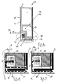
- Figure 1 is a schematic sectional view of a built-in refrigerator according to the present invention;
- Figure 2 is a rear perspective view the bottom portion of the refrigerator of figure 1, where the cooling airflow pattern is shown;
- Figure 3 is a cross section along line III-III of figure 1; and
- Figures 4 and 5 are enlarged views of a portion of figure 1, according to two different systems of built-in installation.
- With reference to figure 1, with 10 is indicated a built-in refrigerator installed in a standard cavity C defined by a rear house wall W and side furniture walls P (figure 3). The built-in refrigerator 10 has an upper refrigeration compartment 10a and a lower freezer compartment 10b. There are different solutions in terms of air circulation in standard cavities, and this can vary from country to country. Two different solutions are shown in figures 4 and 5, with different airflow patterns.
- In every case between the refrigerator and a bottom wall B of the furniture a space K is defined. In the solutions shown in figure 4, normally used for instance in Italy, air flows in the space K toward a
fan 12 and under the bottom wall B of the furniture. In the solution shown in figure 5, typical for built-in appliances in Germany and Switzerland, the wooden door D of the furniture closes the space K, and therefore the air can flow only under the bottom wall B of the furniture for reaching thefan 12. - The
fan 12, acondenser 14 and acompressor 16 are contained in aniche 18 defined in the basement of the refrigerator 10. Theniche 18 has an open rear portion 18a facing the wall W where the refrigerator is installed. Between thecondenser 14, placed downstream thefan 12, and thecompressor 16 there is provided apartition wall 20 whose function is to create an U-shaped air flow around thepartition 20. - The air taken from the external ambient is forced to pass through the
condenser 14 and thecompressor 16, as there is still a potential for heat transfer with the compressor, since it is at a higher temperature. A preferable path with a low pressure drop is created for the air going out after passing throughcondenser 14 andcompressor 16, without going back to the fan inlet region. - The above desired flow pattern is obtained by sealing the inlet region of the
fan 12. This is realised by adding to an upper edge of the rear portion 18a of theniche 18 and to the rear edge of the partition wall 20 a L-shaped rubber gasket 22 which abuts against the wall W on which the refrigerator 10 is placed. Other kinds of gasket can be used, for instance made by foamed polypropilene or similar foamed polymeric material. The use of thegasket 22 avoids air recirculation between high pressure and low pressure areas as this means a very good air flow and performance. Thegasket 22 is fixed to a corresponding L-shaped seat 22a (figure 2) by means of adhesive or known fastening means. - In the solution according to the invention the air pushed by the
fan 12 passes through thecondenser 14 first, then through thecompressor 16 and finally escapes from thecompressor niche 18 towards a space H defined between the rear wall of the refrigerator 10 and the house wall W. - In figures 2 and 3 the arrows show the main air flow pattern where air is sucked mainly from a
bottom front portion 21 of the refrigerator 10 and is discharged in the interpsace H that acts like a chimney. - Tests carried out by the applicant on a refrigerator according to the present invention have shown a surprising improvement in term of appliance performances, of the order of 8%. The following tables show a comparison between a built-in refrigerator according to the invention ("improved configuration") and an identical built-in refrigerator without the sealing gasket ("original configuration").
Steady state @32°C Original configuration Improved configuration [°C] [°C] Average Refrigerator -3,0 -5,0 Average Freezer -26,8 -30,0 Compressor 86,8 71,0 Condenser 59,7 47,7 Dryer 57,8 47,0 Suction tube 44,1 33,2 Voltage [V] 230 230 Current [A] 0,60 0,52 Power [W] 111 98 ISO Energy Consumption test @25°C Original configuration Improved configuration [°C] [°C] Energy Consumption [Wh/24h] 1150 1061 Refrigerator temperature 5,0 5,0 Warmest package temperature -19,7 -20,1 Running time [%] 39,4% 37,5% Cycles/hour 1,0 1,0 Improvement [%] -7,7%
Claims (7)
- Household refrigerator of the built-in type, comprising a refrigerated compartment and a base portion containing a condenser, a fan and a compressor, said base portion having an open rear face adapted to face a house wall (W) where the refrigerator is adapted to be installed, characterised in that the rear face of the base portion is provided with sealing means (22) adapted to cooperate with said house wall (W) in order to define an air suction mouth upstream the condenser (14).
- Household refrigerator according to claim 1, characterised in that it comprises a partition wall (20) placed between the condenser (14) and the compressor (16) in order to cool the compressor downstream the condenser.
- Household refrigerator according to claim 2, characterised in that the cooling air downstream the compressor (16) is discharged in an interspace (H) between the refrigerator (10) and the house wall (W).
- Household refrigerator according to any of the preceding claims, characterised in that the base portion has an open front defining a mouth (21) for the suction of cooling air.
- Household refrigerator according to claim 4, characterised in that said open front of the base portion has a reduced height compared to the rear part thereof.
- Household refrigerator according to any of the preceding claims, characterised in that the sealing means comprise an elastic rubber gasket (22) placed around an edge of the top wall of the base portion and an edge of the partition wall (20) between the condenser (14) and the compressor (16).
- Household refrigerator according to any of claims 1-5, characterised in that the sealing means comprise a gasket (22) made of foamed polymeric material around an edge of the top wall of the base portion and an edge of the partition wall (20) between the condenser (14) and the compressor (16).
Priority Applications (1)
| Application Number | Priority Date | Filing Date | Title |
|---|---|---|---|
| EP03023820A EP1526348A1 (en) | 2003-10-20 | 2003-10-20 | Built-in refrigerator |
Applications Claiming Priority (1)
| Application Number | Priority Date | Filing Date | Title |
|---|---|---|---|
| EP03023820A EP1526348A1 (en) | 2003-10-20 | 2003-10-20 | Built-in refrigerator |
Publications (1)
| Publication Number | Publication Date |
|---|---|
| EP1526348A1 true EP1526348A1 (en) | 2005-04-27 |
Family
ID=34384578
Family Applications (1)
| Application Number | Title | Priority Date | Filing Date |
|---|---|---|---|
| EP03023820A Withdrawn EP1526348A1 (en) | 2003-10-20 | 2003-10-20 | Built-in refrigerator |
Country Status (1)
| Country | Link |
|---|---|
| EP (1) | EP1526348A1 (en) |
Cited By (3)
| Publication number | Priority date | Publication date | Assignee | Title |
|---|---|---|---|---|
| CN106679278A (en) * | 2016-12-09 | 2017-05-17 | 青岛海尔股份有限公司 | Cold-storage refrigerating device |
| CN114198967A (en) * | 2020-09-18 | 2022-03-18 | 合肥美的电冰箱有限公司 | Refrigerator compartment and refrigerator |
| EP4067785A1 (en) * | 2021-03-30 | 2022-10-05 | Whirlpool Corporation | Refrigerator appliance |
Citations (5)
| Publication number | Priority date | Publication date | Assignee | Title |
|---|---|---|---|---|
| JPH05203324A (en) * | 1992-01-30 | 1993-08-10 | Matsushita Refrig Co Ltd | Refrigerator |
| JPH07294094A (en) * | 1994-04-26 | 1995-11-10 | Matsushita Refrig Co Ltd | Cooling storage shed |
| JPH08189749A (en) * | 1995-01-13 | 1996-07-23 | Matsushita Refrig Co Ltd | Refrigerator |
| JPH08285438A (en) * | 1995-04-17 | 1996-11-01 | Matsushita Refrig Co Ltd | Refrigerator |
| DE19933603A1 (en) * | 1999-07-17 | 2001-01-18 | Aeg Hausgeraete Gmbh | Cooling or freezing apparatus for installation in furniture surround has in lower region of back side of apparatus, niche in which compressor, liquefier and fan are located with opening downwards |
-
2003
- 2003-10-20 EP EP03023820A patent/EP1526348A1/en not_active Withdrawn
Patent Citations (5)
| Publication number | Priority date | Publication date | Assignee | Title |
|---|---|---|---|---|
| JPH05203324A (en) * | 1992-01-30 | 1993-08-10 | Matsushita Refrig Co Ltd | Refrigerator |
| JPH07294094A (en) * | 1994-04-26 | 1995-11-10 | Matsushita Refrig Co Ltd | Cooling storage shed |
| JPH08189749A (en) * | 1995-01-13 | 1996-07-23 | Matsushita Refrig Co Ltd | Refrigerator |
| JPH08285438A (en) * | 1995-04-17 | 1996-11-01 | Matsushita Refrig Co Ltd | Refrigerator |
| DE19933603A1 (en) * | 1999-07-17 | 2001-01-18 | Aeg Hausgeraete Gmbh | Cooling or freezing apparatus for installation in furniture surround has in lower region of back side of apparatus, niche in which compressor, liquefier and fan are located with opening downwards |
Non-Patent Citations (4)
| Title |
|---|
| PATENT ABSTRACTS OF JAPAN vol. 017, no. 645 (M - 1517) 30 November 1993 (1993-11-30) * |
| PATENT ABSTRACTS OF JAPAN vol. 1996, no. 03 29 March 1996 (1996-03-29) * |
| PATENT ABSTRACTS OF JAPAN vol. 1996, no. 11 29 November 1996 (1996-11-29) * |
| PATENT ABSTRACTS OF JAPAN vol. 1997, no. 03 31 March 1997 (1997-03-31) * |
Cited By (6)
| Publication number | Priority date | Publication date | Assignee | Title |
|---|---|---|---|---|
| CN106679278A (en) * | 2016-12-09 | 2017-05-17 | 青岛海尔股份有限公司 | Cold-storage refrigerating device |
| CN106679278B (en) * | 2016-12-09 | 2023-09-22 | 海尔智家股份有限公司 | Refrigeration and freezing equipment |
| CN114198967A (en) * | 2020-09-18 | 2022-03-18 | 合肥美的电冰箱有限公司 | Refrigerator compartment and refrigerator |
| CN114198967B (en) * | 2020-09-18 | 2023-11-10 | 东芝家用电器制造(南海)有限公司 | Refrigerator compartment and refrigerator |
| EP4067785A1 (en) * | 2021-03-30 | 2022-10-05 | Whirlpool Corporation | Refrigerator appliance |
| US11573047B2 (en) | 2021-03-30 | 2023-02-07 | Whirlpool Corporation | Refrigerator appliance |
Similar Documents
| Publication | Publication Date | Title |
|---|---|---|
| US12104842B2 (en) | Refrigerator having centrifugal fan with volute | |
| KR20020004962A (en) | Refrigerator | |
| AU2018402915A1 (en) | Recessed refrigerator | |
| EP1384963B1 (en) | Built-in refrigerator | |
| KR20180080082A (en) | Refrigerator | |
| JP4189253B2 (en) | Cooling storage | |
| US7216493B2 (en) | Refrigerator methods and apparatus | |
| CN114174742A (en) | Refrigerator capable of improving air circulation in mechanical room | |
| US7673463B2 (en) | Cooling system methods and apparatus for a refrigeration device | |
| JP2007071521A (en) | refrigerator | |
| CN220750479U (en) | Refrigeration equipment | |
| CN220750485U (en) | Refrigerating apparatus | |
| CN220750480U (en) | Refrigerating apparatus | |
| CN221483953U (en) | Refrigeration equipment | |
| JPH0618186Y2 (en) | refrigerator | |
| CN220229680U (en) | Refrigerator with a refrigerator body | |
| CN222578598U (en) | Refrigerator with a refrigerator body | |
| CN111365926B (en) | A refrigerator based on a simple air duct device for earthquake resistance, condensation prevention and fire prevention | |
| KR20250044086A (en) | Refrigerator | |
| EP3945270A1 (en) | No-frost refrigerator appliance | |
| KR100436274B1 (en) | Refrigerator | |
| JP3966359B1 (en) | refrigerator | |
| JP2001099537A (en) | Refrigerator | |
| KR100587294B1 (en) | Heat dissipation system of built-in refrigerator | |
| KR100436269B1 (en) | Air Conditioner |
Legal Events
| Date | Code | Title | Description |
|---|---|---|---|
| PUAI | Public reference made under article 153(3) epc to a published international application that has entered the european phase |
Free format text: ORIGINAL CODE: 0009012 |
|
| AK | Designated contracting states |
Kind code of ref document: A1 Designated state(s): AT BE BG CH CY CZ DE DK EE ES FI FR GB GR HU IE IT LI LU MC NL PT RO SE SI SK TR |
|
| AX | Request for extension of the european patent |
Extension state: AL LT LV MK |
|
| 17P | Request for examination filed |
Effective date: 20051012 |
|
| AKX | Designation fees paid |
Designated state(s): DE FR GB IT |
|
| 17Q | First examination report despatched |
Effective date: 20070307 |
|
| STAA | Information on the status of an ep patent application or granted ep patent |
Free format text: STATUS: THE APPLICATION IS DEEMED TO BE WITHDRAWN |
|
| 18D | Application deemed to be withdrawn |
Effective date: 20160503 |