EP1526061A2 - Power-assisted steering system and compensating method for the difference in currents from a currents detector - Google Patents
Power-assisted steering system and compensating method for the difference in currents from a currents detector Download PDFInfo
- Publication number
- EP1526061A2 EP1526061A2 EP04025239A EP04025239A EP1526061A2 EP 1526061 A2 EP1526061 A2 EP 1526061A2 EP 04025239 A EP04025239 A EP 04025239A EP 04025239 A EP04025239 A EP 04025239A EP 1526061 A2 EP1526061 A2 EP 1526061A2
- Authority
- EP
- European Patent Office
- Prior art keywords
- current
- detected
- phase
- detector
- value
- Prior art date
- Legal status (The legal status is an assumption and is not a legal conclusion. Google has not performed a legal analysis and makes no representation as to the accuracy of the status listed.)
- Withdrawn
Links
- 238000000034 method Methods 0.000 title claims description 29
- 230000007246 mechanism Effects 0.000 claims description 8
- 230000001105 regulatory effect Effects 0.000 description 15
- 238000004519 manufacturing process Methods 0.000 description 11
- 208000024335 physical disease Diseases 0.000 description 8
- 238000010586 diagram Methods 0.000 description 6
- 230000008569 process Effects 0.000 description 6
- 230000000694 effects Effects 0.000 description 5
- 230000001131 transforming effect Effects 0.000 description 5
- 230000006870 function Effects 0.000 description 3
- 230000010354 integration Effects 0.000 description 3
- 230000004913 activation Effects 0.000 description 2
- 230000001276 controlling effect Effects 0.000 description 2
- 238000001514 detection method Methods 0.000 description 2
- 230000033001 locomotion Effects 0.000 description 2
- 238000004804 winding Methods 0.000 description 2
- 230000008901 benefit Effects 0.000 description 1
- 230000008878 coupling Effects 0.000 description 1
- 238000010168 coupling process Methods 0.000 description 1
- 238000005859 coupling reaction Methods 0.000 description 1
- 238000007689 inspection Methods 0.000 description 1
- 238000011112 process operation Methods 0.000 description 1
- 230000007363 regulatory process Effects 0.000 description 1
- 238000003860 storage Methods 0.000 description 1
- 230000009466 transformation Effects 0.000 description 1
Images



Classifications
-
- B—PERFORMING OPERATIONS; TRANSPORTING
- B62—LAND VEHICLES FOR TRAVELLING OTHERWISE THAN ON RAILS
- B62D—MOTOR VEHICLES; TRAILERS
- B62D5/00—Power-assisted or power-driven steering
- B62D5/04—Power-assisted or power-driven steering electrical, e.g. using an electric servo-motor connected to, or forming part of, the steering gear
- B62D5/0457—Power-assisted or power-driven steering electrical, e.g. using an electric servo-motor connected to, or forming part of, the steering gear characterised by control features of the drive means as such
- B62D5/046—Controlling the motor
- B62D5/0463—Controlling the motor calculating assisting torque from the motor based on driver input
-
- B—PERFORMING OPERATIONS; TRANSPORTING
- B62—LAND VEHICLES FOR TRAVELLING OTHERWISE THAN ON RAILS
- B62D—MOTOR VEHICLES; TRAILERS
- B62D5/00—Power-assisted or power-driven steering
- B62D5/04—Power-assisted or power-driven steering electrical, e.g. using an electric servo-motor connected to, or forming part of, the steering gear
- B62D5/0457—Power-assisted or power-driven steering electrical, e.g. using an electric servo-motor connected to, or forming part of, the steering gear characterised by control features of the drive means as such
- B62D5/046—Controlling the motor
-
- H—ELECTRICITY
- H02—GENERATION; CONVERSION OR DISTRIBUTION OF ELECTRIC POWER
- H02P—CONTROL OR REGULATION OF ELECTRIC MOTORS, ELECTRIC GENERATORS OR DYNAMO-ELECTRIC CONVERTERS; CONTROLLING TRANSFORMERS, REACTORS OR CHOKE COILS
- H02P6/00—Arrangements for controlling synchronous motors or other dynamo-electric motors using electronic commutation dependent on the rotor position; Electronic commutators therefor
- H02P6/10—Arrangements for controlling torque ripple, e.g. providing reduced torque ripple
-
- H—ELECTRICITY
- H02—GENERATION; CONVERSION OR DISTRIBUTION OF ELECTRIC POWER
- H02P—CONTROL OR REGULATION OF ELECTRIC MOTORS, ELECTRIC GENERATORS OR DYNAMO-ELECTRIC CONVERTERS; CONTROLLING TRANSFORMERS, REACTORS OR CHOKE COILS
- H02P6/00—Arrangements for controlling synchronous motors or other dynamo-electric motors using electronic commutation dependent on the rotor position; Electronic commutators therefor
- H02P6/28—Arrangements for controlling current
-
- B—PERFORMING OPERATIONS; TRANSPORTING
- B60—VEHICLES IN GENERAL
- B60W—CONJOINT CONTROL OF VEHICLE SUB-UNITS OF DIFFERENT TYPE OR DIFFERENT FUNCTION; CONTROL SYSTEMS SPECIALLY ADAPTED FOR HYBRID VEHICLES; ROAD VEHICLE DRIVE CONTROL SYSTEMS FOR PURPOSES NOT RELATED TO THE CONTROL OF A PARTICULAR SUB-UNIT
- B60W2510/00—Input parameters relating to a particular sub-units
- B60W2510/22—Suspension systems
- B60W2510/225—Damping
Definitions
- the present invention relates to a power-assisted steering system in which a steering mechanism of a vehicle is provided with an auxiliary steering force by driving an electric motor.
- the electric motor driving device includes a PWM signal generating circuit for generating a pulse width modulation signal (hereinafter, referred to as a "PWM signal") having a duty ratio which corresponds to the command value and a motor driving circuit which is configured by utilizing a power transistor which is on and off in accordance with the duty ratio of the PWM signal and applies to the electric motor a voltage which corresponds to the duty ratio.
- PWM signal pulse width modulation signal
- a current caused to flow to the electric motor by the application of the voltage is detected by a current detector, and a difference between the target current value and the detected current value so detected is used as a deviation for generating the command value.
- the reference current detector which is accurately regulated has to be prepared. Furthermore, since it cannot be avoided that a predetermined error is generated when regulating the output value of the current detector, it is normal that the output value of the reference current detector does not coincide with the corrected or regulated output value of each current detector completely.
- the (relative) deviation becomes relatively large. As this occurs, the aforesaid torque ripple may take place, causing thereby the driver to feel a feeling of physical disorder when turning the steering wheel.
- an object of the invention is to provide a power-assisted steering system which can provide a steering feel which is free from a feeling of physical disorder by suppressing a torque ripple which occurs as the effect of a gain difference between respective current detectors.
- the invention is characterized by having the following arrangement.
- the gain correcting coefficient is calculated based on the detected current values of the current which flows only to the current detector for the phase constituting a reference (for example, a U-phase) and the current detector for the other phase (for example, a V-phase) by opening the one or more motor terminals (for example, one of a W-phase), whereby since the gain correcting coefficient can be calculated in a simple method, the generation of a torque ripple due to the gain difference between the respective current detector can be suppressed simply, thereby making it possible to providing the driver with a steering feel which is free from a feeling of physical disorder.
- the gain difference of the other current detector relative to the current detector which constitutes a reference is compensated for based the detected current values which are detected by opening the one or more motor terminals (for example, the one end of the W-phase) and making the same current to flow to the two current detector by applying the predetermined voltage between the terminals which are not opened (for example, between the U-phase and V-phase) , whereby the generation of the torque ripple due to the gain difference between the respective current detector can be suppressed simply, thereby making it possible to provide the driver with a steering feel which is free from a feeling of physical disorder.
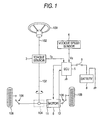
- Fig. 1 is a schematic diagram showing the configuration of an electric power-assisted steering system according to an embodiment of the invention, together with the configuration of a vehicle which is associated with the electric power-assisted steering system.
- This electric power-assisted steering system includes a steering shaft 102 which is connected at one end thereof to a steering wheel 100 as a manipulating device for steering, a rack and pinion mechanism 104 coupled to the other end of the steering shaft 102, a torque sensor 3 for detecting a steering torque Ts exerted on the steering shaft 102 through the manipulation of the steering wheel 100, a vehicle speed sensor 4 for detecting a running speed Vs of the vehicle, a brushless motor 6 for generating an auxiliary steering force to reduce a load borne by the driver when manipulating the steering wheel 100, a ball screw driving portion 11 for transmitting the auxiliary steering force to a rack shaft, a position detecting sensor 12 for detecting the rotational position of a rotor of the brushless motor 6 and an electronic control unit (ECU) 5 which
- Fig. 2 is a block diagram showing the configuration of the ECU 5, which is a control system in the electric power-assisted steering system.
- the ECU 5 is constituted by a microcomputer 10 and a motor driving unit.
- the microcomputer 10 functions a motor control unit which includes a vehicle speed calculating unit 184, a target current calculating unit 114, subtracters 122, 124, a d-axis current PI control unit 126, a q-axis current PI control unit 128, a d-q/3-phase alternating current coordinate transforming unit 132, a sign reversal adder 134, a 3-phase/d-q coordinate transforming unit 138 and a detected current value correcting unit 170.
- a motor control unit which includes a vehicle speed calculating unit 184, a target current calculating unit 114, subtracters 122, 124, a d-axis current PI control unit 126, a q-axis current PI control unit 128, a d
- the target current calculating unit 114 includes a basic assistance control unit 180 and a motor current command value calculating unit 188.
- the motor driving unit is a hardware (circuit) for driving the 3-phase brushless motor 6 based on a voltage command value output from the microcomputer 10 and includes a PWM signal generating circuit 150, a motor driving circuit 152, a U-phase current detector 156, a V-phase current detector 154 and a rotor angular position detector 162.
- a relay (not shown) is provided in the ECU 5, and the power supply is supplied to the motor driving unit and the brushless motor 6 while the relay is closed.
- a steering torque Ts detected by the torque sensor 3 is input into the ECU 5, and a vehicle speed signal Vs detected by the vehicle speed sensor 4 is also input into the ECU 5.
- a vehicle speed V is calculated based on the vehicle speed signal Vs so detected in the vehicle speed calculating unit 184.
- the rotor angular position detector 162 outputs a signal indicating the rotational position or an electric angle ⁇ re of a revolving field (a permanent magnet) which is a rotor of the motor 6 based on a sensor signal output from the position detecting sensor 12 mounted on the motor.
- the basic assistance control unit 180 determines a target current value It which should be made to flow to the motor 6 based on the steering torque Ts and the vehicle speed V while referring to a table called an assistance map which establishes a correspondence between the steering torque and the target current value.
- the motor current command value calculating unit 188 outputs a q-axis current command value iq* based on the target current value It.
- This q-axis current command value iq* is a current value which corresponds to a torque that is to be generated by the motor 6 and is input into the subtracter 124.
- the U-phase current detector 156 and the V-phase current detector 154 detect current flowing to a U-phase winding and a V-phase winding (in this specification, referred to simply as "U-phase, V-phase", respectively) of the motor, respectively, and output a U-phase detected current value iu and a V-phase detected current value iv in the form of a voltage signal. While these U-phase current detector 156 and the V-phase current detector 154 are disposed relative to lines connecting from the motor driving circuit 152 to the motor 6, the respective detectors may be disposed between respective driving devices within the motor driving circuit 152 and a grounded point. Note that as has been described before, the intrinsic gain difference are included in the U-phase detected current value iu and the V-phase detected current value iv.
- the detected current value correcting unit 170 corrects the U-phase detected current value iu by subtracting the corresponding offset correction value from the U-phase detected current value iu and outputs a U-phase motor current value imu based on a detected current value so corrected.
- the detected current value correcting unit 170 corrects the V-phase detected current value iv by subtracting a corresponding offset correction value from the V-phase detected current value iv and multiplying a value obtained through the subtraction by a V-phase gain correcting coefficient, which will be described later on, in such a manner that a gain value of the V-phase current detector 154 becomes equivalent to the gain value of the U-phase current detector 156 as a result (nominally) and outputs a V-phase detected current value iv based on the corrected current value.
- the gain difference of the V-phase current detector 154 relative to the U-phase current detector 156 is eliminated as a result of the multiplication by the gain correcting coefficient. Namely, since a relative detection error caused by the gain difference between the current detectors is eliminated, a torque ripple generated based on the gain difference of each current detector is reduced.
- the detected current value of the V-phase current detector 154 relative to the gain of the U-phase current detector 156 is corrected using the gain as the reference, in case there exists a deviation between a true current value which flows to the U-phase and the detected current value by the U-phase current detector 156, the detected current value of the V-phase current detector also generates the same deviation. Thus, it is considered that the torque of the motor 6 which is actually obtained deviates from the ideal value by the deviation generated between the actual gain of each current detector and the (designed) ideal gain.
- a deviation id*-id between the d-axis current command value id* and the d-axis motor current value id is output from the subtracter 122. Then, a d-axis voltage command value vd* is output from the d-axis current PI control unit 126 through a proportional integration operation based on the deviation id*-id so output. On the other hand, a deviation iq*-iq between the q-axis current command value iq* and the q-axis motor current value iq is output from the subtracter 124. Then, a q-axis voltage command value vq* is output from the q-axis current PI control unit 128 through a proportional integration operation based on the deviation iq*-iq so output.
- the d-q/3-phase alternating current coordinate transforming unit 132 transforms the d-axis voltage command value vd* and the q-axis voltage command value vq* into a U-phase voltage command value v* and a V-phase voltage command value vv* which are values on a 3-phase alternating current coordinate based on the electric angle ⁇ re of the rotor. Then, the sign reversal adder 134 calculates a W-phase voltage command value vw* from the U-phase voltage command value vu* and the V-phase voltage command value vv*.
- the PWM signal generating circuit 150 receives the U-phase voltage command value vu*, the V-phase voltage command value vv* and the W-phase voltage command value vw* and generates PWM signals Su, Sv, Sw whose duty ratios vary in accordance with the command values so received.
- the motor driving circuit 152 switching devices are switched on and off by the PWM signals Su, Sv, Sw so generated, whereby voltages vu, vv, vw which correspond to the duty ratios are applied to the U-phase, V-phase and W-phase of the motor 6, respectively.
- Fig. 3 is a flowchart illustrating a correcting procedure of detected current values. Note that the function of the detected current value correcting unit 170 shown in Fig- 2 is realized in processing steps shown as step S130 and S150 in the flowchart.
- step S110 when an ignition switch 9 is switched on (step S110), the microcomputer 10 sets a value set in advance at the time of production to a v-phase gain correcting coefficient gv, which is a parameter.
- a v-phase gain correcting coefficient gv which is a parameter.
- step S140 the relay is closed (put in an ON state), and in step S150, the detected current value correcting unit 170 corrects the U-phase detected current value iu by subtracting the U-phase offset correction value iou from the U-phase detected current value iu and outputs the U-phase motor current value imu.
- the detected current value correcting unit 170 corrects the V-phase detected current value iv by subtracting the V-phase offset correction value iov from the V-phase detected current value iv and multiplying the value obtained through the subtraction by the reciprocal number of the predetermined reference gain value and outputs the V-phase motor current value imv. Then, the conventional motor driving process is performed based on these output current values.
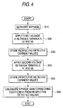
- Fig. 4 is a flowchart illustrating a calculation procedure of a V-phase gain correcting coefficient. Note that here, it is understood that a V-phase gain correcting coefficient is calculated at the time of producing (regulating) the electric power-assisted steering system of the invention. In addition, while the following calculating procedure is executed by a predetermined software stored in the microcomputer 10, the calculating procedure may be executed by a predetermined regulating system (or an inspection system) , which is such as other than the electric power-assisted steering system of the invention, for calculating a V-phase gain correcting coefficient.
- Fig. 5 is a diagram illustrating the connection to the motor 6.
- the motor 6 is connected in a Y-connection, in which a terminal 61 is connected to one end of a U-phase wiring, a terminal 62 is connected to one end of a V-phase wiring, and a terminal 63 is connected to one end of a W-phase wiring.
- a switch 65 passes or cuts off (on or off) current to the w-phase wiring.
- This switch 65 is, for example, a relay that is controlled by the microcomputer 10.
- step S10 shown in Fig. 4 the switch 65 is switched off in order to electrically separate from the other phases, whereby the terminal 63 is released and the W-phase is put in a state where no current passes therethrough.
- a first voltage v1 is applied between the terminal 61 and the terminal 62, whereby the first current v1 is allowed to flow to the U-phase and V-phase, respectively.
- the value of this first current can be obtained by accurately measuring the current with, for example, a current detector which is prepared in advance outside the system so as to constitute a reference, or calculating from the first voltage v1 value and a resistance value between the terminal 61 and the terminal 62, as will be described later on, the value of the first current i1 does not have to be obtained here.
- step S30 an output value (a detected current value) Xu and an output value (a detected current value) Xv which are output from the U-phase current detector 156 and the V-phase current detector 154, respectively, then (namely, in a state where the first current i1 flows) are stored.
- step S40 a second voltage v2 is applied between the terminal 61 and the terminal 62, whereby second current is allowed to flow to the U-phase and V-phase, respectively. Note that as with the first current i1, this second voltage i2 does not have to be obtained.
- step S50 an output value (a detected current value) Yu and an output value (a detected current value) Yv which are output from the U-phase current detector 156 and the V-phase current detector 154, respectively, then (namely, in a state where the second current i2 flows) are stored.
- a V-phase gain correcting coefficient is calculated based on the detected current value so stored.
- the V-phase gain correcting coefficient is a coefficient by which the detected current value which has been offset corrected is multiplied in such a manner that the gain difference of the V-phase current detector 154 relative to the U-phase current detector 156 is eliminated as a result, and to be specific, the coefficient is a reciprocal number of a ratio of the gain value of the V-phase current detector 154 relative to the U-phase current detector 156.
- a gain value Au of the U-phase current detecting unit 156 is expressed by the following equation (1) as below.
- V-phase gain correcting coefficient gv that has been calculated as has been described above is stored in a storage unit (for example, EEPROM) , not shown, of the microcomputer 10 for reference when the system is activated.
- the V-phase gain correcting coefficient gv can be calculated irrespective of the values of the first and second currents i1, i2, the first and second voltages v1, v2 do not have to be applied accurately. Due to this, the V-phase gain correcting coefficient can be calculated by the simple method without using a current detector which is accurately regulated so as to constitute a reference or various types of devices for applying accurate voltages, thereby making it possible to suppress the generation of a torque ripple due to the gain difference between the respective current detectors.
- the V-phase gain correcting coefficient gv can be calculated irrespective of the values of the first and second currents i1, i2, the offset correction values do not have to be calculated in advance at the time of production.
- various types of known offset correcting methods can be applied.
- first and second voltages v1, v2 may take any voltage, provided that the voltage so taken can be applied to the motor 6, it is preferred that typically, the first voltage v1 takes a maximum voltage value that is to be applied to at the time of activation, whereas the second voltage v2 takes a minimum voltage value that is to be so applied. Then, since the values of
- the first voltage v1 is a maximum voltage value within a range where the gain values of the U-phase current detector 156 and the V-phase current detector 154 do not vary (or vary little)
- the second voltage v2 is a minimum voltage value within the same range. If this becomes true, since the values of
- the detected current value of the v-phase current detector 154 is corrected based on the V-phase gain correcting coefficient calculated using the U-phase current detector 156 as the reference by releasing the one end (the terminal 63) of the W-phase of the motor 6 so as to allow the passage of the first and second currents i1, i2, whereby the gain difference can compensated for and the generation of torque ripple due to the gain difference between the respective current detectors can be suppressed, thereby making it possible to provide the driver with a steering feel which is free from a feeling of physical disorder.
- the V-phase gain correcting coefficient is described as being calculated at the time of producing (regulating) the electric power-assisted steering system of the invention, the coefficient may be calculated at an initial activation of the system or every time the system is activated.
- the microcomputer 10 activated based on the predetermined software which is stored in advance that executes the calculating procedure (refer to Fig.
- a U-phase gain correcting coefficient for correcting the U-phase detected current value iu may be calculated using the V-phase current detector 154 as the reference.
- the corresponding offset correction values are set based on the U-phase detected current value iu and the V-phase detected current value iv which result when the ignition switch is switched on, as has been described before, since the calculation of the V-phase gain correcting coefficient for compensating for the gain difference and the offset correction have no relation at all therebetween, various known methods can be used for the offset correction.
- the offset correction values may be set at the time of production, and furthermore, the corresponding offset correction values may be updated based on the U-phase detected current value iu and the V-phase detected current value iv which result when the ignition switch is switched on. Note that setting the offset correction values at the time of production is preferable in that a torque ripple component of the motor 6 can be inspected at the time of production. In addition, in case the offset correction values are relatively small, the offset correction may be omitted.
- a predetermined voltage may be applied to the respective terminals 61 to 63 in Fig. 5 in such a manner that the same current is allowed to flow to the U-phase and the V-phase.
- the current flowing to the U-phase and the V-phase is described as being detected by the u-phase current detector 156 and the V-phase current detector 154, current flowing to the W-phase may be detected by providing further a W-phase current detector.
- a W-phase gain correcting coefficient for correcting the W-phase detected current value using the U-phase current detector 156 as the reference needs to be calculated.
- the motor 6 is the 3-phase brushless motor, the motor may be an n-phase (n is an integer equal to or larger than 4) brushless motor.
- the invention may be applied for detection of a current flowing to the electric motor.
Landscapes
- Engineering & Computer Science (AREA)
- Chemical & Material Sciences (AREA)
- Combustion & Propulsion (AREA)
- Transportation (AREA)
- Mechanical Engineering (AREA)
- Power Engineering (AREA)
- Power Steering Mechanism (AREA)
- Steering Control In Accordance With Driving Conditions (AREA)
- Control Of Motors That Do Not Use Commutators (AREA)
- Control Of Ac Motors In General (AREA)
Abstract
Description
In step S10 shown in Fig. 4, the
Claims (3)
- A power-assisted steering system in which a steering mechanism of a vehicle is provided with an auxiliary steering force by driving a brushless motor having three or more phases and terminals based on a target current value determined in accordance with an operation for steering the vehicle, the power-assisted steering system comprising:two or more current detectors that detects current flowing to two or more of the phases of the brushless motor, respectively, and outputs detected current values, the current detectors respectively including inherent gain values;a correcting unit that corrects the detected current values output from the two or more current detectors so as to compensate a difference in gain between the current detectors; anda motor driving driver that drives the brushless motor based on a deviation between the target current value and detected current values which are corrected by the correcting unit; whereinwhen the same current flows to the phase in which the current flowing thereto is detected by one of the two or more current detectors which constitutes a reference and the phase in which the current flowing thereto is detected by the other current detector of the two or more current detectors, the correcting unit calculates a gain correcting coefficient for compensating for a gain difference of the other current detector relative to the current detector which constitutes the reference based on a detected current value of the current detector which constitutes the reference and a detected current value of the other current detector and corrects the detected current value of the other current detector based on the calculated gain correcting coefficient.
- The power-assisted steering system according to claim 1, wherein the correcting unit makes the same current flow to the respective phases in which the current flowing thereto is detected by the current detector which constitutes the reference and the other current detector, respectively, by opening one or more of the terminals and calculates the gain correcting coefficient based on detected current values of the same current.
- A method for compensating for a gain difference between two or more current detector which are provided on a power-assisted steering system in which a steering mechanism of a vehicle is provided with an auxiliary steering force by driving a brushless motor having three or more phases and terminals based on a target current value determined in accordance with an operation for steering the vehicle and which is adapted to detect current flowing to predetermined phases possessed by the brushless motor and to output the detected current values, the compensating method comprising:an opening step of opening one or more of the terminals so that the same current is made to flow to phases of the three or more phases in which current flowing thereto is detected by two of the two or more current detectors which include a current detector which constitutes a reference, respectively;a voltage applying step of making the same current to flow to the two current detectors by applying a predetermined voltage between the terminals which are not opened in the opening step; anda correcting step of compensating for a gain difference of the other current detector relative to the current detector which constitutes a reference based on detected current values which are obtained by detecting the same current which is made to flow in the voltage applying step by the two current detectors.
Applications Claiming Priority (2)
| Application Number | Priority Date | Filing Date | Title |
|---|---|---|---|
| JP2003361770A JP4474894B2 (en) | 2003-10-22 | 2003-10-22 | Power steering device and gain difference compensation method for current detection means |
| JP2003361770 | 2003-10-22 |
Publications (2)
| Publication Number | Publication Date |
|---|---|
| EP1526061A2 true EP1526061A2 (en) | 2005-04-27 |
| EP1526061A3 EP1526061A3 (en) | 2016-11-09 |
Family
ID=34386499
Family Applications (1)
| Application Number | Title | Priority Date | Filing Date |
|---|---|---|---|
| EP04025239.7A Withdrawn EP1526061A3 (en) | 2003-10-22 | 2004-10-22 | Power-assisted steering system and compensating method for the difference in currents from a currents detector |
Country Status (4)
| Country | Link |
|---|---|
| US (1) | US7226069B2 (en) |
| EP (1) | EP1526061A3 (en) |
| JP (1) | JP4474894B2 (en) |
| KR (1) | KR20050039611A (en) |
Cited By (1)
| Publication number | Priority date | Publication date | Assignee | Title |
|---|---|---|---|---|
| EP1819037A1 (en) * | 2006-02-08 | 2007-08-15 | JTEKT Corporation | Motor controller |
Families Citing this family (16)
| Publication number | Priority date | Publication date | Assignee | Title |
|---|---|---|---|---|
| JP4289458B2 (en) * | 2004-09-07 | 2009-07-01 | 三菱電機株式会社 | Electric power steering control device |
| JP4422593B2 (en) * | 2004-11-22 | 2010-02-24 | 日立オートモティブシステムズ株式会社 | Power steering device |
| CN101193787A (en) * | 2005-06-07 | 2008-06-04 | 株式会社捷太格特 | electric steering system |
| CN101365616B (en) * | 2005-11-23 | 2011-12-21 | Trw汽车美国有限责任公司 | Electrical power assisted steering system |
| JP2007236075A (en) * | 2006-02-28 | 2007-09-13 | Mitsubishi Electric Corp | Electric power steering control device |
| JP2008236868A (en) * | 2007-03-19 | 2008-10-02 | Hitachi Ltd | Load current control device |
| JP5038864B2 (en) | 2007-11-20 | 2012-10-03 | 日立オートモティブシステムズ株式会社 | Seat belt retractor control device and seat belt retractor |
| MX2008014783A (en) | 2008-02-05 | 2009-08-27 | Krueger Int Inc | Chair shell with integral hollow contoured support. |
| JP2010110067A (en) * | 2008-10-29 | 2010-05-13 | Hitachi Automotive Systems Ltd | Motor control device |
| EP2221235B1 (en) | 2009-02-23 | 2011-11-30 | Showa Corporation | Electric power steering apparatus, control method thereof and program |
| KR101357942B1 (en) | 2010-04-20 | 2014-02-04 | 주식회사 만도 | Method and apparatus for compensating voltage drop imbalance, and motor driven power steering system |
| EP2813414B1 (en) * | 2012-02-06 | 2018-04-04 | NSK Ltd. | Electric power steering device |
| EP3214754B1 (en) | 2014-10-30 | 2020-10-14 | Hitachi Automotive Systems, Ltd. | Motor control device |
| JP6521881B2 (en) * | 2016-02-05 | 2019-05-29 | トヨタ自動車株式会社 | Drive unit |
| CN115366984B (en) * | 2021-05-21 | 2023-08-15 | 广州汽车集团股份有限公司 | Torque steering compensation method, device, vehicle and storage medium |
| US12509337B2 (en) | 2023-04-13 | 2025-12-30 | Crown Equipment Corporation | Steering shaft assembly for a materials handling vehicle |
Family Cites Families (13)
| Publication number | Priority date | Publication date | Assignee | Title |
|---|---|---|---|---|
| JPS62283067A (en) * | 1986-05-31 | 1987-12-08 | Aisin Seiki Co Ltd | Electrically driven power steering device |
| JPH0591780A (en) * | 1991-09-27 | 1993-04-09 | Japan Steel Works Ltd:The | Method and device for controlling three-phase motor |
| JP3519830B2 (en) * | 1995-09-01 | 2004-04-19 | 三菱電機株式会社 | Motor control device |
| JP3276840B2 (en) * | 1996-02-13 | 2002-04-22 | フジテック株式会社 | Correction gain setting method for AC elevator control device |
| JP3154665B2 (en) | 1996-08-29 | 2001-04-09 | 三菱電機株式会社 | High-side motor current detection circuit |
| JP3766529B2 (en) * | 1997-12-24 | 2006-04-12 | 株式会社ジェイテクト | Motor control device |
| JP2001327186A (en) * | 2000-05-12 | 2001-11-22 | Matsushita Electric Ind Co Ltd | Current detection device for three-phase synchronous motor |
| JP2002238293A (en) * | 2001-02-14 | 2002-08-23 | Mitsubishi Electric Corp | Motor control device |
| JP3485905B2 (en) * | 2001-04-26 | 2004-01-13 | 本田技研工業株式会社 | Motor control device |
| CA2413379C (en) * | 2001-12-06 | 2010-02-09 | Honda Giken Kogyo Kabushiki Kaisha | Electric power steering apparatus |
| US6808043B2 (en) * | 2002-02-15 | 2004-10-26 | Nsk Ltd. | Electric power steering device |
| JP3674919B2 (en) * | 2002-03-19 | 2005-07-27 | 本田技研工業株式会社 | Electric power steering apparatus and control method thereof |
| JP3914108B2 (en) * | 2002-07-15 | 2007-05-16 | 本田技研工業株式会社 | DC brushless motor control device |
-
2003
- 2003-10-22 JP JP2003361770A patent/JP4474894B2/en not_active Expired - Fee Related
-
2004
- 2004-10-21 KR KR1020040084362A patent/KR20050039611A/en not_active Ceased
- 2004-10-21 US US10/968,948 patent/US7226069B2/en not_active Expired - Fee Related
- 2004-10-22 EP EP04025239.7A patent/EP1526061A3/en not_active Withdrawn
Non-Patent Citations (1)
| Title |
|---|
| None * |
Cited By (1)
| Publication number | Priority date | Publication date | Assignee | Title |
|---|---|---|---|---|
| EP1819037A1 (en) * | 2006-02-08 | 2007-08-15 | JTEKT Corporation | Motor controller |
Also Published As
| Publication number | Publication date |
|---|---|
| EP1526061A3 (en) | 2016-11-09 |
| US7226069B2 (en) | 2007-06-05 |
| US20050087387A1 (en) | 2005-04-28 |
| JP4474894B2 (en) | 2010-06-09 |
| KR20050039611A (en) | 2005-04-29 |
| JP2005130570A (en) | 2005-05-19 |
Similar Documents
| Publication | Publication Date | Title |
|---|---|---|
| US7226069B2 (en) | Power-assisted steering system and difference compensating method for current detector | |
| EP1526060B1 (en) | Power-assisted steering system | |
| EP2159132B1 (en) | Motor control apparatus and electric power steering apparatus | |
| US8862323B2 (en) | Motor control device and vehicle-steering device comprising same | |
| EP2835906B1 (en) | Motor control device and electric power steering device equipped with same | |
| US8890459B2 (en) | Motor control device and electric power steering system | |
| CN102582679B (en) | Electric power steering apparatus | |
| US8008880B2 (en) | Motor controller and electric power steering apparatus | |
| US7889978B2 (en) | Motor controller and electric power steering system | |
| US20110148336A1 (en) | Motor control device and method for controlling brushless motor | |
| US8368343B2 (en) | Motor control device | |
| US7913805B2 (en) | Electric power steering apparatus | |
| US10333440B2 (en) | Motor control apparatus and electric power steering system | |
| EP1849681B1 (en) | Electric power steering apparatus | |
| EP2262099A1 (en) | Motor control device and electric power steering device | |
| US20220289274A1 (en) | Electric power steering apparatus, control device used in electric power steering apparatus, and control method | |
| KR20050020638A (en) | A motor power steering apparatus | |
| JP2005059777A (en) | Electrically powered steering device | |
| JP2008056079A (en) | Motor control device | |
| JP2005001513A (en) | Electric power steering device | |
| US20200269909A1 (en) | Steering controller and steering control method | |
| JP5495019B2 (en) | Motor control device and vehicle steering device |
Legal Events
| Date | Code | Title | Description |
|---|---|---|---|
| PUAI | Public reference made under article 153(3) epc to a published international application that has entered the european phase |
Free format text: ORIGINAL CODE: 0009012 |
|
| AK | Designated contracting states |
Kind code of ref document: A2 Designated state(s): AT BE BG CH CY CZ DE DK EE ES FI FR GB GR HU IE IT LI LU MC NL PL PT RO SE SI SK TR |
|
| AX | Request for extension of the european patent |
Extension state: AL HR LT LV MK |
|
| RAP1 | Party data changed (applicant data changed or rights of an application transferred) |
Owner name: JTEKT CORPORATION |
|
| PUAL | Search report despatched |
Free format text: ORIGINAL CODE: 0009013 |
|
| AK | Designated contracting states |
Kind code of ref document: A3 Designated state(s): AT BE BG CH CY CZ DE DK EE ES FI FR GB GR HU IE IT LI LU MC NL PL PT RO SE SI SK TR |
|
| AX | Request for extension of the european patent |
Extension state: AL HR LT LV MK |
|
| RIC1 | Information provided on ipc code assigned before grant |
Ipc: B62D 5/04 20060101AFI20160930BHEP Ipc: H02P 6/00 20160101ALI20160930BHEP Ipc: H02P 6/10 20060101ALI20160930BHEP |
|
| 17P | Request for examination filed |
Effective date: 20170509 |
|
| RBV | Designated contracting states (corrected) |
Designated state(s): AT BE BG CH CY CZ DE DK EE ES FI FR GB GR HU IE IT LI LU MC NL PL PT RO SE SI SK TR |
|
| RBV | Designated contracting states (corrected) |
Designated state(s): AT BE BG CH CY CZ DE DK EE ES FI FR GB GR HU IE IT LI LU MC NL PL PT RO SE SI SK TR |
|
| AKX | Designation fees paid |
Designated state(s): DE FR |
|
| AXX | Extension fees paid |
Extension state: MK Extension state: HR Extension state: AL Extension state: LT Extension state: LV |
|
| 17Q | First examination report despatched |
Effective date: 20180713 |
|
| STAA | Information on the status of an ep patent application or granted ep patent |
Free format text: STATUS: THE APPLICATION HAS BEEN WITHDRAWN |
|
| 18W | Application withdrawn |
Effective date: 20181120 |
|
| RIC1 | Information provided on ipc code assigned before grant |
Ipc: H02P 6/00 20160101ALI20160930BHEP Ipc: H02P 6/10 20060101ALI20160930BHEP Ipc: B62D 5/04 20060101AFI20160930BHEP |