EP1526037A2 - Headlamp adjuster with expandable member for accommodating retraction of an adjuster output member - Google Patents
Headlamp adjuster with expandable member for accommodating retraction of an adjuster output member Download PDFInfo
- Publication number
- EP1526037A2 EP1526037A2 EP04254436A EP04254436A EP1526037A2 EP 1526037 A2 EP1526037 A2 EP 1526037A2 EP 04254436 A EP04254436 A EP 04254436A EP 04254436 A EP04254436 A EP 04254436A EP 1526037 A2 EP1526037 A2 EP 1526037A2
- Authority
- EP
- European Patent Office
- Prior art keywords
- adjuster
- headlamp
- housing
- expandable member
- recited
- Prior art date
- Legal status (The legal status is an assumption and is not a legal conclusion. Google has not performed a legal analysis and makes no representation as to the accuracy of the status listed.)
- Withdrawn
Links
Images


Classifications
-
- B—PERFORMING OPERATIONS; TRANSPORTING
- B60—VEHICLES IN GENERAL
- B60Q—ARRANGEMENT OF SIGNALLING OR LIGHTING DEVICES, THE MOUNTING OR SUPPORTING THEREOF OR CIRCUITS THEREFOR, FOR VEHICLES IN GENERAL
- B60Q1/00—Arrangement of optical signalling or lighting devices, the mounting or supporting thereof or circuits therefor
- B60Q1/02—Arrangement of optical signalling or lighting devices, the mounting or supporting thereof or circuits therefor the devices being primarily intended to illuminate the way ahead or to illuminate other areas of way or environments
- B60Q1/04—Arrangement of optical signalling or lighting devices, the mounting or supporting thereof or circuits therefor the devices being primarily intended to illuminate the way ahead or to illuminate other areas of way or environments the devices being headlights
- B60Q1/06—Arrangement of optical signalling or lighting devices, the mounting or supporting thereof or circuits therefor the devices being primarily intended to illuminate the way ahead or to illuminate other areas of way or environments the devices being headlights adjustable, e.g. remotely-controlled from inside vehicle
- B60Q1/068—Arrangement of optical signalling or lighting devices, the mounting or supporting thereof or circuits therefor the devices being primarily intended to illuminate the way ahead or to illuminate other areas of way or environments the devices being headlights adjustable, e.g. remotely-controlled from inside vehicle by mechanical means
- B60Q1/0683—Adjustable by rotation of a screw
Definitions
- the present invention relates generally to headlamp adjusters which are used to adjust the position of a reflector of an automobile headlamp assembly, and relates more specifically to a headlamp adjuster which includes an expandable member, such as a bellows, for accommodating an end of an adjuster member when the adjuster member is retracted.
- an expandable member such as a bellows
- Modem day headlamps for vehicles are engineered and designed to be aerodynamically efficient.
- the headlamps are designed as sealed assemblies wherein the portion of the headlamp approximate the outer surface of the automobile is relatively stationary, and is aerodynamic.
- a typical modem day headlamp assembly 12 is illustrated in a plan view seen as FIGURE 1, and normally includes: a fixed housing 20, to which an outer headlamp lens 22 is affixed; a movable reflector 24, which is mounted within the fixed housing 20; and a stationary headlamp bulb (not shown), which is positioned within the movable reflector 24.
- the movable reflector 24 is mounted to the housing 20 by a universal or ball-type pivot 26 which is stationary, or fixed, on the housing 20.
- a first pivot point 28 is disposed generally vertical of the fixed pivot 26, and a second pivot point 30 is disposed generally horizontal of the fixed pivot 26.
- the movable reflector 24 may be pivoted about the fixed pivot 26 in the vertical and horizontal planes to aim the headlamp beam.
- Adjustment mechanisms, or headlamp adjusters, 40 and 42 are typically provided at the first and second pivot points, 28 and 30, normally termed the vertical pivot and the horizontal pivot, and the headlamp adjusters 40 and 42 can be operated to effect movement of the reflector 24 in the vertical and horizontal planes.
- each headlamp adjuster 40, 42 typically includes drive structure 48, 50 for receiving a tool, and typically the drive structure 48, 50 is precision geared to the adjuster output shaft 44, 46.
- the gearing provides that using the tool to rotate the drive structure 48, 50 causes linear translation of the adjuster output shaft 44, 46 and therefore adjustment of the position of the headlamp reflector 24.
- the movable reflectors of the headlamp assemblies are adjusted to a desired position so that the headlamp beams are properly aimed in both the vertical and horizontal directions.
- headlamp adjusters are normally operated at the automobile assembly plant. Thereafter, if a movable reflector moves from its desired position, due, for example, to vibration, jarring, or the vehicle being in an accident, a mechanic can operate the headlamp adjusters in order to properly re-align the reflectors.
- headlamp adjusters are structured such that over-travel of the adjuster shafts (i.e. 44 in FIGURE 1) is not prevented. Over-travel of the adjuster shaft can cause breakage of the headlamp adjuster housing and/or the reflector to which the adjuster shaft is connected. Specifically, over-extension of the adjuster screw from the housing can damage the reflector, and over-retraction of the adjuster screw into the housing can cause the end of the adjuster screw to contact an interior wall of the housing and result in damage to the housing, such as cracking. It should be noted that these headlamp assemblies are sealed against the environment, especially the entry of moisture, which can reduce the effectiveness of the lamp and also result in rust and deterioration over time. Thus, a crack in the housing can permit moisture, dirt, etc. to enter the housing which is undesirable.
- one way to accommodate the retraction of the adjuster output shaft 60 is to provide that the housing 62 has a receptacle or tower 64 which receives the end 66 of the adjuster output shaft 60 as the adjuster output shaft 60 retracts (represented by arrow 68 in Figure 3).
- the tower 64 must be long enough to accommodate full retraction of the adjuster output shaft 60 (with full retraction being defined by the specific design of the headlamp adjuster). Otherwise, full retraction of the adjuster output shaft 60 may cause the end 66 of the adjuster output shaft 60 to bear against an internal wall 70 of the tower 64, thereby stressing and possibly fracturing a weld joint 72 between the housing 62 and tower 64.
- Another concern is that the tower material may become brittle and excessive stress may cause cracks to develop in the tower material.
- FIGS. 3a and 3b illustrate headlamp adjusters 80a, 80b with two different length towers 82a, 82b for receiving an end 84a, 84b of an adjuster output shaft 86a, 86b when the adjuster output shaft 86a, 86b retracts.
- a headlamp adjuster which includes an expandable member on its housing, thereby providing that different ranges of retractive movement of the adjuster screw can be accommodated in a single design.
- the expandable member may be preferably formed of an elastomeric and moldable material.
- Another object of an embodiment of the present invention to provide a headlamp adjuster which includes an expandable member on its housing, thereby providing that full retraction of a adjuster member can be accommodated without causing undesired stress on parts of the headlamp adjuster.
- the present invention provides a headlamp adjuster which includes a housing, an expandable member on the housing, and an adjuster member which is extendable and retractable relative to the housing.
- the adjuster member includes a first end and a second end. The first end of the adjuster member is engageable with a reflector of a headlamp assembly, and the second end of the adjuster member is receivable in the expandable member.
- the expandable member is configured to expand to accommodate retraction of the adjuster member.
- a further object is to provide a headlamp adjuster which may be sealed, and which can accommodate a wide range of movement of the adjuster member, without the possibility of damage to the adjuster component.
- the expandable member may be a bellows which is, for example, overmolded on the housing, or the housing may be overmolded on the bellows.
- the bellows may be attached to the housing using, for example, a snap ring, adhesive or some other suitable means.
- each of the embodiments provides a headlamp adjuster 100a, 100b, 100c which is configured to engage the reflector of a headlamp assembly (see FIGURE 1).
- Each of the embodiments includes an expandable member 102a, 102b, 102c for accommodating retraction of an adjuster member 104, such as an adjuster output shaft.
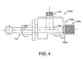
- FIGURES 4 and 5 illustrate an embodiment wherein the housing 106a and an end 108a of the expandable member 102a are molded together;
- FIGURE 6 illustrates an embodiment wherein the expandable member 102b is snapped onto the housing 106b using a snap ring 110;
- FIGURE 13 illustrates an embodiment wherein the expandable member 102c is glued or otherwise affixed to an external surface 112 of the housing 106c. Regardless of how the expandable member 102a, 102b, 102c is secured to the housing 106a, 106b, 106c, the fact that an expandable member is utilized in the design provides that different ranges of retraction can be accommodated in a single, compact design.
- each of the headlamp adjusters preferably includes a housing, an output adjuster shaft 104 which extends from the housing and is engageable with a headlamp reflector (see FIGURE 1), a rotatable input member 120, gearing 122 in the housing which provides that rotation of the rotatable input member 120 causes extension and retraction of the adjuster output shaft 104 (depending on which direction the rotatable input member 120 is rotated), and structure 124 such as a seated nut (see FIGURES 5, 6, 9 and 13) for providing that the adjuster output shaft 104 translates when it rotates rather than just rotates.
- each of the headlamp adjusters are preferably provided consistent with that which is shown in Figures 12-15 of U.S. Patent No. 6,450,674 and described therein, except that each of the embodiments of the present invention preferably includes an expandable member at the rear end of the housing, instead of a non-expandable tower as disclosed in the '674 patent.
- U.S. Patent No. 6,450,674 is hereby incorporated herein by reference in its entirety.
- each of the embodiments of the present invention which is disclosed herein includes an expandable member 102a, 102b, 102c which is disposed proximate the rear end of the housing 106a, 106b, 106c. More specifically, preferably the expandable member 102a, 102b, 102c is provided in the form of an expandable bellow or accordion member, which may be formed of an elastomeric, moldable material, such as rubber or a synthetic form thereof.
- FIGURES 4 and 5 illustrate an embodiment wherein the housing 106a and an end 108a of the expandable member 102a are molded together.
- such an embodiment may be formed using a plastic injection molding process wherein a material such as rubber, plastic, or some other suitable material, such as an elastomeric material, is injected into a mold cavity where the mold cavity is shaped like the resulting expandable member. Then, the expandable member 102a is ejected from the mold and inserted into a mold cavity which has a portion which is generally shaped like the housing 106a. Then, plastic is injected into the mold cavity, and the plastic allowed to cool. Finally, the resulting part is ejected from the mold cavity.
- This method provides that the housing 106a is molded over the expandable member 102a, such as is shown in FIGURES 4 and 5.
- the expandable member 102a can be molded over the end of the housing 106a.
- the housing 106a is molded first in a plastic injection molding process, and then is ejected and placed in a second mold cavity which includes a portion which corresponds to the expandable member. Then, rubber, plastic or some other suitable material, such as an elastomeric material, is injected into the mold cavity to form the expandable member over the end of the housing. Finally, the part is ejected.
- FIGURE 6 illustrates an alternative embodiment wherein the expandable member 102b is engaged with the housing 106b viz-a-viz a snap fit using a snap ring 110 which is configured to hold a front end 108b of the expandable member 102b and slide into a slot 150 which is provided on the rear end of the housing 106b, thereby securing the expandable member 102b to the housing 106b.
- the expandable member 102b and snap ring 110 are shown isolated in FIGURE 7.
- the preferred shape of the rear end of the housing 106b can best be seen in FIGURES 8 and 9, and the preferred shape of the snap ring 110 can best be seen in FIGURES 10-12.
- the snap ring includes finger grip 162 portions for deforming the snap ring 110 to engage the snap ring 110 with the slot 150 provided in the housing 106b.
- FIGURE 13 illustrates yet another embodiment of the present invention.
- the expandable member 102c is adhered to an external surface 112 of the housing 106c using a suitable adhesive.
Landscapes
- Engineering & Computer Science (AREA)
- Mechanical Engineering (AREA)
- Non-Portable Lighting Devices Or Systems Thereof (AREA)
- Lighting Device Outwards From Vehicle And Optical Signal (AREA)
- Sealing Devices (AREA)
Abstract
Description
Claims (18)
- A headlamp adjuster (100a, 100b, 100c) for adjusting a position of a reflector (24) of a headlamp assembly (12), said headlamp adjuster (100a, 100b, 100c) characterized by: a housing (106a, 106b, 106c); an expandable member (102a, 102b, 102c) on the housing (106a, 106b, 106c); an adjuster member (104) having a first end and a second end, said adjuster member (104) being extendable and retractable, wherein said first end of said adjuster member (104) is engageable with the reflector (24) of the headlamp assembly (12), and said second end of said adjuster member (104) is receivable in the expandable member (102a, 102b, 102c), wherein said expandable member (102a, 102b, 102c) is configured to expand to accommodate retraction of the adjuster member (104).
- A headlamp adjuster (100a, 100b, 100c) as recited in claim 1, characterized in that said expandable member (102a, 102b, 102c) comprises a bellows.
- A headlamp adjuster (100a, 100b, 100c) as recited in claim 2, characterized in that said bellows is comprised of rubber.
- A headlamp adjuster (100a, 100b, 100c) as recited in claim 2, characterized in that said bellows is comprised of rubber and said housing (106a, 106b, 106c) is comprised of plastic.
- A headlamp adjuster (100a) as recited in claim 2, characterized in that said housing (106a) and said bellows are molded together.
- A headlamp adjuster (100a) as recited in claim 2, characterized in that said housing (106a) is molded over said bellows.
- A headlamp adjuster (100c) as recited in claim 2, characterized in that said bellows is glued to said housing (106c).
- A headlamp adjuster (100b) as recited in claim 2, characterized by a snap ring (110) which secures said bellows to said housing (106b).
- A headlamp adjuster (100a, 100b, 100c) as recited in claim 1, characterized in that said headlamp adjuster (100a, 100b, 100c) is configured such that said second end of said adjuster member (104) is engageable and pressable against an internal wall (132a, 132b, 132c) of said expandable member (102a, 102b, 102c), thereby causing said expandable member (102a, 102b, 102c) to expand.
- A headlamp adjuster (100a, 100b, 100c) as recited in claim 1, characterized in that said expandable member (102a, 102b, 102c) comprises an accordion member.
- A method of adjusting a position of a reflector (24) of a headlamp assembly (12), said method characterized by: retracting an adjuster member (104) of a headlamp adjuster (100a, 100b, 100c); and using an expandable member (102a, 102b, 102c) of the headlamp adjuster (100a, 100b, 100c) to receive an end (108a, 108b, 108c) of the adjuster member (104) as the adjuster member (104) retracts and expands to accommodate retraction of the adjuster member (104).
- A method as recited in claim 11, characterized in that the step of using an expandable member (102a, 102b, 102c) comprises using a bellows.
- A method as recited in claim 11, characterized in that the step of using an expandable member (102a, 102b, 102c) comprises using a bellows formed of at least one of rubber, plastic, an elastomeric material and a synthetic material.
- A method as recited in claim 12, characterized in that a housing (106a) of said headlamp adjuster (100a) is molded over said bellows.
- A method as recited in claim 11, characterized in that the step of using an expandable member (102c) comprises using a bellows which is glued to a housing (106c) of said headlamp adjuster (100c).
- A method as recited in claim 11, characterized in that the step of using an expandable member (102b) comprises using a bellows which is secured to a housing (106b) of said headlamp adjuster (100b) with a snap ring (110).
- A method as recited in claim 11, characterized by pressing an end of said adjuster member against an internal wall (132a, 132b, 132c) of said expandable member (102a, 102b, 102c), thereby causing said expandable member (102a, 102b, 102c) to expand.
- A method as recited in claim 11, characterized in that the step of using an expandable member (102a, 102b, 102c) comprises using an accordion member.
Applications Claiming Priority (2)
| Application Number | Priority Date | Filing Date | Title |
|---|---|---|---|
| US10/689,481 US7090384B2 (en) | 2003-10-20 | 2003-10-20 | Headlamp adjuster with expandable member for accommodating retraction of an adjuster output member |
| US689481 | 2003-10-20 |
Publications (2)
| Publication Number | Publication Date |
|---|---|
| EP1526037A2 true EP1526037A2 (en) | 2005-04-27 |
| EP1526037A3 EP1526037A3 (en) | 2006-05-03 |
Family
ID=34394520
Family Applications (1)
| Application Number | Title | Priority Date | Filing Date |
|---|---|---|---|
| EP04254436A Withdrawn EP1526037A3 (en) | 2003-10-20 | 2004-07-23 | Headlamp adjuster with expandable member for accommodating retraction of an adjuster output member |
Country Status (2)
| Country | Link |
|---|---|
| US (1) | US7090384B2 (en) |
| EP (1) | EP1526037A3 (en) |
Cited By (1)
| Publication number | Priority date | Publication date | Assignee | Title |
|---|---|---|---|---|
| FR2978394A1 (en) * | 2011-07-28 | 2013-02-01 | Valeo Vision | Assembly for projector used for projection of light beam on road followed by car, has mechanical connection formed between adjustment unit and support of optical module, where connection includes damping unit for damping vibrations |
Families Citing this family (3)
| Publication number | Priority date | Publication date | Assignee | Title |
|---|---|---|---|---|
| DE102006008363A1 (en) * | 2006-02-21 | 2007-08-30 | Schefenacker Vision Systems Germany Gmbh | Adjustment system for headlights |
| US7637685B2 (en) * | 2006-10-13 | 2009-12-29 | Valeo Sylvania Llc | Retention member for ball socket joint |
| US9157594B2 (en) * | 2012-12-20 | 2015-10-13 | Hella Kgaa Hueck & Co. | Adjusting device for headlights |
Family Cites Families (26)
| Publication number | Priority date | Publication date | Assignee | Title |
|---|---|---|---|---|
| FR2664963B1 (en) | 1990-07-23 | 1992-11-13 | Valeo Vision | PROJECTOR COMPRISING MEANS FOR ADJUSTING BEAM ORIENTATION. |
| US5186532A (en) | 1991-05-07 | 1993-02-16 | Textron Inc. | Headlamp adjusting mechanism and headlamp adjusting assembly |
| US5193905A (en) | 1991-12-13 | 1993-03-16 | Elco Industries, Inc. | Vehicle headlamp adjuster |
| US5285360A (en) | 1991-12-16 | 1994-02-08 | Textron Inc. | Automotive headlamp adjuster |
| CA2088139C (en) | 1992-03-19 | 2002-10-08 | Ronald S. Denley | Level indicating device for a vehicle headlamp |
| US5309780A (en) | 1992-10-15 | 1994-05-10 | Textron Inc. | Torque limiting headlamp adjustor |
| US5390089A (en) | 1993-06-01 | 1995-02-14 | Elco Industries, Inc. | Dual coordinate headlamp adjuster |
| US5359499A (en) | 1993-11-18 | 1994-10-25 | Elco Industries, Inc. | Vertical/horizontal indicator for a vehicular headlamp |
| US5398173A (en) | 1994-01-24 | 1995-03-14 | Elco Industries, Inc. | Headlamp adjuster with stamped gear |
| US5355287A (en) | 1994-03-10 | 1994-10-11 | Elco Industries, Inc. | Headlamp adjuster with sealed adjusting link |
| US5414937A (en) | 1994-03-14 | 1995-05-16 | Elco Industries, Inc. | Headlamp indicating device with highlighted level bubble |
| US5544023A (en) | 1994-07-11 | 1996-08-06 | Textron Inc. | Horizontal zero indicator assembly |
| US5642935A (en) | 1995-07-31 | 1997-07-01 | Textron Inc. | Headlamp adjustor with vent tube |
| US5775794A (en) | 1995-07-31 | 1998-07-07 | Textron Inc. | Headlamp adjustor with vent tube |
| US5539625A (en) | 1995-08-31 | 1996-07-23 | General Motors Corporation | Vehicle headlamp aiming device |
| DE19648050B4 (en) * | 1995-11-28 | 2006-03-09 | Honda Giken Kogyo K.K. | Hydraulic pressure source device and vehicle height control device |
| US5752321A (en) | 1996-05-08 | 1998-05-19 | Textron Inc. | Headlamp position indicator device |
| US5673992A (en) | 1996-05-29 | 1997-10-07 | Textron Inc. | Sealing device for a headlamp adjustor mechanism |
| US5746000A (en) | 1996-08-14 | 1998-05-05 | Textron Inc. | Headlamp assembly with magnetic indicator for horizontal and vertical positioning |
| US6338567B1 (en) | 1999-03-04 | 2002-01-15 | Elco Textron Inc. | Gearless headlamp adjustor |
| US6450674B2 (en) | 1999-12-03 | 2002-09-17 | Elco Textron Inc. | Headlamp adjuster configured to prevent over-travel of an adjuster output shaft |
| US6447154B1 (en) | 1999-12-03 | 2002-09-10 | Elco Textron Inc. | Headlamp adjuster with overload clutch mechanism |
| US6568837B2 (en) | 2000-04-21 | 2003-05-27 | Elco Textron Inc. | Motorized headlamp adjuster |
| KR100410696B1 (en) * | 2000-11-02 | 2003-12-18 | 현대자동차주식회사 | Mounting structure of head lamp for automobile |
| US6779835B2 (en) * | 2001-12-06 | 2004-08-24 | Lear Corporation | Energy absorbing structure for automobile interior |
| DE20216836U1 (en) * | 2002-10-31 | 2003-02-06 | Böllhoff GmbH, 33649 Bielefeld | Plug-in coupling with three-dimensional compensation movement |
-
2003
- 2003-10-20 US US10/689,481 patent/US7090384B2/en not_active Expired - Fee Related
-
2004
- 2004-07-23 EP EP04254436A patent/EP1526037A3/en not_active Withdrawn
Cited By (1)
| Publication number | Priority date | Publication date | Assignee | Title |
|---|---|---|---|---|
| FR2978394A1 (en) * | 2011-07-28 | 2013-02-01 | Valeo Vision | Assembly for projector used for projection of light beam on road followed by car, has mechanical connection formed between adjustment unit and support of optical module, where connection includes damping unit for damping vibrations |
Also Published As
| Publication number | Publication date |
|---|---|
| US20050083709A1 (en) | 2005-04-21 |
| EP1526037A3 (en) | 2006-05-03 |
| US7090384B2 (en) | 2006-08-15 |
Similar Documents
| Publication | Publication Date | Title |
|---|---|---|
| US6746142B2 (en) | Headlamp for automobile with aiming screw having locking portion | |
| JPH0917210A (en) | Optical axis adjusting structure for vehicle lamp and assembly method thereof | |
| JP3074557B2 (en) | Vehicle headlamp | |
| US5851082A (en) | Axial ball-and-socket joint for linkages in motor vehicles | |
| US20140153268A1 (en) | Gear screw adjuster | |
| KR100389784B1 (en) | Vehicle lamp | |
| IT1235165B (en) | FASTENING AND JOINTING BODY, IN PARTICULAR FOR A VEHICLE HEADLIGHT | |
| JP2006131022A (en) | Lighting fixture for vehicle | |
| US6315439B1 (en) | Headlamp adjustor and method | |
| EP1526037A2 (en) | Headlamp adjuster with expandable member for accommodating retraction of an adjuster output member | |
| CN111565973B (en) | Mounting module for a vehicle lamp | |
| JP5430225B2 (en) | Vehicle lighting | |
| US6450674B2 (en) | Headlamp adjuster configured to prevent over-travel of an adjuster output shaft | |
| US7198392B2 (en) | Torque limiting adjuster | |
| US6568837B2 (en) | Motorized headlamp adjuster | |
| US7303321B2 (en) | Temporary assembly clip for snap-fit gear boxes | |
| US6796693B2 (en) | 180-degree adjuster | |
| US20040151005A1 (en) | Headlight for motor vehicles | |
| US5615939A (en) | Headlight of a self-propelled vehicle, especially for a motor vehicle | |
| CN218626638U (en) | Coupling assembling, mechanism and car light adjust luminance | |
| US6447154B1 (en) | Headlamp adjuster with overload clutch mechanism | |
| US7572042B2 (en) | Leveling device for vehicular headlamp | |
| EP0933253A2 (en) | A device for positioning and securing a headlamp on a support structure of a vehicle | |
| CN1152685A (en) | Ventilation systemf or lamp and shade tube thereof | |
| JP3104845B2 (en) | Vehicle lighting |
Legal Events
| Date | Code | Title | Description |
|---|---|---|---|
| PUAI | Public reference made under article 153(3) epc to a published international application that has entered the european phase |
Free format text: ORIGINAL CODE: 0009012 |
|
| AK | Designated contracting states |
Kind code of ref document: A2 Designated state(s): AT BE BG CH CY CZ DE DK EE ES FI FR GB GR HU IE IT LI LU MC NL PL PT RO SE SI SK TR |
|
| AX | Request for extension of the european patent |
Extension state: AL HR LT LV MK |
|
| PUAL | Search report despatched |
Free format text: ORIGINAL CODE: 0009013 |
|
| AK | Designated contracting states |
Kind code of ref document: A3 Designated state(s): AT BE BG CH CY CZ DE DK EE ES FI FR GB GR HU IE IT LI LU MC NL PL PT RO SE SI SK TR |
|
| AX | Request for extension of the european patent |
Extension state: AL HR LT LV MK |
|
| RIC1 | Information provided on ipc code assigned before grant |
Ipc: F21V 14/04 20060101ALI20060310BHEP Ipc: B60Q 1/068 20060101AFI20050211BHEP |
|
| AKX | Designation fees paid | ||
| REG | Reference to a national code |
Ref country code: DE Ref legal event code: 8566 |
|
| STAA | Information on the status of an ep patent application or granted ep patent |
Free format text: STATUS: THE APPLICATION IS DEEMED TO BE WITHDRAWN |
|
| 18D | Application deemed to be withdrawn |
Effective date: 20061104 |