EP1524760B1 - Electronic device for controlling a discharge pump driven by a synchronous electric motor with a permanent-magnet rotor - Google Patents
Electronic device for controlling a discharge pump driven by a synchronous electric motor with a permanent-magnet rotor Download PDFInfo
- Publication number
- EP1524760B1 EP1524760B1 EP03425653A EP03425653A EP1524760B1 EP 1524760 B1 EP1524760 B1 EP 1524760B1 EP 03425653 A EP03425653 A EP 03425653A EP 03425653 A EP03425653 A EP 03425653A EP 1524760 B1 EP1524760 B1 EP 1524760B1
- Authority
- EP
- European Patent Office
- Prior art keywords
- motor
- current
- electronic device
- discharge pump
- pump
- Prior art date
- Legal status (The legal status is an assumption and is not a legal conclusion. Google has not performed a legal analysis and makes no representation as to the accuracy of the status listed.)
- Expired - Lifetime
Links
- 230000001360 synchronised effect Effects 0.000 title claims abstract description 16
- 238000004804 winding Methods 0.000 claims description 8
- 230000002457 bidirectional effect Effects 0.000 claims description 4
- 230000010363 phase shift Effects 0.000 abstract description 14
- XLYOFNOQVPJJNP-UHFFFAOYSA-N water Substances O XLYOFNOQVPJJNP-UHFFFAOYSA-N 0.000 description 8
- 238000010586 diagram Methods 0.000 description 7
- 230000001276 controlling effect Effects 0.000 description 6
- 238000005406 washing Methods 0.000 description 3
- 230000005355 Hall effect Effects 0.000 description 2
- 239000012530 fluid Substances 0.000 description 2
- 239000007788 liquid Substances 0.000 description 2
- 239000000203 mixture Substances 0.000 description 2
- 230000001105 regulatory effect Effects 0.000 description 2
- 239000000126 substance Substances 0.000 description 2
- 239000003570 air Substances 0.000 description 1
- 230000002547 anomalous effect Effects 0.000 description 1
- 238000012790 confirmation Methods 0.000 description 1
- 230000003111 delayed effect Effects 0.000 description 1
- 238000007599 discharging Methods 0.000 description 1
- 238000004851 dishwashing Methods 0.000 description 1
- 230000004907 flux Effects 0.000 description 1
- 239000004088 foaming agent Substances 0.000 description 1
- 238000010438 heat treatment Methods 0.000 description 1
- 238000004519 manufacturing process Methods 0.000 description 1
- 238000012986 modification Methods 0.000 description 1
- 230000004048 modification Effects 0.000 description 1
- 238000013021 overheating Methods 0.000 description 1
- 230000001012 protector Effects 0.000 description 1
- 230000000630 rising effect Effects 0.000 description 1
- 230000003068 static effect Effects 0.000 description 1
Images


Classifications
-
- H—ELECTRICITY
- H02—GENERATION; CONVERSION OR DISTRIBUTION OF ELECTRIC POWER
- H02P—CONTROL OR REGULATION OF ELECTRIC MOTORS, ELECTRIC GENERATORS OR DYNAMO-ELECTRIC CONVERTERS; CONTROLLING TRANSFORMERS, REACTORS OR CHOKE COILS
- H02P27/00—Arrangements or methods for the control of AC motors characterised by the kind of supply voltage
- H02P27/02—Arrangements or methods for the control of AC motors characterised by the kind of supply voltage using supply voltage with constant frequency and variable amplitude
-
- F—MECHANICAL ENGINEERING; LIGHTING; HEATING; WEAPONS; BLASTING
- F04—POSITIVE - DISPLACEMENT MACHINES FOR LIQUIDS; PUMPS FOR LIQUIDS OR ELASTIC FLUIDS
- F04D—NON-POSITIVE-DISPLACEMENT PUMPS
- F04D15/00—Control, e.g. regulation, of pumps, pumping installations or systems
- F04D15/0066—Control, e.g. regulation, of pumps, pumping installations or systems by changing the speed, e.g. of the driving engine
-
- H—ELECTRICITY
- H02—GENERATION; CONVERSION OR DISTRIBUTION OF ELECTRIC POWER
- H02P—CONTROL OR REGULATION OF ELECTRIC MOTORS, ELECTRIC GENERATORS OR DYNAMO-ELECTRIC CONVERTERS; CONTROLLING TRANSFORMERS, REACTORS OR CHOKE COILS
- H02P25/00—Arrangements or methods for the control of AC motors characterised by the kind of AC motor or by structural details
- H02P25/02—Arrangements or methods for the control of AC motors characterised by the kind of AC motor or by structural details characterised by the kind of motor
- H02P25/022—Synchronous motors
- H02P25/024—Synchronous motors controlled by supply frequency
Definitions
- the present invention relates, in its more general aspect, to a synchronous discharge pump, i.e. a pump driven by a synchronous electric motor with a permanent-magnet rotor, particularly of the type incorporated in a household appliance.
- this invention relates to an electronic device for controlling said pump and of the type comprising at least a controller receiving at its input a synchronizing signal of the motor supply voltage and at least a second signal being proportional to the current absorbed by the motor, to drive at its output a switch being series-connected to one of the motor windings.
- discharge pumps are operated for a predetermined time, discharging liquids as well as air and foaming agents.
- the discharge pump can operate sucking an air-water mixture.
- the electronic control device interrupts the pump operation (i.e. it interrupts the synchronous electric motor operation) for a certain time.
- the interruption period is predetermined and it depends on the household appliance wherein the pump is used.
- the interruption can last even a few seconds, after which the pump is restarted assuming that, in the meantime, a valuable amount of liquid has been accumulated, which is sufficient to avoid the partial-load operation, which is noisy and also unstable.
- the electronic control device is capable of recognising the air-water operating state and, consequently, it is capable of interrupting the pump operation.
- Figure 1 schematically shows a first embodiment of an electronic device of the known type showing how the synchronous motor starting step is regulated according to a network synchronizing signal and a signal provided by a Hall-effect rotor position sensor.
- an electronic control device receives at its input a signal 4 coming from a rotor position sensor 2 of the motor 3, and a network synchronizing signal 5.
- the controller 1 drives a static power switch 6, for example a TRIAC being series-connected to one of the stator windings.
- the position sensor 2 which in the case of a permanent-magnet synchronous motor can be very conveniently a Hall-effect sensor, provides an angle coinciding, except for a constant, with the load angle ⁇ .
- the passage of the rotor magnetic flux peak can be measured. Knowing that the latter is delayed by 90° with respect to the counter electromotive force, the load angle ⁇ can be precisely determined as phase shift between the voltage applied to the motor 3 terminals. This voltage is known by means of the network synchronizing signal 5.
- the phase shift ⁇ is thus determined by the controller 1 taking as reference the network synchronizing signal 5 which is a square wave signal, with rising and falling edges coinciding with the supply voltage zero-crossing.
- Figures 2 and 3 show two vector diagrams of the voltage V, of the current I and of the counter electromotive force E, related to two different operating conditions wherein the load angle ⁇ is different.
- Figure 2 schematically shows a vector diagram allowing a better understanding of the calculations performed in the controller 1
- X indicates the stator winding inductance
- R is the resistance of these windings
- I is the supply current
- V is the supply voltage
- ⁇ is the load angle
- ⁇ is the phase shift between the supply voltage and the current
- Eo is the counter electromotive force.
- Figure 3 shows the same diagram but related to a different operating condition with a different load angle.
- the different operating modes to be identified are very distinct; for example, regular full load operation and air-water operation, to be thus able to turn the pump off in the latter case to avoid useless noises.
- phase shift between the Sync signal 5 and a Current signal 7, conveniently adopted and squared off, is measured by means of a sensor 8.
- controller 1 Being it possible to equip the controller 1 with logic and/or calculation means, it is not very expensive to compare the measuring stability of said phase shift in a convenient time period, a stable full load pump operation index, with a possible instability, a certain air-water pump operation index.
- the pump operates in a silent way and with full load and it is turned off when a certain amount of air is accumulated in the pump coil; after a certain time, when the water amount is sufficient to discharge in a stable and silent way, the pump is restarted.
- the problem underlying the present invention is to provide an discharge pump for controlling a synchronous motor, particularly for household appliances, having such structural and functional features as to allow all the drawbacks mentioned with reference to the prior art to be overcome in a simple and unexpensive way.
- a discharge pump comprising an electronic control device and driven by a synchronous motor with a permanent magnet rotor defined in claim 1 and the followings.
- an electronic device manufactured in accordance with the present invention for controlling a discharge pump 15 driven by a permanent-magnet synchronous electric motor 3 and incorporated in a household appliance is described in detail and globally indicated with 10.
- the device 10 conventionally comprises at least a controller 1 receiving at its input a synchronizing signal 5 of the supply network voltage V of the motor 3 and at least a second signal 7 being proportional to the current absorbed by the motor, to drive at its output a switch 6 being series-connected to one of the motor windings.
- the switch 6 is manufactured with a bidirectional switch, particularly a device 11 comprising a four-diode bridge.
- the Triac 6 is replaced by a bidirectional switch, for example an SCR device as central element of a power-diode bridge.
- the SCR device 11 has advantageously an overall cost being lower or equal to another kind of switch, but it also offers the possibility of having a univocal and clear current zero crossing signal, thus avoiding complex and/or highly amplified signal regulation blocks, which are then more delicate from the point of view of noises, as in prior art devices.
- Vd is the drop by direct conduction of one of the bridge diodes and Vscr is the drop by SCR direct conduction.
- the diagrams of figures 8 and 9 show the graphs of the quantities network Voltage, Current and corresponding values SYNC (squared network voltage) and Current (just described Va - Vb).
- the amplitudes of these signals can be directly processed by low voltage logics being available on the market (1.8 V).
- the square wave value of the Current signal 7 with positive sense current can be greater by adding in series a convenient resistance or another junction, according to the needs.
- the main advantage achieved by the electronic device according to the present invention is its unusual simplicity, reliability and extremely low cost.
- the switch 11 is not a Triac and then the application must not undergo a failure test of the "diode mode" type.
- the device 11 is suitable for being monolithically manufactured together with the controller 1 as integrated circuit with control pins directly connecting to the motor. In this case short-circuit or open-circuit failure tests could be performed; both situations would not be however dangerous since the motor would run or would be blocked according to the case, without power crossing.
- the thermal protection could be even removed if also the "blocked rotor" failure test could be controlled: in this case the controller 1 can detect the rotor blocked through the phase shift between voltage and current, then through the anomalous phase shift between the SYNC and Current signals 5 and 7, with blocked rotor.
- the controller 1 could acquire the dangerous state and stop the supply.
- a housing and supplying board 18 of the device 11 can be provided in a recess formed between two motor windings.
- the thermal sensor could be housed on the opposite side with respect to the device 11, ensuring however a sufficient pump thermal protection.
- controller 1 is an arithmetical-logic integrated circuit, it is also possible to exploit the calculation capability thereof to perform redundant controls to ensure the operating safety.
- the electronic device 10 for controlling a synchronous discharge pump as previously described can undergo some modifications, all within the reach of the skilled in the art and falling within the scope of protection of the present invention, as defined in the following claims.
Abstract
Description
- The present invention relates, in its more general aspect, to a synchronous discharge pump, i.e. a pump driven by a synchronous electric motor with a permanent-magnet rotor, particularly of the type incorporated in a household appliance.
- In particular, this invention relates to an electronic device for controlling said pump and of the type comprising at least a controller receiving at its input a synchronizing signal of the motor supply voltage and at least a second signal being proportional to the current absorbed by the motor, to drive at its output a switch being series-connected to one of the motor windings.
- It is well known that some household appliances, such as washing machines and dish-washing machines, are provided with pumps serving to discharge outwards fluids comprising water and washing residuals.
- These fluids are not accumulated in a constant and predictable way according to washing programs; consequently, it often happens that discharge pumps are operated for a predetermined time, discharging liquids as well as air and foaming agents. In substance, the discharge pump can operate sucking an air-water mixture.
- During the time period wherein this kind of operation occurs, the noise produced by the pump considerably increases.
- To try and remedy this drawback, the prior art suggests to apply electronic control circuits to the pumps capable of regulating the operation thereof in critical conditions.
- In practise, as soon as an operating state with air-water mixture sucking occurs, the electronic control device interrupts the pump operation (i.e. it interrupts the synchronous electric motor operation) for a certain time. The interruption period is predetermined and it depends on the household appliance wherein the pump is used.
- The interruption can last even a few seconds, after which the pump is restarted assuming that, in the meantime, a valuable amount of liquid has been accumulated, which is sufficient to avoid the partial-load operation, which is noisy and also unstable.
- There are different operating modes depending on the kind of household appliance. In any case, the electronic control device is capable of recognising the air-water operating state and, consequently, it is capable of interrupting the pump operation.
-
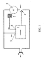
Figure 1 schematically shows a first embodiment of an electronic device of the known type showing how the synchronous motor starting step is regulated according to a network synchronizing signal and a signal provided by a Hall-effect rotor position sensor. - As shown in
figure 1 , an electronic control device,controller 1, receives at its input asignal 4 coming from arotor position sensor 2 of themotor 3, and anetwork synchronizing signal 5. Thecontroller 1 drives astatic power switch 6, for example a TRIAC being series-connected to one of the stator windings. - As it is known, the
position sensor 2, which in the case of a permanent-magnet synchronous motor can be very conveniently a Hall-effect sensor, provides an angle coinciding, except for a constant, with the load angle ∂. - For example, with a
digital Hall sensor 2, the passage of the rotor magnetic flux peak can be measured. Knowing that the latter is delayed by 90° with respect to the counter electromotive force, the load angle ∂ can be precisely determined as phase shift between the voltage applied to themotor 3 terminals. This voltage is known by means of thenetwork synchronizing signal 5. - The phase shift ∂ is thus determined by the
controller 1 taking as reference thenetwork synchronizing signal 5 which is a square wave signal, with rising and falling edges coinciding with the supply voltage zero-crossing. -
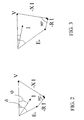
Figures 2 and 3 show two vector diagrams of the voltage V, of the current I and of the counter electromotive force E, related to two different operating conditions wherein the load angle ∂ is different. -
Figure 2 schematically shows a vector diagram allowing a better understanding of the calculations performed in thecontroller 1 - X indicates the stator winding inductance;
- R is the resistance of these windings;
- I is the supply current;
- V is the supply voltage;
- ∂ is the load angle;
- ϕ is the phase shift between the supply voltage and the current;
- Eo is the counter electromotive force.
-
Figure 3 shows the same diagram but related to a different operating condition with a different load angle. - In practise, with the electronic device of
figure 1 , it is easy to detect the air-water operation, since the load angle ∂ considerably varies with respect to the normal operation. - The different operating modes to be identified are very distinct; for example, regular full load operation and air-water operation, to be thus able to turn the pump off in the latter case to avoid useless noises.
- During these two different operations, even in various voltage and prevalence conditions, very different load angles ∂ are obtained, explaining more reasonable, but however significant, variations of the phase shift angle between the voltage and the current ϕ, as shown in the diagrams of
figures 2 and 3 . - On the basis of the previous considerations, it is possible to prepare an electronic device being arranged only for reading the phase shift between the voltage and the current, as schematically shown in
figure 4 . - After all, the phase shift between the
Sync signal 5 and a Current signal 7, conveniently adopted and squared off, is measured by means of asensor 8. - Being it possible to equip the
controller 1 with logic and/or calculation means, it is not very expensive to compare the measuring stability of said phase shift in a convenient time period, a stable full load pump operation index, with a possible instability, a certain air-water pump operation index. - A further possibility thus results, which can also be used to obtain a confirmation, of identifying the difference between the two states concerned, allowing the desired operating mode to be reached. The pump operates in a silent way and with full load and it is turned off when a certain amount of air is accumulated in the pump coil; after a certain time, when the water amount is sufficient to discharge in a stable and silent way, the pump is restarted.
- Although advantageous under different points of view, the previously described electronic circuits have some drawbacks; for example they are delicate from the point of view of noises, since they provide complex and/or highly amplified signal regulation blocks.
- Moreover, the urgent demand for cost reduction imposes the use of simple and non very expensive components however capable to ensure operation reliability and a long pump service life.
- In this context it is worth noting that when the pump is driven by a Triac, see for example
EP-A-0574823 , also an expensive thermal protection of the pump itself must be provided, because of the rigorous reliability tests undergone by the pump. In fact Triacs undergo failure tests of the "diode mode" type keeping the rotor blocked and these operating conditions leave motors windings live with subsequent pump overheating and permanent damage risk. - The problem underlying the present invention is to provide an discharge pump for controlling a synchronous motor, particularly for household appliances, having such structural and functional features as to allow all the drawbacks mentioned with reference to the prior art to be overcome in a simple and unexpensive way.
- The technical problem is solved by a discharge pump comprising an electronic control device and driven by a synchronous motor with a permanent magnet rotor defined in
claim 1 and the followings. - The other features and the advantages of the synchronous discharge pump will be more apparent from the description of an embodiment thereof, given hereafter with reference to the attached drawings given by way of indicative and non-limiting example.
-
-
Figure 1 schematically shows a first embodiment of electronic device for controlling a discharge pump, driven by a permanent-magnet synchronous electric motor and used in a household appliance, according to the prior art; -
Figures 2 and 3 schematically show two vector diagrams of the voltage V, of the current I absorbed by the motor in two different operating conditions, i.e. two diagrams with different load angle and subsequently different phase shift; -
Figure 4 schematically shows a second embodiment of electronic control device, according to the prior art. -
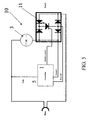
Figure 5 schematically shows an electronic device for controlling a discharge pump, driven by a permanent-magnet synchronous electric motor and used in a household appliance, according to the present invention. -
Figures 6 and7 define the operating logic of the electronic device offigure 5 . -
Figures 8 and9 show graphs processed by the electronic device offigure 5 ; -
Figure 10 is a perspective schematic view of a discharge pump incorporating an electronic control device according to the invention. - With particular reference to
figures 5 to 10 , an electronic device manufactured in accordance with the present invention for controlling adischarge pump 15 driven by a permanent-magnet synchronouselectric motor 3 and incorporated in a household appliance (not shown in the figures) is described in detail and globally indicated with 10. - As previously seen, with reference to the prior art, the
device 10 conventionally comprises at least acontroller 1 receiving at its input a synchronizingsignal 5 of the supply network voltage V of themotor 3 and at least a second signal 7 being proportional to the current absorbed by the motor, to drive at its output aswitch 6 being series-connected to one of the motor windings. - Advantageously according to the present invention the
switch 6 is manufactured with a bidirectional switch, particularly adevice 11 comprising a four-diode bridge. - In substance, the Triac 6 is replaced by a bidirectional switch, for example an SCR device as central element of a power-diode bridge.
- The apparent greater complexity is rewarded by the lower gate current required by the
SCR device 11 switching. This is an important advantage for the cheapest auxiliary supply. - The
SCR device 11 has advantageously an overall cost being lower or equal to another kind of switch, but it also offers the possibility of having a univocal and clear current zero crossing signal, thus avoiding complex and/or highly amplified signal regulation blocks, which are then more delicate from the point of view of noises, as in prior art devices. - It is worth noting that two different circuits according to the current sense participate in
device 11. - This distinctive feature will now be described in greater detail.
- By examining, thanks to
figure 6 , the voltage signal Va with respect to the voltage signal Vb, as shown in bothfigures 6 and7 , two operating situations with two very different voltages occur. - With positive current (
figure 6 )
- Where Vd is the drop by direct conduction of one of the bridge diodes and Vscr is the drop by SCR direct conduction.
- Values of about 1.3/2 V are obtained, according to the components being used.
- With negative current (
figure 7 )
- And a value of about - 0.6/1 V is obtained
- The diagrams of
figures 8 and9 show the graphs of the quantities network Voltage, Current and corresponding values SYNC (squared network voltage) and Current (just described Va - Vb). - As it can be noted, they are univocal signals being perfectly in phase with the quantities they refer to and wherefrom the phase angle ϕ between the supply voltage V and the current I can be easily calculated.
- The amplitudes of these signals can be directly processed by low voltage logics being available on the market (1.8 V).
- The square wave value of the Current signal 7 with positive sense current can be greater by adding in series a convenient resistance or another junction, according to the needs.
- This variation does not invalidate the Current value with negative sense current.
- The main advantage achieved by the electronic device according to the present invention is its unusual simplicity, reliability and extremely low cost.
- The
switch 11 is not a Triac and then the application must not undergo a failure test of the "diode mode" type. - If however the "diode mode" test would have to be performed, it would not cause dangerous operating conditions just because of the presence of
device 11; because the motor would keep running since both half waves would be provided and no particular heating condition would occur. - Moreover, the
device 11 is suitable for being monolithically manufactured together with thecontroller 1 as integrated circuit with control pins directly connecting to the motor. In this case short-circuit or open-circuit failure tests could be performed; both situations would not be however dangerous since the motor would run or would be blocked according to the case, without power crossing. - With such a solution it is possible to manufacture, complying with the rules, a pump without thermal protector, i.e. examining, if necessary, a failure at a time.
- The thermal protection could be even removed if also the "blocked rotor" failure test could be controlled: in this case the
controller 1 can detect the rotor blocked through the phase shift between voltage and current, then through the anomalous phase shift between the SYNC andCurrent signals 5 and 7, with blocked rotor. - However, according to the needs, it is possible to provide a thermal protection also for the device according to the invention. For example, if for some applications the phase shift would be similar to normal operating conditions, by means of a simple low-cost thermal sensor, optionally mounted on the
same housing board 18 of the SCR device, thecontroller 1 could acquire the dangerous state and stop the supply. - For example, as shown in
figure 10 , a housing and supplyingboard 18 of thedevice 11 can be provided in a recess formed between two motor windings. On thisboard 18 the thermal sensor could be housed on the opposite side with respect to thedevice 11, ensuring however a sufficient pump thermal protection. - Since the
controller 1 is an arithmetical-logic integrated circuit, it is also possible to exploit the calculation capability thereof to perform redundant controls to ensure the operating safety. - The
electronic device 10 for controlling a synchronous discharge pump as previously described can undergo some modifications, all within the reach of the skilled in the art and falling within the scope of protection of the present invention, as defined in the following claims.
Claims (3)
- A discharge pump driven by a synchronous electric motor with a permanent-magnet rotor (3) and comprising a control electronic device (10) for interrupting the pump operation and comprising at least a controller (1) receiving at its input a synchronizing signal (5) of the motor supply voltage (V) and at least a second signal (7) being proportional to the current absorbed by the motor, to drive at its output a switch (6) being series-connected to one of the motor windings, said switch being a bidirectional switch (11), characterised in that said bidirectional switch comprises an SCR (11) being the central element of a four power-diode bridge.
- A discharge pump according to claim 1, characterised in that said control electronic device (10) is manufactured in a monolithically integrated way.
- A discharge pump according to claim 1, characterised in that it is associated with a thermal sensor mounted on a housing board (18) of the device (10).
Priority Applications (9)
| Application Number | Priority Date | Filing Date | Title |
|---|---|---|---|
| ES03425653T ES2378661T3 (en) | 2003-10-07 | 2003-10-07 | Electronic device for controlling a discharge pump driven by a synchronous electric motor with a permanent magnet rotor |
| EP05023243A EP1638201B1 (en) | 2003-10-07 | 2003-10-07 | Method for controlling and driving a pump for household appliances |
| AT05023243T ATE428216T1 (en) | 2003-10-07 | 2003-10-07 | ELECTRONIC DEVICE FOR CONTROLLING A DISCHARGE PUMP BY A SYNCHRONOUS MOTOR WITH PERMANENT MAGNET ROTOR |
| DE60327111T DE60327111D1 (en) | 2003-10-07 | 2003-10-07 | Electronic device for controlling a discharge pump by a synchronous motor with permanent magnet rotor |
| EP03425653A EP1524760B1 (en) | 2003-10-07 | 2003-10-07 | Electronic device for controlling a discharge pump driven by a synchronous electric motor with a permanent-magnet rotor |
| AT03425653T ATE536478T1 (en) | 2003-10-07 | 2003-10-07 | ELECTRONIC DEVICE FOR CONTROLLING A DISCHARGE PUMP BY A SYNCHRONOUS MOTOR WITH PERMANENT MAGNET ROTOR |
| DE20321134U DE20321134U1 (en) | 2003-10-07 | 2003-10-07 | Electronic device for controlling and driving a pump for household appliances |
| ES05023243T ES2324997T3 (en) | 2003-10-07 | 2003-10-07 | METHOD TO CONTROL AND OPERATE A PUMP FOR APPLIANCES. |
| US10/959,761 US7068008B2 (en) | 2003-10-07 | 2004-10-06 | Electronic device for controlling a discharge pump driven by a synchronous electric motor with a permanent-magnet rotor |
Applications Claiming Priority (1)
| Application Number | Priority Date | Filing Date | Title |
|---|---|---|---|
| EP03425653A EP1524760B1 (en) | 2003-10-07 | 2003-10-07 | Electronic device for controlling a discharge pump driven by a synchronous electric motor with a permanent-magnet rotor |
Related Child Applications (2)
| Application Number | Title | Priority Date | Filing Date |
|---|---|---|---|
| EP05023243A Division EP1638201B1 (en) | 2003-10-07 | 2003-10-07 | Method for controlling and driving a pump for household appliances |
| EP05023243.8 Division-Into | 2005-10-25 |
Publications (2)
| Publication Number | Publication Date |
|---|---|
| EP1524760A1 EP1524760A1 (en) | 2005-04-20 |
| EP1524760B1 true EP1524760B1 (en) | 2011-12-07 |
Family
ID=34354642
Family Applications (2)
| Application Number | Title | Priority Date | Filing Date |
|---|---|---|---|
| EP03425653A Expired - Lifetime EP1524760B1 (en) | 2003-10-07 | 2003-10-07 | Electronic device for controlling a discharge pump driven by a synchronous electric motor with a permanent-magnet rotor |
| EP05023243A Expired - Lifetime EP1638201B1 (en) | 2003-10-07 | 2003-10-07 | Method for controlling and driving a pump for household appliances |
Family Applications After (1)
| Application Number | Title | Priority Date | Filing Date |
|---|---|---|---|
| EP05023243A Expired - Lifetime EP1638201B1 (en) | 2003-10-07 | 2003-10-07 | Method for controlling and driving a pump for household appliances |
Country Status (5)
| Country | Link |
|---|---|
| US (1) | US7068008B2 (en) |
| EP (2) | EP1524760B1 (en) |
| AT (2) | ATE428216T1 (en) |
| DE (2) | DE20321134U1 (en) |
| ES (2) | ES2378661T3 (en) |
Families Citing this family (9)
| Publication number | Priority date | Publication date | Assignee | Title |
|---|---|---|---|---|
| WO2007053042A2 (en) * | 2005-11-04 | 2007-05-10 | Fisher & Paykel Appliances Limited | Washing machine pump control for water drainage, ventilation, dislodging blockage and recirculation |
| DE102008029910C5 (en) * | 2008-06-24 | 2020-03-05 | BSH Hausgeräte GmbH | Method for recognizing the load status of a pump |
| EP2428608B1 (en) * | 2010-09-14 | 2012-12-19 | Miele & Cie. KG | Method for operating a pump in a washing machine, mechatronic system and washing machine |
| DE102010042494A1 (en) * | 2010-10-15 | 2012-04-19 | BSH Bosch und Siemens Hausgeräte GmbH | Method for shutdown of discharge pump of washing machine, involves determining parameter that is correlated with rotational torque of motor to shutdown motor when predetermined criterion is met in relation to parameter |
| ITTO20110413A1 (en) * | 2011-05-11 | 2012-11-12 | Amc S N C Di Ruscello Lorenzo & C | CIRCUIT ARRANGEMENT FOR THE DETECTION OF THE LOAD APPLIED TO AN ELECTRIC MOTOR ON THE BASIS OF THE DISASTER ANGLE BETWEEN THE ELECTRIC SIZES OF THE MOTOR |
| US20160301349A1 (en) * | 2013-11-29 | 2016-10-13 | Arcelik Anonim Sirketi | Household appliance with multiple synchronous motors and control circuit thereof |
| DE102014103472A1 (en) | 2014-03-14 | 2015-09-17 | Miele & Cie. Kg | Pumping device for a water-conducting device and water-conducting device |
| CN107482760B (en) * | 2016-06-08 | 2020-06-30 | 光宝电子(广州)有限公司 | Switching device |
| RU2687175C1 (en) * | 2018-06-18 | 2019-05-07 | федеральное государственное автономное образовательное учреждение высшего образования "Южно-Уральский государственный университет (национальный исследовательский университет)" | Control system of electric drive of pump unit and method of operation of system |
Citations (4)
| Publication number | Priority date | Publication date | Assignee | Title |
|---|---|---|---|---|
| CH524709A (en) * | 1971-03-02 | 1972-06-30 | Holzer Patent Ag | Arrangement with a control circuit, a motor and an additional electrical heating resistor |
| EP0629037A1 (en) * | 1993-06-08 | 1994-12-14 | POMPES SALMSON Société Anonyme à directoire dite: | Power supply control process and device for an electric asynchronous motor |
| WO1998059174A1 (en) * | 1997-06-20 | 1998-12-30 | Arçelik A.S. | Electronic control method for drain pumps used in electrical home appliances |
| EP0948126A2 (en) * | 1998-04-04 | 1999-10-06 | Grundfos A/S | Device for detecting parameter of an asynchronous motor |
Family Cites Families (8)
| Publication number | Priority date | Publication date | Assignee | Title |
|---|---|---|---|---|
| US3908158A (en) * | 1973-05-09 | 1975-09-23 | Borg Warner | Control system for adjusting a-c motor speed at line frequency or a subharmonic of the line frequency |
| US4806838A (en) * | 1988-05-23 | 1989-02-21 | Weber Harold J | A.C. induction motor energy conserving power control method and apparatus |
| IT1259115B (en) * | 1992-06-17 | 1996-03-11 | Askoll Spa | ELECTRONIC DEVICE FOR STARTING A SYNCHRONOUS MOTOR WITH PERMANENT MAGNET ROTOR |
| JP3555297B2 (en) * | 1996-02-06 | 2004-08-18 | 松下電器産業株式会社 | Power generator and vacuum cleaner as its application equipment |
| JP2001078446A (en) * | 1999-06-29 | 2001-03-23 | Toshiba Corp | Power supply unit |
| DE10014665B4 (en) * | 2000-03-24 | 2005-09-22 | Siemens Ag | Method for protecting a matrix converter from overvoltages and an active overvoltage device |
| DE10014641C2 (en) * | 2000-03-24 | 2002-03-07 | Siemens Ag | Circuit arrangement with a bidirectional circuit breaker in common collector mode and with an active overvoltage protection device |
| GB2396441B (en) * | 2002-12-20 | 2005-11-30 | Motorola Inc | Circuit and method for supplying an electrical a.c. load |
-
2003
- 2003-10-07 AT AT05023243T patent/ATE428216T1/en not_active IP Right Cessation
- 2003-10-07 DE DE20321134U patent/DE20321134U1/en not_active Expired - Lifetime
- 2003-10-07 ES ES03425653T patent/ES2378661T3/en not_active Expired - Lifetime
- 2003-10-07 EP EP03425653A patent/EP1524760B1/en not_active Expired - Lifetime
- 2003-10-07 AT AT03425653T patent/ATE536478T1/en active
- 2003-10-07 DE DE60327111T patent/DE60327111D1/en not_active Expired - Lifetime
- 2003-10-07 ES ES05023243T patent/ES2324997T3/en not_active Expired - Lifetime
- 2003-10-07 EP EP05023243A patent/EP1638201B1/en not_active Expired - Lifetime
-
2004
- 2004-10-06 US US10/959,761 patent/US7068008B2/en active Active
Patent Citations (4)
| Publication number | Priority date | Publication date | Assignee | Title |
|---|---|---|---|---|
| CH524709A (en) * | 1971-03-02 | 1972-06-30 | Holzer Patent Ag | Arrangement with a control circuit, a motor and an additional electrical heating resistor |
| EP0629037A1 (en) * | 1993-06-08 | 1994-12-14 | POMPES SALMSON Société Anonyme à directoire dite: | Power supply control process and device for an electric asynchronous motor |
| WO1998059174A1 (en) * | 1997-06-20 | 1998-12-30 | Arçelik A.S. | Electronic control method for drain pumps used in electrical home appliances |
| EP0948126A2 (en) * | 1998-04-04 | 1999-10-06 | Grundfos A/S | Device for detecting parameter of an asynchronous motor |
Also Published As
| Publication number | Publication date |
|---|---|
| DE60327111D1 (en) | 2009-05-20 |
| ATE536478T1 (en) | 2011-12-15 |
| EP1638201B1 (en) | 2009-04-08 |
| ATE428216T1 (en) | 2009-04-15 |
| EP1524760A1 (en) | 2005-04-20 |
| EP1638201A2 (en) | 2006-03-22 |
| EP1638201A3 (en) | 2006-05-31 |
| DE20321134U1 (en) | 2006-08-03 |
| US7068008B2 (en) | 2006-06-27 |
| US20050073278A1 (en) | 2005-04-07 |
| ES2324997T3 (en) | 2009-08-21 |
| ES2378661T3 (en) | 2012-04-16 |
Similar Documents
| Publication | Publication Date | Title |
|---|---|---|
| KR0140353B1 (en) | Drive apparatus for brushless dc motor and failure diagnosing method for the same | |
| CN101258673B (en) | A method for controlling a mechanically commutated electric motor | |
| US8497654B2 (en) | Single phase AC synchronized motor | |
| CN102769428A (en) | Motor control apparatus with insulation degradation detection device and insulation degradation detection method of motor | |
| EP1524760B1 (en) | Electronic device for controlling a discharge pump driven by a synchronous electric motor with a permanent-magnet rotor | |
| CN101174804A (en) | Electric start controlling equipment for synchronous motor | |
| US8872457B2 (en) | Method and apparatus for driving a polyphase electronically commutated electric machine and a motor system | |
| US11664750B2 (en) | Multispeed alternating current motor | |
| JP2007085337A (en) | Vacuum pump device | |
| US7675256B2 (en) | Controller for DC brushless motor integrated with a high voltage control system | |
| JP2007318824A (en) | Driving device for motor-driven compressor | |
| US20100201303A1 (en) | System for Controlling the Steady-State Rotation of a Synchronous Electric Motor | |
| JP4539237B2 (en) | Inverter device | |
| KR100558996B1 (en) | Electric washing machine | |
| JP4788603B2 (en) | Inverter device | |
| CN107809192B (en) | Motor drive device, motor assembly, and load drive device | |
| KR101665891B1 (en) | Apparatus for sensing disorder of transistor driving motor | |
| JP5228387B2 (en) | Inverter device | |
| KR101039435B1 (en) | Apparatus and method for controlling motor | |
| KR100936019B1 (en) | Driving apparatus and method for motor of treadmill | |
| JP4884434B2 (en) | Electric motor drive | |
| CN209462288U (en) | A kind of brushless motor control circuit of no Hall element | |
| JP4186791B2 (en) | Starter generator for internal combustion engines | |
| CN111082713A (en) | Brushless Hall-free direct current motor driver | |
| KR20170017818A (en) | Magnetic sensor, integrated circuit and motor assembly |
Legal Events
| Date | Code | Title | Description |
|---|---|---|---|
| PUAI | Public reference made under article 153(3) epc to a published international application that has entered the european phase |
Free format text: ORIGINAL CODE: 0009012 |
|
| AK | Designated contracting states |
Kind code of ref document: A1 Designated state(s): AT BE BG CH CY CZ DE DK EE ES FI FR GB GR HU IE IT LI LU MC NL PT RO SE SI SK TR |
|
| AX | Request for extension of the european patent |
Extension state: AL LT LV MK |
|
| 17P | Request for examination filed |
Effective date: 20051018 |
|
| AKX | Designation fees paid |
Designated state(s): AT BE BG CH CY CZ DE DK EE ES FI FR GB GR HU IE IT LI LU MC NL PT RO SE SI SK TR |
|
| 17Q | First examination report despatched |
Effective date: 20061204 |
|
| REG | Reference to a national code |
Ref country code: DE Ref legal event code: R079 Ref document number: 60339326 Country of ref document: DE Free format text: PREVIOUS MAIN CLASS: H02P0007622000 Ipc: F04D0013060000 |
|
| RIC1 | Information provided on ipc code assigned before grant |
Ipc: F04D 15/02 20060101ALI20110411BHEP Ipc: F04D 13/06 20060101AFI20110411BHEP |
|
| GRAP | Despatch of communication of intention to grant a patent |
Free format text: ORIGINAL CODE: EPIDOSNIGR1 |
|
| GRAS | Grant fee paid |
Free format text: ORIGINAL CODE: EPIDOSNIGR3 |
|
| GRAA | (expected) grant |
Free format text: ORIGINAL CODE: 0009210 |
|
| AK | Designated contracting states |
Kind code of ref document: B1 Designated state(s): AT BE BG CH CY CZ DE DK EE ES FI FR GB GR HU IE IT LI LU MC NL PT RO SE SI SK TR |
|
| REG | Reference to a national code |
Ref country code: GB Ref legal event code: FG4D |
|
| REG | Reference to a national code |
Ref country code: CH Ref legal event code: EP |
|
| REG | Reference to a national code |
Ref country code: DE Ref legal event code: R082 Ref document number: 60339326 Country of ref document: DE Representative=s name: HUBER & SCHUESSLER, DE |
|
| REG | Reference to a national code |
Ref country code: IE Ref legal event code: FG4D |
|
| REG | Reference to a national code |
Ref country code: DE Ref legal event code: R096 Ref document number: 60339326 Country of ref document: DE Effective date: 20120216 |
|
| REG | Reference to a national code |
Ref country code: NL Ref legal event code: VDEP Effective date: 20111207 |
|
| REG | Reference to a national code |
Ref country code: ES Ref legal event code: FG2A Ref document number: 2378661 Country of ref document: ES Kind code of ref document: T3 Effective date: 20120416 |
|
| PG25 | Lapsed in a contracting state [announced via postgrant information from national office to epo] |
Ref country code: GR Free format text: LAPSE BECAUSE OF FAILURE TO SUBMIT A TRANSLATION OF THE DESCRIPTION OR TO PAY THE FEE WITHIN THE PRESCRIBED TIME-LIMIT Effective date: 20120308 Ref country code: NL Free format text: LAPSE BECAUSE OF FAILURE TO SUBMIT A TRANSLATION OF THE DESCRIPTION OR TO PAY THE FEE WITHIN THE PRESCRIBED TIME-LIMIT Effective date: 20111207 Ref country code: SI Free format text: LAPSE BECAUSE OF FAILURE TO SUBMIT A TRANSLATION OF THE DESCRIPTION OR TO PAY THE FEE WITHIN THE PRESCRIBED TIME-LIMIT Effective date: 20111207 Ref country code: SE Free format text: LAPSE BECAUSE OF FAILURE TO SUBMIT A TRANSLATION OF THE DESCRIPTION OR TO PAY THE FEE WITHIN THE PRESCRIBED TIME-LIMIT Effective date: 20111207 |
|
| PG25 | Lapsed in a contracting state [announced via postgrant information from national office to epo] |
Ref country code: BE Free format text: LAPSE BECAUSE OF FAILURE TO SUBMIT A TRANSLATION OF THE DESCRIPTION OR TO PAY THE FEE WITHIN THE PRESCRIBED TIME-LIMIT Effective date: 20111207 Ref country code: CY Free format text: LAPSE BECAUSE OF FAILURE TO SUBMIT A TRANSLATION OF THE DESCRIPTION OR TO PAY THE FEE WITHIN THE PRESCRIBED TIME-LIMIT Effective date: 20111207 |
|
| PG25 | Lapsed in a contracting state [announced via postgrant information from national office to epo] |
Ref country code: CZ Free format text: LAPSE BECAUSE OF FAILURE TO SUBMIT A TRANSLATION OF THE DESCRIPTION OR TO PAY THE FEE WITHIN THE PRESCRIBED TIME-LIMIT Effective date: 20111207 Ref country code: BG Free format text: LAPSE BECAUSE OF FAILURE TO SUBMIT A TRANSLATION OF THE DESCRIPTION OR TO PAY THE FEE WITHIN THE PRESCRIBED TIME-LIMIT Effective date: 20120307 Ref country code: EE Free format text: LAPSE BECAUSE OF FAILURE TO SUBMIT A TRANSLATION OF THE DESCRIPTION OR TO PAY THE FEE WITHIN THE PRESCRIBED TIME-LIMIT Effective date: 20111207 |
|
| REG | Reference to a national code |
Ref country code: SK Ref legal event code: T3 Ref document number: E 11744 Country of ref document: SK |
|
| PG25 | Lapsed in a contracting state [announced via postgrant information from national office to epo] |
Ref country code: RO Free format text: LAPSE BECAUSE OF FAILURE TO SUBMIT A TRANSLATION OF THE DESCRIPTION OR TO PAY THE FEE WITHIN THE PRESCRIBED TIME-LIMIT Effective date: 20111207 Ref country code: PT Free format text: LAPSE BECAUSE OF FAILURE TO SUBMIT A TRANSLATION OF THE DESCRIPTION OR TO PAY THE FEE WITHIN THE PRESCRIBED TIME-LIMIT Effective date: 20120409 |
|
| REG | Reference to a national code |
Ref country code: AT Ref legal event code: MK05 Ref document number: 536478 Country of ref document: AT Kind code of ref document: T Effective date: 20111207 |
|
| PLBE | No opposition filed within time limit |
Free format text: ORIGINAL CODE: 0009261 |
|
| STAA | Information on the status of an ep patent application or granted ep patent |
Free format text: STATUS: NO OPPOSITION FILED WITHIN TIME LIMIT |
|
| PG25 | Lapsed in a contracting state [announced via postgrant information from national office to epo] |
Ref country code: DK Free format text: LAPSE BECAUSE OF FAILURE TO SUBMIT A TRANSLATION OF THE DESCRIPTION OR TO PAY THE FEE WITHIN THE PRESCRIBED TIME-LIMIT Effective date: 20111207 |
|
| 26N | No opposition filed |
Effective date: 20120910 |
|
| REG | Reference to a national code |
Ref country code: DE Ref legal event code: R097 Ref document number: 60339326 Country of ref document: DE Effective date: 20120910 |
|
| PG25 | Lapsed in a contracting state [announced via postgrant information from national office to epo] |
Ref country code: AT Free format text: LAPSE BECAUSE OF FAILURE TO SUBMIT A TRANSLATION OF THE DESCRIPTION OR TO PAY THE FEE WITHIN THE PRESCRIBED TIME-LIMIT Effective date: 20111207 |
|
| PG25 | Lapsed in a contracting state [announced via postgrant information from national office to epo] |
Ref country code: MC Free format text: LAPSE BECAUSE OF NON-PAYMENT OF DUE FEES Effective date: 20121031 |
|
| REG | Reference to a national code |
Ref country code: CH Ref legal event code: PL |
|
| GBPC | Gb: european patent ceased through non-payment of renewal fee |
Effective date: 20121007 |
|
| PG25 | Lapsed in a contracting state [announced via postgrant information from national office to epo] |
Ref country code: FI Free format text: LAPSE BECAUSE OF FAILURE TO SUBMIT A TRANSLATION OF THE DESCRIPTION OR TO PAY THE FEE WITHIN THE PRESCRIBED TIME-LIMIT Effective date: 20111207 |
|
| REG | Reference to a national code |
Ref country code: IE Ref legal event code: MM4A |
|
| PG25 | Lapsed in a contracting state [announced via postgrant information from national office to epo] |
Ref country code: GB Free format text: LAPSE BECAUSE OF NON-PAYMENT OF DUE FEES Effective date: 20121007 Ref country code: IE Free format text: LAPSE BECAUSE OF NON-PAYMENT OF DUE FEES Effective date: 20121007 Ref country code: LI Free format text: LAPSE BECAUSE OF NON-PAYMENT OF DUE FEES Effective date: 20121031 Ref country code: CH Free format text: LAPSE BECAUSE OF NON-PAYMENT OF DUE FEES Effective date: 20121031 |
|
| PG25 | Lapsed in a contracting state [announced via postgrant information from national office to epo] |
Ref country code: LU Free format text: LAPSE BECAUSE OF NON-PAYMENT OF DUE FEES Effective date: 20121007 |
|
| PG25 | Lapsed in a contracting state [announced via postgrant information from national office to epo] |
Ref country code: HU Free format text: LAPSE BECAUSE OF FAILURE TO SUBMIT A TRANSLATION OF THE DESCRIPTION OR TO PAY THE FEE WITHIN THE PRESCRIBED TIME-LIMIT Effective date: 20031007 |
|
| REG | Reference to a national code |
Ref country code: FR Ref legal event code: PLFP Year of fee payment: 14 |
|
| REG | Reference to a national code |
Ref country code: FR Ref legal event code: PLFP Year of fee payment: 15 |
|
| REG | Reference to a national code |
Ref country code: FR Ref legal event code: PLFP Year of fee payment: 16 |
|
| PGFP | Annual fee paid to national office [announced via postgrant information from national office to epo] |
Ref country code: TR Payment date: 20220926 Year of fee payment: 20 Ref country code: SK Payment date: 20220922 Year of fee payment: 20 |
|
| PGFP | Annual fee paid to national office [announced via postgrant information from national office to epo] |
Ref country code: FR Payment date: 20220921 Year of fee payment: 20 |
|
| PGFP | Annual fee paid to national office [announced via postgrant information from national office to epo] |
Ref country code: IT Payment date: 20220920 Year of fee payment: 20 Ref country code: ES Payment date: 20221102 Year of fee payment: 20 Ref country code: DE Payment date: 20220920 Year of fee payment: 20 |
|
| REG | Reference to a national code |
Ref country code: DE Ref legal event code: R071 Ref document number: 60339326 Country of ref document: DE |
|
| REG | Reference to a national code |
Ref country code: SK Ref legal event code: MK4A Ref document number: E 11744 Country of ref document: SK Expiry date: 20231007 |
|
| REG | Reference to a national code |
Ref country code: ES Ref legal event code: FD2A Effective date: 20231026 |
|
| PG25 | Lapsed in a contracting state [announced via postgrant information from national office to epo] |
Ref country code: SK Free format text: LAPSE BECAUSE OF EXPIRATION OF PROTECTION Effective date: 20231007 |
|
| PG25 | Lapsed in a contracting state [announced via postgrant information from national office to epo] |
Ref country code: ES Free format text: LAPSE BECAUSE OF EXPIRATION OF PROTECTION Effective date: 20231008 |
|
| PG25 | Lapsed in a contracting state [announced via postgrant information from national office to epo] |
Ref country code: SK Free format text: LAPSE BECAUSE OF EXPIRATION OF PROTECTION Effective date: 20231007 Ref country code: ES Free format text: LAPSE BECAUSE OF EXPIRATION OF PROTECTION Effective date: 20231008 |