BACKGROUND OF THE INVENTION
1. Field of the Invention
-
The present invention relates to an image forming apparatus which
adjusts image forming conditions based on a detected density of a patch
image, and a control method for such an image forming apparatus.
2. Description of the Related Art
-
An image forming apparatus such as a printer, a copier machine
and a facsimile machine utilizing electrophotographic technology, when
needed, forms a small test image (patch image) having a predetermined
image pattern, detects the image density of this image with a density
sensor, and adjusts operation conditions of the respective portions of the
apparatus (image forming conditions) in accordance with the result of the
detection, so that a desired image quality is achieved stably.
-
For instance, in the case of the image forming apparatus described
in Japanese Patent Application Laid-Open Gazette No. 2001-75318,
warming up of the apparatus is executed immediately after the apparatus
has been turned on or immediately after the apparatus has been released
from a sleep mode. As this completes, density adjusting processing is
carried out. During the density adjusting processing, optimal values of a
charging bias and a developing bias, which serve as density control factors
which influence the qualities of images, are calculated based on a detected
density of a solid or halftone image formed as a patch image. With the
charging bias and the developing bias set respectively to thus calculated
optimal values, optimal image forming conditions are attained. As an
image forming operation is executed under the image forming conditions
optimized in this manner, an image is formed in a favorable and stable
image quality.
-
Among image forming apparatuses of this type is such an image
forming apparatus which outputs, when necessary, a status sheet for the
purpose of notifying a user, an operator or someone who otherwise uses
the apparatus of the state of the apparatus. The status sheet describes
operation parameters for the respective portions of the apparatus, the result
of self-diagnosis and the like,
-
When an operator so wishes, it is desirable that these apparatuses
will skip the density adjusting processing. These are when the first print
time needs be shortened or when a reduction of the amount of toner
demanded by the density adjusting processing is desired, for instance. In
the event that an image consisting only of letters, characters, lines and the
like or a monochrome image is to be formed, precise density adjusting
processing is not always necessary. Besides, there may be an instance
that a status sheet mentioned above is wanted for the purpose of
maintenance of an apparatus. However, the conventional image forming
apparatus described above does not meet these demands.
SUMMARY OF THE INVENTION
-
An object of the present invention is to provide a control technique
which makes it possible to flexibly respond to an operator's demand when
applied to an image forming apparatus which adjusts an image forming
condition based on a detected density of a patch image and a control
method for such an image forming apparatus.
-
To achieve this object, in an image forming apparatus which
executes control processing which is for adjustment of image forming
conditions, which are to be used during execution of an image forming
operation by an image forming section, to predetermined optimal
conditions based on a detected density of a patch image formed by the
image forming section and in a control method for such an image forming
apparatus, when a setting section is operated in a setting operation which
prohibits the control processing, the image forming section is permitted
execution of the image forming operation while skipping the control
processing, according to the present invention.
-
In other aspect of the present invention, to achieve the object above,
in an image forming apparatus which executes control processing which is
for adjustment of image forming conditions, which are to be used during
execution of an image forming operation by an image forming section, to
predetermined optimal conditions based on a detected density of a patch
image formed by an image forming section and in a control method for
such an image forming apparatus, a setting state of a setting section is
judged in accordance with a predetermined operation and the control
processing is executed when the setting state is not in a prohibition state
which is for the prohibition of the control processing, and when the setting
state is in the prohibition state, the image forming section is permitted
execution of the image forming operation while skipping the control
processing.
-
In these inventions, the image forming operation is executed
normally under the image forming conditions which have been adjusted to
the optimal conditions as a result of the control processing. Hence, a user
can stably obtain images in a constant image quality. However, when the
user operates the setting section in the setting operation so as to prohibit
execution of the control processing, execution of the image forming
operation is permitted while skipping the control processing. These
inventions thus make it possible to flexibly respond to various demands
from users.
-
The above and further objects and novel features of the invention
will more fully appear from the following detailed description when the
same is read in connection with the accompanying drawing. It is to be
expressly understood, however, that the drawing is for purpose of
illustration only and is not intended as a definition of the limits of the
invention.
BRIEF DESCRIPTION OF THE DRAWINGS
-
- Fig. 1 is a diagram showing a preferred embodiment of an image
forming apparatus according to the present invention;
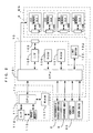
- Fig. 2 is a block diagram which shows an electric structure of the
apparatus of Fig. 1;
- Fig. 3 is an external appearance view of the image forming
apparatus of Fig. 1;
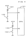
- Fig. 4 is a drawing which shows connection between the limit
switches and the CPU;
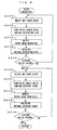
- Fig. 5 is a flow chart of the start-up processing in this apparatus;
- Fig. 6 is a flow chart of the patch processing performed by this
apparatus; and
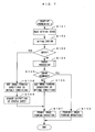
- Fig. 7 is a flow chart of the start-up processing performed in this
apparatus according to a different aspect.
-
DETAILED DESCRIPTION OF THE PREFERRED EMBODIMENTS
-
Fig. 1 is a diagram showing a preferred embodiment of an image
forming apparatus according to the present invention. Fig. 2 is a block
diagram which shows an electric structure of the apparatus of Fig. 1.
This apparatus is an image forming apparatus for forming a full color
image by superimposing images of toners of four colors: yellow (Y), cyan
(C), magenta (M) and black (K) and forming a monochromatic image only
using the black (K) toner. In this image forming apparatus, when a print
command signal including an image signal is given from an external
apparatus such as a host computer to a main controller 11, an engine
controller 10 controls individual parts of an engine section EG for
executing a specified image forming operation in accordance with a
command from the main controller 11, whereby an image corresponding to
the image signal is formed on a sheet S.
-
In this engine section EG, a photosensitive member 22 is rotatably
provided in a direction of arrow D1 of Fig. 1. Further, a charger unit 23,
a rotary developing unit 4 and a cleaning section 25 are arranged around
the photosensitive member 22 along its rotating direction D1. A specified
charging bias is applied to the charger unit 23 to uniformly charge the
outer circumferential surface of the photosensitive member 22 at a
specified surface potential. The cleaning section 25 removes the toner
residual on the outer surface of the photosensitive member 22 after a
primary transfer and collects it in a waste toner tank provided therein.
The photosensitive member 22, the charger unit 23 and the cleaning
section 25 are incorporated into a photosensitive-member cartridge 2,
which is detachably mountable into the apparatus main body 1 as a single
unit.
-
A light beam L is emitted from an exposure unit 6 toward the outer
circumferential surface of the photosensitive member 22 charged by the
charger unit 23. This exposure unit 6 exposes the photosensitive member
22 by the light beam L in accordance with the image signal given from the
external apparatus to form an electrostatic latent image corresponding to
the image signal.
-
The thus formed electrostatic latent image is developed into a toner
image by the rotary developing unit 4. Specifically, the developing unit 4
includes: a supporting frame 40 rotatably provided about a rotary shaft; a
developer for yellow 4Y; a developer for cyan 4C; a developer for magenta
4M;a developer for black 4K; and a rotary driving device (not shown).
The four developing units 4Y, 4C, 4M and 4K contain the toners of the
respective colors and are constructed as cartridges detachably mountable
into the supporting frame 40. This developing unit 4 is controlled by the
CPU 160. The developing unit 4 is rotated in accordance with a control
command from the CPU 101. When the developers 4Y, 4C, 4M, 4K
thereof are selectively brought into contact with the photosensitive
member 22 or positioned at a specified developing position facing the
photosensitive member 22 at a specified gap, the toner is imparted from a
developing roller 44 provided in this developer and carrying the toner of
the selected color to the outer surface of the photosensitive member 22.
In this way, the electrostatic latent image on the photosensitive member 22
is developed in the selected toner color.
-
The toner image developed by the developing unit 4 as described
above undergoes a primary transfer onto an intermediate transfer belt 71 of
a transfer unit 7 in a primary transfer region TR1. The transfer unit 7
includes the intermediate transfer belt 71 mounted on a plurality of rollers
72 to 75 and a driving device (not shown) for driving the roller 73 to turn
the intermediate transfer belt 71 in a specified turning direction D2. In
the case of transferring a color image onto the sheet S, the toner images of
the respective colors formed on the photosensitive member 22 are
superimposed on the intermediate transfer belt 71 to form the color image,
which then undergoes a second transfer onto the sheet S dispensed one by
one from a cassette 8 and conveyed to a secondary transfer region TR2
along a conveyance path F.
-
At this time, a timing at which the sheet S is fed to the secondary
transfer region TR2 is controlled in order to properly transfer the image on
the intermediate transfer belt 71 to a specified position on the sheet S.
Specifically, gate rollers 81 are provided before the second transfer region
TR2 in the conveyance path F, and the sheet S is fed to the secondary
transfer region TR2 at a specified timing by rotating the gate rollers 81 in
conformity with a turning timing of the intermediate transfer belt 71.
-
The sheet S having the color image thus formed thereon is
conveyed to be discharged onto a discharge tray 89 provided on the upper
surface of the apparatus main body 1 via a fixing unit 9, pre-discharge
rollers 82 and discharge rollers 83. Further, in the case of forming images
on both surfaces of the sheet S, the rotating directions of the discharging
rollers 83 are reversed when the trailing end of the sheet S having the
image formed on one surface thereof as described above reaches a
reversing position PR behind the pre-discharge rollers 82, whereby the
sheet S is conveyed in a direction of arrow D3 along a reversing
conveyance path FR. Then, the sheet S enters the conveyance path F
again before the gate rollers 81. At this time, the surface of the sheet S to
be brought into contact with the intermediate transfer belt 71 in the
secondary transfer region TR2 to have an image transferred thereto is the
surface opposite from the one where the image was already transferred.
In this way, the images can be formed on both surfaces of the sheet S.
-
In addition, a density sensor 60 is disposed in the vicinity of the
roller 75. The density sensor 60 confronts the surface of the intermediate
transfer belt 71 and operates, as required, to take measurement of an image
density of the toner image formed on the outside surface of the
intermediate transfer belt 71. Based on the measurement results, the
apparatus 1 adjusts the operating conditions of the individual parts of the
apparatus which may affect image quality. The operating conditions
include, for example, a developing bias applied to each of the developer,
an intensity the exposure light beam L, tone correction characteristics of
the apparatus and the like.
-
The density sensor 60 employs, for example, a reflective
photosensor and is designed to output a signal corresponding to an image
density of a region of a given area defined on the intermediate transfer belt
71. With the intermediate transfer belt 71 held in cycling motion, the
CPU 101 periodically samples the output signal from the density sensor 60,
thereby detecting an image density of an individual part of the toner image
on the intermediate transfer belt 71.
As shown in Fig. 2, nonvolatile memories 91 through 94 are disposed onto
the developers 4Y, 4C, 4M, 4K, respectively. These nonvolatile
memories 91 through 94 are adapted to save information on the production
lots, the used states, physical quantities representing the state and the like
of the developer. Furthermore, the developers 4Y, 4C, 4M, 4K include
connectors 49Y, 49C, 49M, 49K, respectively. When needed, the
connectors 49Y, 49C, 49M, 49K are selectively brought into contact with a
connector 109 of the apparatus main body. Accordingly, the CPU 101
and the memory 91 through 94 can exchange data via the interface 105,
whereby the administration of the informations regarding the consumable
supplies are carried out. In this embodiment, the developer side
connector 49Y, 49C, 49M, 49K is mechanically connected with the main-body
side connector 109 to carry out the reading and writing from and in
the memory 91 through 94. However, the reading and writing may be
carried out in a noncontacting manner using an electromagnetic means
such as a radio communication using, for example, infrared rays.
-
In Fig.2, a reference numeral 113 represents an image memory
provided in the main controller 11 in order to store the image supplied
from the external apparatus, such as a host computer, via an interface 112.
A reference numeral 106 represents a ROM for storage of an operation
program executed by the CPU 101 and control data used for controlling the
engine section EG. A reference numeral 107 represents a RAM for
temporary storage of operation results given by the CPU 101 and other
data.
-
To save information related to the states of use of the respective
portions of the apparatus, it is preferable to use non-volatile memories
which save information even when not energized as these RAMs 107, 117
and 91 through 94. As such elements, flash memories, ferroelectric
memories or the like may be used.
-
In addition, limit switches 122 and 132 for sensing whether a cover
disposed to the housing of the apparatus is open or close are connected to a
CPU 101 of this apparatus 1. These will be described in detail later.
-
Fig. 3 is an external appearance view of the image forming
apparatus shown in Fig. 1. As described earlier, developers 4Y, ... are
freely attachable to and detachable from a support frame 40 in the image
forming apparatus 1. Further, a photosensitive cartridge 2 is freely
attachable to and detachable from the main body of the apparatus. As
shown in Fig. 3, an external cover 120 which can be opened and closed
freely is attached to a side surface portion of the main body of the
apparatus 1. When a user opens the external cover 120, a side surface
portion of the photosensitive cartridge 2 is exposed through a
photosensitive opening 125 which is formed in the main body of the
apparatus. As a lock lever 126 for fixing the photosensitive cartridge 2 is
revolved in the direction of the arrow D4, the lock is released, making it
possible to pull out the photosensitive cartridge 2 along the direction of the
axis (-y) in Fig. 3. Further, when a new photosensitive cartridge 2 is
inserted along the direction of the axis y shown in Fig. 3 through the
photosensitive opening 125, the new photosensitive cartridge 2 is attached.
The photosensitive cartridge 2 is then fixed with the lock lever 125. As
the photosensitive cartridge 2 is attached in this fashion, the side surface
portion of the photosensitive cartridge 2 almost completely closes the
photosensitive opening 125.
-
In addition, the main body of the apparatus has a developer
opening 135 which is for attaching and detaching the photosensitive
cartridge. An internal cover 130 which can be opened and closed freely is
disposed as if to cover the developer opening 135. The internal cover 130
is disposed inside the external cover 120. In short, since the external
cover 120 is disposed covering the developer opening 135, the internal
cover 130 cannot be opened when the external cover 120 is closed.
Conversely, unless the internal cover 130 is closed, the external cover 120
cannot be closed. When a user opens the internal cover 130, as long as a
developer unit 4 is in a halt at a predetermined attaching/detaching position,
it is possible to take out one of the attached developers through the
developer opening 135. Further, at this stage, it is possible to attach one
developer through the developer opening 135.
-
While a projection 121a is formed in the external cover 120, the
main body has a hole 121b located at a position corresponding to the
projection 121a. Further, the limit switch 122 which will be described
later is attached to a bottom portion of the hole 121b. When the external
cover 120 is closed, the projection 121a is inserted in the hole 121b which
is formed in the main body, and the contact of the limit switch 122
disposed to the bottom portion of the hole 121b is closed.
-
The internal cover 130 comprises a similar mechanism to this.
That is, while a projection 131a is disposed to the internal cover 130, the
main body has a hole 131b located at a position corresponding to the
projection 131a. As the internal cover 130 is closed, the projection 131a
is inserted in the hole 131b, and the contact of a limit switch 132
(described later) disposed to a bottom portion of the hole 131b is closed.
-
There is another limit switch which is not shown in the drawings
behind the photosensitive opening 125, and therefore, as the photosensitive
cartridge is attached to the main body of the apparatus, the contact of this
limit switch is closed. With respect to this limit switch, it is desirable that
the contact of the limit switch is closed when the photosensitive cartridge 2
is attached perfectly correctly to the main body of the apparatus, but is not
closed when the photosensitive cartridge is attached imperfectly. This is
because it is necessary to detect that the photosensitive cartridge is
attached securely, so that the developer unit 4 will not be rotated while the
photosensitive cartridge is attached imperfectly and the apparatus will not
get accordingly damaged.
-
In this image forming apparatus 1, as for each one of the external
cover 120 and the internal cover 130, from the state of the contact of each
corresponding limit switch, it is possible to learn whether each cover is
open or close. In addition, it is possible to find whether the
photosensitive cartridge 2 has been attached or not. This apparatus is
structured so that the image forming operation is executed only when the
external cover 120 and the internal cover 130 are closed and the
photosensitive cartridge 2 is attached.
-
Fig. 4 is a drawing which shows connection between the limit
switches and the CPU. As shown in Fig. 4, one ends of the limit switches
122 and 132 respectively for sensing whether the external cover 120 and
the internal cover 130 are open or close are connected to a 5V-power
source (not shown) which drives a control circuit respectively via pull-up
resistors 123 and 133. The voltages at these ends are supplied
respectively to input ports P1 and P2 of the CPU 101. The other end of
each limit switch is grounded. Hence, the CPU 101 can grasp whether
the external cover 120 and the internal cover 130 are each open or close,
based on input voltages to the both ports P1 and P2.
-
To be more specific, when the external cover 120 is open, the input
to the port P1 is the H level since the limit switch 122 is open. On the
contrary, when the external cover 120 is close, the port P1 is grounded and
at the L level since the limit switch 122 is close. This is the same as for
the internal cover 130, the input to the port P2 becomes the H level or the
L level in accordance with whether the internal cover 130 is open or close.
-
In this apparatus 1 having such a structure, as a user turns on the
power of the apparatus, start-up processing shown in Fig. 5 is executed
before forming an image. The start-up processing is executed in order to
make the respective portions of the apparatus ready for the image forming
operation through initialization and to set the image forming conditions of
the apparatus to optimal conditions.
-
Fig. 5 is a flow chart of the start-up processing in this apparatus.
During this start-up processing, as the power of the apparatus is switched
on, the setting states of the respective portions of the apparatus at that time
are read (Step S101). The "setting states" referred to in this context are
the states of button switches and the like, which are disposed to the
apparatus and can be operated by a user, at the time of power-on. In this
embodiment, depending upon whether a certain switch is pressed at the
time of power-on or not, the content of the start-up processing changes.
The details of the content of the processing and the reason of this will be
described in detail later.
-
Next, the respective portions of the apparatus are initialized (Step
S102). The initialization includes: cleaning of surfaces of the
photosensitive member 22, an intermediate transfer belt 71 and the like
which is achieved by rotating the photosensitive member 22, an
intermediate transfer belt 71 and the like; positioning of the developer unit
4 at a predetermined home position; increasing the temperature of a fixing
unit 9 to a predetermined fixing temperature, etc. Since many techniques
are already known as for such initialization, the initialization will not be
described here.
-
Following this, whether a predetermined setting entry has been
made in the setting state which was read at Step S101 is judged (Step
S103). First, an occasion that the predetermined setting entry has not
been made yet, that is, an occasion that the judgment at Step S103 is "NO"
will be described. In this case, patch processing is executed after this
(Step S103).
-
Fig. 6 is a flow chart of the patch processing performed by this
apparatus. The patch processing is processing of forming patch images
and detecting the image densities of the patch images while varying the
image forming conditions, and thereafter adjusting the image forming
conditions based on the result of the detection, for the purpose of
maintaining images in a constant image quality. During the patch
processing, among operation parameters which determine operation
conditions of the respective portions of the apparatus, a developing bias
and an exposure power which serve as density control factors which
influence the qualities of images are adjusted. Besides these, there are
various parameters which are known as operation parameters which serve
as density control factors, and many techniques are already known as for
the principle of image quality control and a control method using these
parameters. Hence, merely the flow of the processing will be described
briefly.
-
First, for each toner color, an optimal developing bias, namely, an
optimal value of the developing bias to be applied upon a developer roller
44 of each one of the developers 4Y, ... during the image forming operation
is calculated. To be more specific, one toner color is selected (Step S201),
and on this toner color, while varying the developing bias over multiple
levels, patch images having a predetermined pattern are formed at the
respective bias values (Step S202). A density sensor 60 detects the image
density of each patch image (Step S203). During this process, if an
output from the density sensor 60 is an abnormal value, i.e., a value which
is largely deviated from a value corresponding to a density which is
predicted from the set value of the developing bias, the CPU 101
determines that abnormality has occurred in the apparatus, concludes that
there is an error and sets an internal error flag which corresponds to this
error. The CPU 101 stops the subsequent patch processing and returns
back to the processing which is shown in Fig. 5.
-
Examples of the cause of such an error include those instances that
the density of a patch image itself is abnormal owing for instance to failure
of application of a normal developing bias upon the developer roller 44 or
shortage of remaining toner, those instances that density detection cannot
be performed properly because of abnormality in the density sensor 60
such as dirt, malfunction and the like of the density sensor 60, etc.
-
Once the image densities of the patch images are known, a
relationship between the developing bias and the image densities can be
identified from these values. The value of the developing bias which will
match an image density to a predetermined target density is calculated
from thus identified relationship. In this manner, the optimal developing
bias is calculated (Step S205). However, in the event that this optimal
value is not within a variable range of the developing bias set for this
apparatus, the closest value to the calculated optimal value within the
variable range is used as the optimal developing bias.
-
After calculating the optimal developing bias on one toner color in
this fashion, the processing from S201 through S204 is repeated until the
processing on all colors has finished (S205). In consequence, the optimal
developing bias for each toner color is determined.
-
This is followed by calculation of an optimal exposure power for
each toner color, namely, an optimal value of the intensity of an exposure
beam L which is used to form an electrostatic latent image in this toner
color on a photosensitive member 22 (Step S206 through Step S210).
This processing is similar to the optimal developing bias calculating
processing (Step S201 through Step S205) described above except for that
the density control factor is the exposure power instead of the developing
bias. In this case, the image pattern of patch images to be formed may be
a different pattern from that used for the optimal developing bias
calculating processing if necessary. The set value of the developing bias
for this processing is preferably the optimal value described earlier. The
optimal developing bias and the optimal exposure power are thus
calculated on all toner colors, which terminates the patch processing.
-
Referring back to Fig. 5, upon completion of the patch processing
(Step S104), whether an error has occurred during the patch processing is
determined (Step S105). This judgment is made by checking the internal
error flags handled by the CPU 101. When there is even only one flag set
by the CPU 101 among those flags corresponding to the various errors, it is
determined that "an error has occurred."
-
When there is no error and the optimal values of the respective
density control factors have been all calculated, this set of thus calculated
optimal values is stored as optimal image forming conditions for this
apparatus at this time (Step S106).
-
The processing initializes the respective portions of the apparatus
and makes them ready for execution of the image forming operation, and
sets the image forming conditions to the optimal conditions. Execution of
the image forming operation by an engine section EG is then permitted
(Step S107) and the image forming operation is carried out under the
optimal conditions, which makes it possible to form images stably in a
desired image quality.
-
On the contrary, when it is judged at Step S105 that an error has
occurred during the patch processing, the sequence proceeds to Step S110,
prohibiting execution of the image forming operation by the engine section
EG. In this manner, upon abnormality in the apparatus, outputting of an
image having an inferior image quality is prevented.
-
On the occasion of prohibition of the image forming operation
because of an error, a user or operator turns on the power and starts up the
apparatus after eliminating the cause of the error, whereby the image
forming conditions are adjusted to optimal conditions and the apparatus
becomes ready for execution of the image forming operation.
-
However, this countermeasure will not always benefit a user. An
example is an error owing to toner shortage within the developer and a
consequent insufficient density of a patch image. In this case, although
this error will be eliminated if a user exchanges this developer with a new
developer, the user may wish to form an image continuously using the old
developer, e.g., when the user has not procured a new developer yet. On
such an occasion, the user's intention is to continue forming an image
despite the recognized inadequacy of density. Prohibition of the
operation on the ground that the density is not sufficient is therefore not
user friendly.
-
Another example is an intention to use the apparatus merely for the
purpose of printing an image formed by letters and characters in a
moderate image quality. In this case, the waiting time and an increased
consumption of toner because of the patch processing gives nothing to gain
to a user who is not asking particularly for a high image quality but rather
can go against the user's benefit. The situation like this is to be addressed
these days in particular, because as apparatuses become more advanced,
while a moderate image quality is attained even when the patch processing
is not executed frequently, there is an increasing demand for a faster
operation speed and more efficient use of toner. To meet this demand, it
is necessary to permit the image forming operation while skipping the
patch processing regardless of whether there is a cause of an error.
-
Noting this, in the case of this apparatus, when a user operates the
apparatus in a predetermined special operation, the start-up processing is
executed without performing the patch processing to thereby allow
execution of the image forming operation. While the image forming
operation permitted in this way does not necessarily ensure the best image
quality, since this operation is in response to a user's wish, a deterioration
of the image quality to a certain extent should be acceptable.
-
The "special operation" referred to above means for example that
an operator opens both the external cover 120 and the internal cover 130
(Fig. 3) and turns on the power while pressing, with the tip of a pen or the
like, the limit switch 122 which is disposed at the bottom of the hole 121b
formed in the side surface of the apparatus. In this condition, the limit
switch 132 corresponding to the internal cover 130 is open and the limit
switch 122 corresponding to the external cover 120 is close. Since the
internal cover 130 is hidden behind the external cover 120 in this apparatus
1, unless the external cover 120 is opened, the internal cover 130 cannot be
opened. Hence, the condition above is a special condition which is
impossible during normal use. In other words, this special condition
created by the user serves as representation of the user's will that the user
does not want the patch processing.
-
Whether the power of the apparatus has been turned on under the
special condition or under a normal condition is judged by reading the
states of these limit switches at the time of power-on, that is, the states of
the ports P1 and P2 of the CPU 101. In short, "READ SETTING
STATE" at Step S101 in Fig. 5 is a processing step for judging this. To be
more specific, immediately after power-on, the CPU 101 reads the "setting
state" of the apparatus, namely, the states of the ports P1 and P2 and when
these are at the L level and the H level respectively (which is the "special
condition" described above), the CPU 101 sets an internal flag which is
indicative of this. On the contrary, when the ports are found to be in a
different combination, since that is normal power-on, this internal flag is
reset. At Step S103, this internal flag is checked and it is judged that a
setting entry has been made when this internal flag is set but that a setting
entry has not been made when this internal flag is reset. Since it is judged
that a setting entry has not been made after normal power-on, the start-up
processing described earlier is executed.
-
In contrast, when it is judged that a setting entry has been made, a
different operation from the above will be performed. That is, the image
forming conditions are set to predetermined default conditions without
executing the patch processing (Step S108), and execution of the image
forming operation is permitted (Step S107). In this manner, the engine
section EG is made ready for the image forming operation with the image
forming conditions set to predetermined default conditions, regardless of
whether there is a cause of an error and whether the conditions are optimal
considering the current state of the apparatus.
-
Since the image forming operation executed in such a condition
skips the patch processing, a predetermined image quality may not be
necessarily obtained. Therefore, to notify an operator of the status of the
apparatus at that point, a status sheet describing information regarding the
status of the apparatus may be outputted. For instance, as the start-up
processing shown in Fig. 5 is modified as described below, a status sheet is
outputted.
-
Fig. 7 is a flow chart of the start-up processing performed in this
apparatus according to a different aspect. During this second start-up
processing, when a setting entry for prohibiting the patch processing is
made at the time of power-on, after setting the image forming conditions to
predetermined default conditions (Step S108), the engine section EG is
demanded outputting of a predetermined status sheet. The content of this
start-up processing is otherwise the same as the start-up processing shown
in Fig. 5. In this manner, when a user turns on the power while pressing
the limit switch 122, the apparatus starts up without execution of the patch
processing and a status sheet describing predetermined information is
outputted on a sheet S. From the status sheet outputted on the sheet S, the
operator learns about the current state of the apparatus, and upon
occurrence of an error, utilizes this to identify the cause of the error.
-
While it is preferable that the status sheet describes the following
items for instance, the status sheet may describe some of these items or
other items than these: the use time of use of the photosensitive member 22,
the developers 4Y, ..., etc; the remaining toner amount in each developer;
the set values of the optimal developing bias and the optimal exposure
power for each toner color; the states of the internal flags; and the version
of control software in the CPUs 101 and 111.
-
Of these, the time of use of the photosensitive member 22 and the
respective developers tells the condition of wearing of each portion of the
apparatus. Meanwhile, the remaining toner amount in each developer
tells whether there is a possibility that the timing of exchanging the
developer and the remaining toner amount will cause an error. The set
values of the optimal developing bias and the optimal exposure power for
each toner color tell how each parameter is set, i.e., in which condition the
apparatus is used. The set values to be displayed are not limited to the
current set values but may be those values which used to be set
immediately before occurrence of an error. From the states of the internal
error flags, it is possible to know when the error occurred. From the
version of control software, it is possible to know the content of control
processing which is being executed in this apparatus. Each one of these
informations is information which helps specify the cause of the error.
-
Instead of a status sheet listing up the status of the apparatus or in
addition to these items, a test image such as a test pattern which easily
tends to reflect the status of the apparatus may be outputted.
-
The quality of an image which is formed while skipping the patch
processing may be just to the extent that the information above can be
easily read. The default conditions as the image forming conditions in
this instance may merely be such conditions which make it possible to
form an image of characters in a certain quality. For instance, the image
forming conditions identified by determining the respective operation
parameters by any one of the methods (1) through (4) below may be used
as default conditions.
- (1) All operation parameters are set to predetermined standard
values. In other words, standard image forming conditions from which a
quality to a certain extent can be expected are determined in advance in
accordance with the structure, the characteristics and the like of the
apparatus, and these conditions are set as the default conditions.
- (2) All operation parameters are set to immediately previous
optimal values. While the operating status of the apparatus changes with
time, it is rare that the status changes greatly in a short period of time.
Therefore, the image forming conditions which used to be set before
execution of the patch processing and have resulted in an error, i.e., the
optimal conditions appropriately calculated during the previous patch
processing are used as default conditions, to thereby obtain an image
quality which is relatively close to that attained at the time of execution of
the previous patch processing.
- (3) Parameters as for which optimal values were calculated
before an error are set to these optimal values, while parameters as for
which optimal values could not be calculated because of the error are set to
standard values which have been determined in advance. When an error
occurs during the patch processing, it is possible that optimal values of
some operation parameters have been already calculated. Therefore,
these operation parameters are set to newly calculated optimal values, and
the operation parameters for which calculation of optimal values failed as
the occurrence of the error interrupted the patch processing are set to
standard values which have been determined in advance. This makes it
possible to form an image under image forming conditions which are close
to the optimal conditions at that time.
In this embodiment, an optimal developing bias is calculated for
each toner color first, and an optimal exposure power for each toner color
is then calculated. Because of this, with respect to any error, as long as
only one of the toner colors is concerned, depending upon when the error
occurred, an optimal developing bias and an optimal exposure power may
have been both already calculated or neither has been already calculated.
In the former instance, newly calculated optimal values may be used as the
both parameters, while in the latter instance, the standard values which
have been determined in advance may be used as the both parameters.
Still other possibility is that although an optimal developing bias has been
calculated, an optimal exposure power has not been calculated yet. In
such a case, the standard values may be used as the both parameters on the
ground that optimal value calculation has not completed on this color.
Alternatively, as for the developing bias for which calculation of an
optimal value has finished, the optimal value may be used as the
developing bias, and as for the exposure power for which calculation of an
optimal value has not completed, the standard value may be used as the
exposure power.
- (4) A parameter as for which an optimal value was calculated
before an error is set to this optimal value, while a parameter as for which
an optimal value could not be calculated because of the error is set to an
immediately previous optimal value. This is a partially modified version
of (3) described above. In other words, as for the parameter for which
calculation of an optimal value failed as the occurrence of the error
interrupted the patch processing, the optimal value calculated during the
previous patch processing is used instead of the standard value which has
been determined in advance, whereby a similar effect promised by the
method (3) is obtained.
-
-
These default conditions are not limitedly applied to an instance
that outputting of a status sheet like the one described above is wanted but
may be applied to where an image is to be formed based on a user's request.
In addition, either (1) or (2) may be used as default conditions for other
processing than that which accompanied an error during the previous start-up
processing.
-
As described above, in this embodiment, after the power of the
apparatus is turned on, patch images are formed and the patch processing
for adjusting the image forming conditions based on the detected densities
of the patch images is executed. The image forming operation is
executed under the image forming conditions thus adjusted to optimal
conditions, and therefore, it is possible to form an image in a
predetermined image quality in a stable manner immediately after power-on.
Meanwhile, when optimal image forming conditions were not
calculated owing to abnormality or the like within the apparatus, execution
of the image forming operation is prohibited. This prevents formation of
an image having a poor image quality under inappropriate image forming
conditions, and hence, wasteful use of toner, sheets S, etc.
-
However, when the power of the apparatus has been turned on with
a special operation, that is, with a particular switch pressed so as to skip
the patch processing in accordance with a user's wish, the apparatus
becomes ready for the image forming operation while skipping the patch
processing.
-
Further, when a status sheet is outputted, an operator of the
apparatus can grasp the status of the apparatus from the outputted status
sheet and can easily specify the cause of an error or take countermeasures
against the error. The image forming apparatus according to this
embodiment is thus capable of flexibly meeting a user's demand to form an
image while skipping the patch processing, and is convenient to an
operator even upon occurrence of an error.
-
In addition, an operator can select whether to execute the patch
processing after power-on, which is convenient also for an operator or a
service person to check the operations of the apparatus or perform
maintenance/inspection work.
-
As described above, in this embodiment, the engine section EG
which executes the image forming operation functions as the "image
forming section" of the present invention, while the CPU 101 which
controls the operation of this functions as the "controller" of the present
invention. The patch processing which is executed to adjust the image
forming conditions corresponds to the "control processing" of the present
invention, and the limit switch 122 which is for setting such that this
processing will not be executed after power-on corresponds to the "setting
section" of the present invention.
-
The present invention is not limited to the preferred embodiment
above, but may be modified in various manners in addition to the preferred
embodiment above, to the extent not deviating from the spirit of the
invention. For instance, although the embodiment described above
requires that when calculation of optimal values of the operation
parameters has failed as a result of the patch processing, this is determined
an error and the subsequent image forming operation is prohibited.
However, since the spirit of the invention lies in permission of the image
forming operation without the patch processing in response to an operator's
wish regardless of whether to prohibit the image forming operation, the
processing of prohibiting the image forming operation is not indispensable.
-
Further, although the modification of the preferred embodiment
above demands that a status sheet is outputted upon execution of the start-up
processing without the patch processing, this is not limiting. A status
sheet may be outputted in response to a particular operation provided by a
user after the start-up processing for instance. Alternatively, only when
an error has occurred during the previous start-up processing, a status sheet
may be outputted during the following start-up processing.
-
Further, although the preferred embodiment above demands that
when the start-up processing is executed without the patch processing, the
image forming operation is executed with the image forming conditions for
the respective colors set to the default conditions. However, since an
image formed by letters and characters and particularly a status sheet may
merely be a monochrome image in general, in such a case, formation of a
monochrome image (which is in the black color practically) alone may be
permitted and the image forming operation in the other toner colors may be
stopped for example.
-
Further, in the preferred embodiment above, the start-up processing
not accompanying the patch processing is executed in response to a special
user operation of turning on the power while pressing the limit switch 122
which is for sensing whether the external cover 120 is open or close.
However, this is not limiting. This operation may be performed in other
manner. Still, since this operation should not be performed daily, it is
preferable that an extraordinary operation which will not be performed
usually triggers this operation. In addition, it is not always necessary for
this operation to include turning on of the power again or initialization of
the apparatus. For instance, when a plurality of buttons are pressed in
combination at the same time or pressed in some particular order, in
response to this, the apparatus may be made ready for the image forming
operation without re-execution of the patch processing.
-
Further, although the preferred embodiment above demands
execution of the patch processing in accordance with the operation of
turning on the power, this is not limiting. The patch processing may be
executed in accordance with other operation which may be a
predetermined key operation by a user during energization for example.
-
The structure according to the preferred embodiment above is not
limiting. For instance, the present invention is applicable also to an
apparatus which comprises a developer for black toner and forms a
monochrome image, an apparatus which comprises other transfer medium
(a transfer drum, a transfer sheet, etc.) than an intermediate transfer belt,
and other image forming apparatus such as a copier machine and a
facsimile machine.
-
Although the invention has been described with reference to
specific embodiments, this description is not meant to be construed in a
limiting sense. Various modifications of the disclosed embodiment, as
well as other embodiments of the present invention, will become apparent
to persons skilled in the art upon reference to the description of the
invention. It is therefore contemplated that the appended claims will
cover any such modifications or embodiments as fall within the true scope
of the invention.