EP1524188A2 - Jam tolerant electromechanical actuation systems and methods of operation - Google Patents
Jam tolerant electromechanical actuation systems and methods of operation Download PDFInfo
- Publication number
- EP1524188A2 EP1524188A2 EP04256336A EP04256336A EP1524188A2 EP 1524188 A2 EP1524188 A2 EP 1524188A2 EP 04256336 A EP04256336 A EP 04256336A EP 04256336 A EP04256336 A EP 04256336A EP 1524188 A2 EP1524188 A2 EP 1524188A2
- Authority
- EP
- European Patent Office
- Prior art keywords
- load
- actuator
- actuator assembly
- coupling
- engagement
- Prior art date
- Legal status (The legal status is an assumption and is not a legal conclusion. Google has not performed a legal analysis and makes no representation as to the accuracy of the status listed.)
- Withdrawn
Links
- 238000000034 method Methods 0.000 title claims abstract description 39
- 230000008878 coupling Effects 0.000 claims abstract description 36
- 238000010168 coupling process Methods 0.000 claims abstract description 36
- 238000005859 coupling reaction Methods 0.000 claims abstract description 36
- 230000007246 mechanism Effects 0.000 claims abstract description 35
- 230000002441 reversible effect Effects 0.000 claims abstract description 15
- 230000033001 locomotion Effects 0.000 claims description 38
- 230000000712 assembly Effects 0.000 claims description 23
- 238000000429 assembly Methods 0.000 claims description 23
- 230000002093 peripheral effect Effects 0.000 claims description 23
- 230000008569 process Effects 0.000 claims description 16
- 238000001514 detection method Methods 0.000 claims description 11
- 230000007257 malfunction Effects 0.000 claims description 9
- 150000001875 compounds Chemical class 0.000 claims description 5
- 238000012544 monitoring process Methods 0.000 abstract description 7
- 230000006870 function Effects 0.000 description 10
- 230000002457 bidirectional effect Effects 0.000 description 6
- 239000003638 chemical reducing agent Substances 0.000 description 6
- 238000013461 design Methods 0.000 description 6
- 208000033763 Familial hyperaldosteronism type I Diseases 0.000 description 5
- 238000010276 construction Methods 0.000 description 5
- 230000009977 dual effect Effects 0.000 description 5
- 201000011266 glucocorticoid-remediable aldosteronism Diseases 0.000 description 5
- 230000003213 activating effect Effects 0.000 description 4
- 230000013011 mating Effects 0.000 description 4
- 230000005540 biological transmission Effects 0.000 description 3
- 230000015556 catabolic process Effects 0.000 description 3
- 238000006731 degradation reaction Methods 0.000 description 3
- 238000005259 measurement Methods 0.000 description 3
- RZVHIXYEVGDQDX-UHFFFAOYSA-N 9,10-anthraquinone Chemical compound C1=CC=C2C(=O)C3=CC=CC=C3C(=O)C2=C1 RZVHIXYEVGDQDX-UHFFFAOYSA-N 0.000 description 2
- 238000011161 development Methods 0.000 description 2
- 230000004069 differentiation Effects 0.000 description 2
- 230000036541 health Effects 0.000 description 2
- 230000000717 retained effect Effects 0.000 description 2
- 238000005096 rolling process Methods 0.000 description 2
- 230000001960 triggered effect Effects 0.000 description 2
- 241000272517 Anseriformes Species 0.000 description 1
- 238000013459 approach Methods 0.000 description 1
- 230000008901 benefit Effects 0.000 description 1
- 238000012512 characterization method Methods 0.000 description 1
- 238000006243 chemical reaction Methods 0.000 description 1
- 230000006835 compression Effects 0.000 description 1
- 238000007906 compression Methods 0.000 description 1
- 230000007812 deficiency Effects 0.000 description 1
- 238000006073 displacement reaction Methods 0.000 description 1
- 230000005294 ferromagnetic effect Effects 0.000 description 1
- 230000001771 impaired effect Effects 0.000 description 1
- 230000003993 interaction Effects 0.000 description 1
- 238000002955 isolation Methods 0.000 description 1
- 238000012423 maintenance Methods 0.000 description 1
- 230000007935 neutral effect Effects 0.000 description 1
- 230000009467 reduction Effects 0.000 description 1
- 238000009419 refurbishment Methods 0.000 description 1
- 125000006850 spacer group Chemical group 0.000 description 1
- 239000003381 stabilizer Substances 0.000 description 1
- 238000012360 testing method Methods 0.000 description 1
- 230000007704 transition Effects 0.000 description 1
- 238000004804 winding Methods 0.000 description 1
Images






Classifications
-
- B—PERFORMING OPERATIONS; TRANSPORTING
- B64—AIRCRAFT; AVIATION; COSMONAUTICS
- B64C—AEROPLANES; HELICOPTERS
- B64C13/00—Control systems or transmitting systems for actuating flying-control surfaces, lift-increasing flaps, air brakes, or spoilers
- B64C13/24—Transmitting means
-
- B—PERFORMING OPERATIONS; TRANSPORTING
- B64—AIRCRAFT; AVIATION; COSMONAUTICS
- B64C—AEROPLANES; HELICOPTERS
- B64C13/00—Control systems or transmitting systems for actuating flying-control surfaces, lift-increasing flaps, air brakes, or spoilers
- B64C13/24—Transmitting means
- B64C13/38—Transmitting means with power amplification
- B64C13/50—Transmitting means with power amplification using electrical energy
- B64C13/505—Transmitting means with power amplification using electrical energy having duplication or stand-by provisions
-
- H—ELECTRICITY
- H02—GENERATION; CONVERSION OR DISTRIBUTION OF ELECTRIC POWER
- H02K—DYNAMO-ELECTRIC MACHINES
- H02K7/00—Arrangements for handling mechanical energy structurally associated with dynamo-electric machines, e.g. structural association with mechanical driving motors or auxiliary dynamo-electric machines
- H02K7/10—Structural association with clutches, brakes, gears, pulleys or mechanical starters
- H02K7/116—Structural association with clutches, brakes, gears, pulleys or mechanical starters with gears
-
- F—MECHANICAL ENGINEERING; LIGHTING; HEATING; WEAPONS; BLASTING
- F16—ENGINEERING ELEMENTS AND UNITS; GENERAL MEASURES FOR PRODUCING AND MAINTAINING EFFECTIVE FUNCTIONING OF MACHINES OR INSTALLATIONS; THERMAL INSULATION IN GENERAL
- F16H—GEARING
- F16H25/00—Gearings comprising primarily only cams, cam-followers and screw-and-nut mechanisms
- F16H25/18—Gearings comprising primarily only cams, cam-followers and screw-and-nut mechanisms for conveying or interconverting oscillating or reciprocating motions
- F16H25/20—Screw mechanisms
- F16H2025/2062—Arrangements for driving the actuator
- F16H2025/2071—Disconnecting drive source from the actuator, e.g. using clutches for release of drive connection during manual control
-
- F—MECHANICAL ENGINEERING; LIGHTING; HEATING; WEAPONS; BLASTING
- F16—ENGINEERING ELEMENTS AND UNITS; GENERAL MEASURES FOR PRODUCING AND MAINTAINING EFFECTIVE FUNCTIONING OF MACHINES OR INSTALLATIONS; THERMAL INSULATION IN GENERAL
- F16H—GEARING
- F16H57/00—General details of gearing
- F16H2057/0081—Fixing of, or adapting to transmission failure
-
- F—MECHANICAL ENGINEERING; LIGHTING; HEATING; WEAPONS; BLASTING
- F16—ENGINEERING ELEMENTS AND UNITS; GENERAL MEASURES FOR PRODUCING AND MAINTAINING EFFECTIVE FUNCTIONING OF MACHINES OR INSTALLATIONS; THERMAL INSULATION IN GENERAL
- F16H—GEARING
- F16H25/00—Gearings comprising primarily only cams, cam-followers and screw-and-nut mechanisms
- F16H25/18—Gearings comprising primarily only cams, cam-followers and screw-and-nut mechanisms for conveying or interconverting oscillating or reciprocating motions
- F16H25/20—Screw mechanisms
-
- F—MECHANICAL ENGINEERING; LIGHTING; HEATING; WEAPONS; BLASTING
- F16—ENGINEERING ELEMENTS AND UNITS; GENERAL MEASURES FOR PRODUCING AND MAINTAINING EFFECTIVE FUNCTIONING OF MACHINES OR INSTALLATIONS; THERMAL INSULATION IN GENERAL
- F16H—GEARING
- F16H35/00—Gearings or mechanisms with other special functional features
- F16H35/10—Arrangements or devices for absorbing overload or preventing damage by overload
Definitions
- the present invention pertains to jam tolerant electromechanically operated actuation systems, of both the rotary and linear types, together with their methods of operation that can be universally utilized wherever such actuation systems are required, e.g., in vehicles, etc.
- this invention pertains to electrical jam-detection systems and associated locking devices that can be electrically engaged and disengaged that do not require an overload to relieve the jam and that are testable since the process is completely reversible.
- One of the applications of the jam tolerant electromechanical actuation systems of this invention is for the actuation of thin wing stabilizers (both vertical and horizontal), ailerons, canards, rudders for manned and unmanned aircraft, marine, submarine, spacecraft, as well as ground vehicles and the like.
- This invention makes electromechanical actuators safer for primary flight control since it eliminates a mechanical jam potential in electromechanical actuators and thereby removes the last remaining technical obstacle that prevents electromechanical actuators from being used in primary flight control applications.
- Patent Specification US-A-.3,958,779 to Townsend Patent Specification US-A-4,544,052 to Borden
- Patent Specification US-A-4,637,272 to Teske et al. Patent Specification US-A-4,885,939 to Martin
- Patent Specification US-A-4,932,613 to Tiedeman et al. Patent Specification US-A-4,979,700 to Tiedeman et al.
- Patent Specification US-A-5,071,397 to Grimm Patent Specification US-A-5,518,466 to Tiedeman
- Patent Specification US-A- 5,779,587 to Reilly Patent Specification US-A-.
- Patent Specification US-A-6,231,012 B1 to Cacciola et al. Patent Specification US-A-6,260,799 B1 to Russ; Patent Specification US-A-6,443,034 B1 to Capewell et al.; and Patent Specification US-A-6,705,570 to Degenholtz et al.
- Patent Specification US-A-3,958,779 to Townsed pertains to jam tolerant surface control but not to a hinge line actuator.
- Patent Specification US-A-4,932,613 to Tiedeman et al. incorporates a two slice hinge planetary mechanism which uses helical gearing to provide greater torque output for a given volume. The helix angles are opposite between left and right slices such that the thrust loads generated on these gears will act towards each other and ultimately cancel each other out. Thus there does not need to be any additional structure to carry the thrust loads.
- the structures of the present invention do not utilized opposing helical gears.
- Patent Specification US-A-5,518,466 to Tiedeman achieves jam tolerance through the use of frangible elements at both the input and output of the hinge.
- a jammed hinge can be severed from the surface, allowing same to be driven by the remaining gear boxes, and the motor can be severed if a single motor is driving multiple gearboxes. None of the embodiments of the present invention use frangible elements.
- Patent Specification US-A-4,544,052 to Borden pertains to a coupling, rather than an actuator, that can be electrically disconnected, but must be manually reconnected. It entails the use of heavy compression springs to disconnect the load wherein these springs are released by electrically activating a small solenoid, allowing same to be disconnected quickly. Furthermore, this structure cannot be reconnected while the system is loaded or in motion. The design of the present invention permits both electrical connection and disconnection, both of which are achievable while the system is loaded and/or moving.
- this design similar to one of the embodiments of the present invention, also uses a hinge line planetary arrangement.
- the Grimm design has the disconnection occurring at the input shaft portion of the hinge line planetary. This feature does not allow the system to continue operating after a failure.
- the designs of the present invention use multiple actuators on a single surface. Thus, when one actuator fails (jammed or otherwise) it is removed from the system by disconnecting same and continuing operation with the remaining healthy actuator(s). If a jam occurred in the Grimm gear train, e.g., at the planet gear (item 2 in Figure 1 thereof), while the input shaft would not be jammed, the output would be undesirably fixed in place.
- the disconnection occurs at the point where the actuator couples to the load so that any jam anywhere in the actuator can be disconnected.
- the disconnecting mechanism is triggered automatically by an overload and will reset itself automatically when the overload is removed.
- the present invention uses electronics and software to continually monitor the system and evaluate same for unacceptable performance which may not necessarily manifest itself in an overload. When the decision is made to remove the actuator from the system, it is fully removed and cannot be re-engaged until commanded to (the system being stable in both the engaged and disengaged positions).
- actuator fault any type of failure or degradation is determined by monitoring, at a minimum, motor speed, motor load, and output load (with "motor " including any source of mechanical or hand power) and activating the electronically controlled disengagement mode.
- a jam tolerant actuating system including a computer, control means and at least two electromechanical actuator assemblies, each of said actuator assemblies further including a main motor for providing motion force therefore; a load sensor and a position sensor on said actuator assembly; a coupling/decoupling mechanism, positioned at the output member of said actuator assembly, for severing the load path between said actuator assembly and said load or movable surface; and a disconnect actuator for providing motive force for said coupling/decoupling mechanism, wherein a method for controlling said actuating system, comprises the steps of: a) operating said load or movable control surface by said actuator assembly via said main motor, as directed by said computer via Command and Power inputs through said control means; b) relaying, from said control means to said computer, a plurality of the following inputs;
- the several embodiments of the present invention not only provide jam tolerant electromechanical actuating systems that permit physical disconnection between the load and the actuator as close as practicable to the load, but also permit the disconnection to be reversible and hence testable, with the disconnection being controlled by decision-making electronics which will detect any failure by monitoring, at a minimum of: main motor load, main motor speed and output load.
- a jam tolerant actuating system including a computer, control means and at least two electromechanical actuator assemblies, each of the actuator assemblies further including a main motor for providing motion force therefore; a load sensor and a position sensor on the actuator assembly; a coupling/decoupling mechanism, positioned at the output member of the actuator assembly, for severing the load path between the actuator assembly and the load or movable surface; and a disconnect actuator for providing motive force for the coupling/decoupling mechanism
- a method for controlling the actuating system comprises the steps of: operating the load or movable control surface by the actuator assembly via the main motor, as directed by the computer via Command and Power inputs through the control means; relaying, from the control means to the computer, a plurality of the following inputs; i.
- main motor speed from a main motor commutator ii. main motor current; iii. actuator assembly output load from the load sensor; and iv. actuator assembly output position, processed to determine speed, from the position sensor; and completely severing, via decoupling, the load path between the actuator assembly and the load or movable surface, via driving the coupling/decoupling mechanism in one direction, upon the detection of a malfunction, as determined by the control means, based on at least three of the above i., ii., iii., and iv. inputs.
- One variation thereof includes the further step of reversing the previous decoupling step, at any time, thereby reestablishing the load path, between the actuator assembly and the load or movable control surface, by driving the coupling/decoupling mechanism in a reverse direction.
- Another variation thereof further includes the steps of: indirectly measuring, via the load sensor, the load present or occurring at the output member of the actuator assembly; indirectly measuring, the actuator assembly input load; and comparing the input and output loads to detect if a jam or other type of failure has occurred within the actuator assembly or the control system.
- the comparing of input and output loads may be limited to one of the actuating assemblies or used in conjunction with similar readings from additional, redundant, actuator assemblies.
- the actuator assemblies may include rotary actuators, specifically geared rotary actuators, with each of the actuators including a compound planetary gear set, wherein a central internal ring gear, having laterally-spaced first edge engagement members, is operatively interconnected, in one operating position, to an output member attached to the load or movable surface, via laterally-spaced and laterally movable opposed lock plates, the lock plates having laterally-spaced second edge engagement members and radially-extending pins, the second edge engagement members, in one operative position, being adapted to operatively interact with their respective first edge engagement members; an engagement/disengagement collar having a plurality of peripheral cam slots, with the pins entering the cam slots; a sector gear located on a peripheral portion of the collar, the sector gear being in operative engagement with the disconnect actuator, the latter, depending upon the direction of rotation, coupling/uncoupling the output member with the rotary geared actuator via rotation of the collar, which in turn results, via movement of the pins, in the
- the actuator assemblies may also include linear actuators, specifically linear actuators of the ball screw type, with each of the actuators including a bidirectionally rotatable power driven ball screw; a reciprocable ball nut having peripherally-spaced outward first surface engagement portions, driven by the ball screw, the ball nut being operatively interconnected in one operating position, to an output member attached to the load or movable surface, via laterally adjacent and oppositely rotationally movable front and rear locking plates, the locking plates having respective peripherally-spaced inward second surface engagement portions and respective radially extending sector gear portions, the second surface engagement portions, in one operative position, being adapted to operatively interact with the first surface engagement portions; the sector gear portions being in operative engagement with opposite sides of a face gear of the disconnect actuator, the latter, depending upon the direction of rotation, coupling/uncoupling the output member with the ball screw actuator via rotation of the sector gear portions, which in turn results, via movement of the sector gears, in the peripheral movement of the locking plates and in one of the engagement
- a jam tolerant actuating system in a vehicle having a fixed supporting structure and a load movable relative thereto, includes the following operatively interconnected components: a computer; an electronic decision-making controller; and at least two actuator assemblies, each of the actuator assemblies further including a main mechanical power source for providing motion force therefore; a load sensor and a position sensor on the actuator assembly; a coupling/uncoupling mechanism, positioned at the output member of the actuator assembly, for completing/severing the load path between the actuator assembly and the load; and a disconnect mechanical power source for providing motive force for the coupling/decoupling mechanism, each of the actuator assemblies further including a rotary geared actuator assembly comprised of a compound planetary gear set, wherein a central ring gear, having opposing, laterally-spaced, first edge engagement members, is operatively interconnected, in one operating position, to the output member attached to the movable load; via laterally-spaced and laterally movable opposed lock plates, the lock plates having laterally-
- a process of controlling the system includes the following steps: a. actuating the load via the actuator assembly as directed by the decision making controller via Command and Power inputs from and Status inputs to the computer; b. relaying, from the controller to the computer, at least three of the following inputs: i. speed of the main mechanical power source; ii. main mechanical power source load; iii. actuator assembly output load from the load sensor; and iv. actuator assembly output position, processed to determine speed, from the position sensor; and c.
- This process of controlling may further include the step of d. reversing, at any time, the previous decoupling of step c, thereby reestablishing the load path, between the actuator assembly and the load, by driving the coupling/uncoupling mechanism in a direction opposite to the one direction.
- the jam tolerant actuating system includes at least two linear actuator assemblies, each further including of the actuator assemblies further including: a. a bidirectionally rotatable power driven ball screw; b. a reciprocable ball nut, actuated via the ball screw, having peripherally-spaced outward first surface engagement portions, the ball nut being operatively interconnected in one operative position, to the output member attached to the movable load, via c.
- the locking plates having respective peripherally-spaced inward second surface engagement portions and respective radially extending sector gear portions, the second surface engagement portions, in one operative position, being adapted to operatively interact with the first surface engagement portions, the sector gear portions being in operative engagement with d. opposite sides of a face gear of the disconnect mechanical power source, the latter, depending upon the direction of movement, coupling/uncoupling the output member with the linear actuating assembly via opposite rotation of the sector gear portions, which in turn, results, via movement of the sector gears, in the peripheral movement of the locking plates and in one of the engagement and disengagement of the first and second engagement portions.
- a process of controlling the system includes the following steps: a. actuating the load via the linear actuator assembly as directed by the decision making controller via Command and Power inputs from and Status inputs to the computer; b. relaying, from the controller to the computer, at least three of the following inputs: i. speed of the main mechanical power source; ii. main mechanical power source load; iii. actuator assembly output load from the load sensor; and iv. actuator assembly output position, processed to determine speed, from the position sensor; and c.
- This process of controlling preferably includes the steps of: measuring, via the load sensor, the load present at the output member; measuring the actuator assembly input load; and comparing the input and output loads to detect if a jam has occurred.
- GAA electromechanical geared rotary actuator
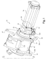
- reference numeral 22 suitable for use, for example, in single and/or multiple jam-resistant electromechanical actuating systems, such as single unit actuator system 20, shown in Figure 18.
- GRA 22 which is utilized, for example, for primary or secondary flight surface control, includes, as best seen in Figures 1 and 18, an input power source, such as a bidirectionally rotatable prime mover or mechanical power source, such as electric motor 24, the proximate end of which is fixedly secured, via a plurality of bolts 28, to a connector housing 26, which in turn is connected, via a plurality of further bolts 32, to grounded housing structures 30a, 30b, that include axially-spaced, separate, front and rear end flange portions 36 and 38, respectively, all of which will be described in more detail hereinafter.
- an edge surface of flange portion 38 is provided with an affixed load sensor 34, preferably in the form of a strain gauge of any desirable commercially available type.
- a rotatable or pivotable output structure 40 which functions to provide a mechanical connection to the load, i.e., the surface that needs to be controlled, with output member or structure 40 including an output flange portion 42, all of which will again be described in more detail hereinafter.
- the front end of GRA 22, extending axially beyond front end flange portion 36, is closed via a front hinge cover 46 that is secured to flange portion 36 via a plurality of bolts 48.
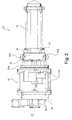
- a commercially available reversible or bidirectional rotary electric motor 24 which for the sake of electrical redundancy is shown here, for example, as a tandem dual motor assembly, includes dual circumferentially-spaced receptacles 50a, 50b ( Figure 2), located on the periphery of connector housing 26, that function for electrical connections to the dual motor windings, respectively, while a further receptacle 52, intermediate receptacles 50a, 50b, functions for electrical connections for the dual motor resolvers and commutators for logic/ motor position control and/or sensing in a manner well known in the art.
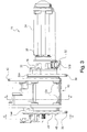
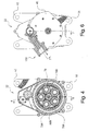
- FIGS 4 and 5 are transverse and longitudinal sectional views, respectively of GRA 22, rotational power from motor 24 is coupled (not shown per se) to an intermediate shaft 56, which has a sun gear 60, fixedly attached to the distal end thereof, with sun gear 60 functioning as an input member.
- Sun gear 60 is in meshed relationship with at least one planet gear 62 which also meshes with and reacts against a fixed internal ring gear 66 that is affixed to an end face of grounded housing structure 30a.
- a rotatable planet carrier 64 thus acts as the output member.
- This combination of intermeshing gears 60, 62, 66 and planet carrier 64 together comprise a supplementary or optional gearing speed reducer structure 70 that may or may not be required, depending upon the type and severity of service or moving force required of GRA 22.
- a central hub portion 72 of output planet carrier 64 is splined to the proximate end of a central, longitudinally-extending, preferably hollow input shaft 74, journalled in carrier 64 on its proximate end, may or may not extend completely through GRA 22 and is journalled, in this embodiment, on its distal end, in front hinge cover 46.
- Input shaft 74 at its about longitudinal center portion, includes a preferably integral hinge sun gear 76, forming a part of a hinge assembly planetary gear train 44, which meshes with the center portions or segments of a plurality of preferably hollow hinge planet gears 78 that include integral, axially-spaced, planet outer portions 78a, 78b, and planet center portions 78c.
- Planet outer portions 78a, 78b are longitudinally as well as radially spaced and separated about hinge sun gear 76 via longitudinally separated ring spacers 80.
- Grounded housing structures 30a, 30b in addition to their separate flange portions 36, 38, also include respective cylindrical portions 84a, 84b, each having stepped peripheral surfaces 86 as well as respective fixed, peripheral outer ring gear portions 88a, 88b that are also in respective meshing relationship with hinge planet gear portions 78a, 78b.
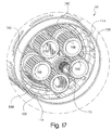
- hinge planet gear portions 78a, 78b revolve around hinge sun gear 76, with peripheral outer ring gear portions 88a, 88b, serving as reaction members. Portions of this gear train are also illustrated in Figure 8 and particularly in Figure 17.
- the center portions 78c of planet hinge gear 78 in addition to meshing with sun gear 76, also mesh with a rotatable, central internal ring gear 92, axially interposed between, but spaced from fixed ring gear portions 88a, 88b. It is the differential ratio between the outer internal ring gears 88a, 88b, / outer planet gear portions 78a, 78b, and the center ring gear portion 92/ center hinge planet gear portions 78c, that produce the motion of central internal ring gear 92 relative to the outer internal ring gear portions 88a, 88b. It should be understood that the previously-described hinge motion, achieved via planetary gear train 44, could also be achieved via other forms of power transmissions well known in the art.
- a cylindrically-extending portion 94 of output flange portion 42 of pivotable output structure 40 is rotatably journalled, via axially-spaced rolling element bearings 96 retained on spaced stepped peripheral surfaces 86 of housing structures 30a, 30b.
- cylindrical portion 94 connected to the load, together with output flange portion 42, can rotate or pivot relative to grounded housing structures 30a, 30b.
- the former is linked relative to the latter via an internal lock ring 100.
- output cylindrical portion 94 is also provided with opposed laterally extending tooth members 114 which are designed to correspond with tooth members 106 and 108...
- power is transferred from internal ring gear 92, through opposed teeth 108, to the mating teeth 106 on the radially innermost portions of lock plates 104a, 104b, then through the radially outermost portions of lock plate teeth 106, and finally into tooth members 114 on output member 94.
- Lock plates 104a, 104b are further provided with pluralities of circumferentially-spaced, laterally outwardly-directed dowel pins 116, each of which extends fully through laterally elongated apertures 118 ( Figures 10, 11) in output cylindrical portion 94 as well as at least extending into an individual skewed slot 122 ( Figures 9, 14) in a peripheral, cylindrical, lock collar 120 extending around, and rotatably moveable, relative to, the outer peripheral surface of output portion 94.
- a peripheral portion of lock collar 120 is provided with a sector gear 124 ( Figures 8, 9, and 13) of limited circumferential extent, preferably in the range of 15 to 45 degrees.
- sector gear 124 is adapted to be engaged with and reversibly driven by a spur gear train assembly 126 ( Figures 5, 8), thereby rotating lock collar 120 relative to output portion 94.
- Lock collar 120 is enclosed within a further multi-shape peripheral outer housing 130 whose inner axial end portion abuts output flange portion 42 and its outer axial end portion abuts at an intermediate cover 132, interposed between outer housing 130 and front hinge cover 46.
- outer housing 130 is secured, on one axial end, to output flange portion 42 and, on its other axial end, to intermediate cover 132 via a plurality of bolts 134. It should be understood at this time.
- pivotable output structure 40 including outer housing 130, intermediate cover 132 and flange portion 42, can move peripherally relative to grounded housing structures 30a, 30b, including their respective flange portions 38, 36.
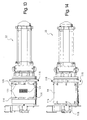
- This is graphically illustrated in Figure 2 wherein the sections G1 and G2 that remain stationary to ground are shown confined within broken lines, while the section R that rotates with the load, around rotational axis 136, is shown confined within the dotted lines.
- spur gear train assembly 126 located within a cavity defined by outer housing 130 and intermediate cover 132, is spur gear train assembly 126, of a decoupling mechanism 128, which can be reversibly rotated by an external driving source or actuator, such as electric connect/disconnect motor 138.
- an external driving source or actuator such as electric connect/disconnect motor 138.
- the exact structural details of the gear reduction sequence of gear train assembly 126 are not critical and are readily deducible by one of ordinary skill in the art. What is important is that a cluster gear 140 meshes with and drives sector gear 124 of cylindrical lock collar 120, and that a torque limiting clutch 142, of any desired conventional construction, functions to prevent possible overload damage to gear train assembly 126. It should, of course, be clear to those skilled in the art, that other embodiments of jam tolerance mechanisms may not require or need the use of a torque limiting clutch, such as 142.
- intermediate cover 132 includes a curved sector housing portion 144 that extends sectorially (not shown per se) for a predetermined angular range (of about 45 to 120 degrees, for example) around but not in contact with, a portion of grounded housing structure portion 30b and contains therein a curved sector gear 146 of about the same angular extent.
- Sector gear 146 operatively interacts with a gear portion of a commercially available rotary variable differential transformer (RVDT) 150 that is located within a housing portion 152 of front hinge cover 46 and closed via its own cover 154.
- RVDT rotary variable differential transformer
- RVDT 150 It is the function of RVDT 150 to serve as a position sensor, specifically of rotational angles, in a manner well known in the art, for determining the angular location or position of pivotable output structure 40, relative to grounded housing structure 30b, for control purposes to be described in detail, later.
- RVDTs utilize rotary ferromagnetic cores and are capable of continuous rotational measurement. Again, the exact structural details of RVDT 150 are not critical and are easily deducible by one of ordinary skill in the art. What is important is the determination of the angular location of the pivotable output structure relative to the grounded housing structure, which in addition to using an RVDT, could also be accomplished by other position sensors such as, e.g., potentiometers, resolvers and syncros.
- such a position sensor could also be incorporated into the overall system, without being physically attached to the actuator, i.e., it could be mounted directly between the vehicle structure and the surface or item it senses as a separate physical unit that is electrically connected to the system.
- FIG. 1 Figures 1, 5 and 15, 16 illustrate same in the normal operation thereof, i.e., when pivotable output structure 40 is mechanically coupled to grounded housing structure 30a, 30b, via the previously-noted intermeshing of tooth portions 106-108 and 114.
- the load i.e., the previously-noted movable surface that is controlled therewith.
- this invention contemplates that each such movable surface, for the sake of redundancy, is controlled via independent multiples of GRAs 22.
- bidirectional main motor 24 operates, via control line 174, to pivot the noted movable surfaces or load 40, as directed, and as illustrated in Figure 18, by a vehicle computer 160, acting via Command 180 and Power 182 inputs, through an electronic controller 162, which in turn controls the function of main motor 24 and, as will be discussed later, also controls the function of disconnect motor 138 via line 176.
- a Status input 184 relays required information from controller 162 back to vehicle computer 160, with controller 162 receiving at least some of the following inputs from GRA 22:
- decoupling mechanism 128 Upon the detection of a malfunction, such as, for example of a jam or other failure, of GRA 22, as determined by electronic controller 162, based on one or more of the just noted GRA inputs, decoupling mechanism 128 serves to completely sever the load path between GRA 22 and the load.
- decoupling mechanism 128 includes the previously-recited spur gear train assembly 126, driven by reversible/bidirectional disconnect motor 138, whose cluster gear 140 meshes with and drives sector gear 124 of cylindrical lock collar 120.
- Rotational movement of lock collar 120 causes multiple dowel pins 116, extending radially outwardly from opposed lock plates 104a, 104b, and extending through laterally-elongated apertures 118, in cylindrical portion 94, as well as extending into the individual, skewed, peripheral slots 122 (in lock collar 120), to be axially displaced and thereby driving lock plates 104a, 104b, out of engagement with the opposed mating portions of cylindrical portion 94 and the mating side portions of central internal ring gear 92, resulting in the complete disengagement of the intermeshing of tooth portions 106-108 and 114.
- the above decoupling method or process can, of course, also be reversed, at any time, (by driving disconnect motor 138 in a reverse or connect direction) to thereby re-couple the load to GRA 22.
- GRA 22 is provided with sensing device or strain gage 34 to sense or measure, either directly or indirectly, the load present or occurring at output member or structure 42.
- the system control can then compare the input load (either by direct or indirect measurement, such as via main motor current, and the like) to the output load, as well as the input speed and the output speed (using position and/or velocity sensors at main motor 24 and the load). This comparison, either by itself or used in conjunction with readings from additional redundant GRA(s) can be used to detect if a jam or other type of failure has occurred within GRA 22 or its control.
- the above-recited two features allow system 20 to detect a jam or other failure and isolate same from the remainder of the system 20 by activating the decoupling mechanism in the failed GRA unit 22.
- a failed GRA 22 can be effectively removed from system 20 without detriment to the remaining operative or healthy GRAs.
- a single computer 160 together with a single controller 162 can be utilized to control and monitor multiple GRAs 22. This removal of a failed GRA 22 will permit continued overall system function with full rate capability and load capability, reduced by one GRA over the total number of GRAs being utilized.
- the system is designed to produce a certain amount of load at a certain speed.
- the load that the system produces is the sum of the loads from each GRA.
- the electronic controller 162 in conjunction with the vehicle computer 160, may instruct GRA 20 to transition the load to a fixed neutral location. It should be understood that when using these GRAs, a system can never employ but a single actuator since the ability to tolerate a jam depends on having another GRA, other than the jammed one, to carry on the required operations. It should also be clear that it is the decision of those in charge of the vehicle computers as to whether to continue operation when only a single operative actuator remains or whether to revert to a safe mode and hold the item being controlled at a fixed, safe position.
- system 20 has an additional feature in that it is also able to monitor trends in the relationship between GRA input power and output power as a part of a prognostic health or operational monitoring regime. This additional feature thus imparts the ability to detect certain impending failures before they actually occur and provide an alert signal to service the about-to-be impaired GRA prior to complete failure.
- the development of equipment health monitoring algorithms is still underway and testing thereof will be required before there can be quantitative characterization of actuator degradation, but upon the completion of this development, the systems of this invention are deemed to be capable of providing all of the information necessary for these systems to detect imminent faults.
- the approach, in the method or process of the present invention, namely of severing the mechanical link of a power transmission device, at the load, while utilizing a completely reversible method or process is unique. This allows the decoupling mechanism 128 to potentially be tested prior to each use to eliminate the possibility of latent failures.
- the ability of the method or process of the system of this invention to actively control the decoupling also allows for GRA unit 22 to be decoupled for reasons other than mechanical overload. If a failure in system 20, that causes GRA unit 22 to decouple is determined to originate outside of unit 22, unit 22 can be re-coupled an reused without the need for removal, refurbishment, or maintenance.
- the method/process of the present invention may best be described in the system's employment of the features or characteristics as follows: First, reversible disengagement, without human intervention, (testable on the vehicle) and the disengagement of GRA 22 from the load at or as close as is practicable to the output (closest to load). Second, actuator fault (any type of failure or degradation) is determined by monitoring, at a minimum, main motor speed, main motor load, and output load. It should be understood that "motor” is deemed to refer to any source of mechanical power, i.e., electric motor, hydraulic motor, hand crank, etc., with this monitoring then activating the electronically controlled disengagement of the power transmission device, at the load. Furthermore, the method/process of system 20 is intended to cover all embodiments involving electronically controlled reversible disengaging load paths for mechanical power actuation.
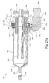
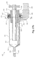
- Linear actuator 222 is electromechanically driven by a conventional ball screw 224, best shown in Figures 27a, 27b, and a unique, special ball nut 226.
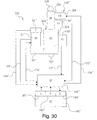
- Linear actuator 222 is suitable for use, for example, in single and/or multiple jam-resistant electromechanical actuating systems, such as the actuator system 220 shown in Figure 30.
- jam tolerance cannot be achieved with only one actuator and the more actuators there are in a system, the more jams can be tolerated, e.g., if there are four actuators in the system, up to three jams can be tolerated as there will still be one actuator left to continue operation.
- Linear actuator 222 is again utilized among other things, for example, for primary and secondary flight surface control, similar to that of GRA 22 of the first embodiment of this invention and includes, as best shown in Figures 21a, 21b, 22 and 25a, 25b, unique, special ball nut 226, to be described in detail hereinafter, that is normally driven by rotatable ball screw 224, driven in turn by a schematically illustrated ( Figure 30), bidirectionally rotatable prime mover or main motor 24", such as a conventional electric motor which may, if necessary, further include a conventional speed reducer gearbox 70" (again, schematically shown in Figure 30), with all of the schematically-illustrated items being well known in the art and readily commercially available.
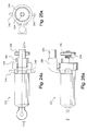
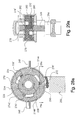
- Figures 24a-29a show the arrangement of the components of linear actuator 222 in the coupled position
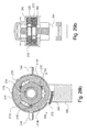
- Figures 24b-29b show same in the uncoupled position. The components themselves are the same in the noted two sets of Figures.
- ball screw 224 having an input gear 230, extends through an axial central aperture 228 of generally-cylindrical ball nut 226 and is in operative engagement therewith, so that rotation of the ball screw results in axial displacement of the ball nut in the conventional manner.
- ball nut 226 is axially retained in an openended, diametrically enlarged, stepped, rear cylindrical portion 234 of a generally cylindrical output rod 232 and secured against axial movement, relative to output rod 232, via a ring-shaped closure member 244 affixed to output rod rear portion 234.
- Output rod 232 further includes a front portion 236 that terminates into a clevis-type output member 238 having a central aperture 240 adapted for a further, e.g., pin-type connection.
- Ball nut 226 is prevented from rotational movement via two opposite, radially outwardly-directed trunnions 246, 248 ( Figure 24), fixedly extending from ball nut 226, through corresponding apertures in output rod 232, at an axial portion thereof proximate to closure member 244.
- Ball screw 224 with input gear 230, extending through the center of ball nut 226.
- Ball nut 226, on its outer peripheral surface 252 is provided with preferably three peripherally equally angularly spaced, axially-extending, raised portions of generally tooth-like members 254, 256 and 258, each having a front portion "a” axially spaced from a rear portion "b” as well as axially-spaced, dual-angled, generally rectangular, allochiral (or mirror image) end portions 260, 262, which in turn are axially separated by laterally abutting, trapezoidal spaces 264, 266 that share a common, short parallel center axial side.
- annular front locking plate 270 located around ball nut 226, at spaces 264, 266, is an annular front locking plate 270 having a smooth peripheral outer surface except for the addition of a radially-extending sector face gear portion 272, as well as three equally-spaced, radially inwardly-extending curved sector portions 274a, 274b, 274c, (Figure 28) each of which merges, at one end, into an axially-extending tooth portion 278 ( Figure 29a) having a generally trapezoidal shape adapted to engage, in an operative position, with trapezoidal spaces 266 between tooth-like members 254a,b; 256a,b; and 258a,b, respectively.
- FIG 23, and particularly Figure 22, also show a rear locking plate 270' which is essentially the same as front locking plate 270, only installed in the reversed position (or turned around), with like parts thus being identified with prime (') symbols.
- Rear locking plate 270' which is circumferentially slightly offset, relative to front locking plate 270, as best seen in Figures 20, and 23, has its tooth portions 278' ( Figures 28a, 28b) adapted to engage with trapezoidal spaces 268 between tooth-like members 254a,b; 256a,b and 258a,b, respectively.
- Locking plates 270, 270' are axially separated from each other, as well as from output rod 232 and closure member 244, respectively, via three, spaced and interposed radial thrust, rolling element bearings, such as roller bearings 282, as best seen in Figures 23 and 27.
- a depending flat portion 280 ( Figure 27) of output rod 232 serves as a mating and attachment surface for the speed reducer gear box 286 of a mode or indexing bidirectional or reversible actuator, such as electric motor 284, the output member of gear box 286 taking the form of a dual radial face mesh gear 290 having oppositely directed gear face portions 292, 292' that operatively respectively mesh with sector face gear portions 272, 272' of locking plates 270, 270'.
- Figs 27a-29a illustrate same during normal operation thereof, i.e., when output rod 232 is mechanically coupled to the grounded housing structure (not shown per se), via the previously-noted intermeshing or coupling of ball nut 226 with the tooth portions 278, 278' of locking plates 270, 270', respectively.
- main motor 24 in the coupled or engaged stage/state, main motor 24", affixed to a non-illustrated grounded housing portion and acting through a conventional gear box or speed reducer 70", transfers the rotary motion or torque, via rotatable ball screw 224, to axially-retained ball nut 226, thus converting the ball screw's rotary motion to linear, axially reciprocatory movement of the ball nut, depending upon the angular direction of rotation of ball screw 224.
- ball nut 226 can be coupled and uncoupled to output rod 232 via disconnect motor 284, gear box 286, face gears 292, 292' and sector gears 272, 272' of locking plates 270, 270', respectively.
- Output rod 232 in turn, is mechanically interconnected (not shown) to the load, i.e., the movable surface that is controlled therewith.
- bidirectional main motor 24 via line 174
- a Status 184" input relays required information from controller 162" back to vehicle computer 160", with controller 162" receiving at least some of the following inputs from linear actuator 222:
- decoupling mechanism 128 Upon the detection of a malfunction, such as, for example of a jam or other failure, of linear actuator 222, as determined by electronic controller 162", based on one or more of the just recited linear actuator inputs, decoupling mechanism 128" serves to completely sever the load path between linear actuator 222 and the load.
- decoupling mechanism 128" includes previously-recited face gear 290, driven by reversible/bidirectional disconnect motor 284 via reducer gearbox 286, and locking plates 270, 270'.
- linear actuator 222 is provided with sensing device or strain gage 34" to sense or measure, either directly or indirectly, the load present or occurring at output member or rod structure 232.
- the system control can then compare the input load (either by direct or indirect measurement, such as via main motor current, and the like) to the output load, as well as the input speed and the output speed (using position and/or velocity sensors at main motor 24" and the load). This comparison, either by itself or used in conjunction with readings from additional linear actuators can be used to determine if a jam or other type of failure has occurred within linear actuator 222 or its control.
Landscapes
- Engineering & Computer Science (AREA)
- Automation & Control Theory (AREA)
- Aviation & Aerospace Engineering (AREA)
- Power Engineering (AREA)
- Transmission Devices (AREA)
- Retarders (AREA)
Abstract
Description
Claims (16)
- In a vehicle, having a fixed supporting structure (30a, 30b) and a load movable relative thereto, a jam tolerant actuating system (20, 220) including a computer (160, 160"), control means (162, 162") and at least two electromechanical actuator assemblies (22, 222), each of said actuator assemblies (22, 222) further including a main motor (24, 24") for providing motion force therefore; a load sensor (34, 34") and a position sensor (150, 150") on said actuator assembly (22, 222); a coupling/decoupling mechanism (128, 128"), positioned at an output member (40, 238) of said actuator assembly (22, 222), for severing the load path between said actuator assembly (22, 222) and said load; and a disconnect actuator (138, 284) for providing motive force for said coupling/decoupling mechanism (128, 128"), characterized in that a method for controlling said actuating system, (20, 220) comprises the steps of:a. actuating said load by said actuator assembly (22, 222) via said main motor (24, 24"), as directed by said computer (160, 160") via Command (180, 180") and Power (182, 182") inputs through said control means (162, 162");b. relaying, from said control means (162, 162") to said computer (160, 160") a plurality of the following inputs;i. main motor speed (166, 166") from a main motor commutator (52, 52");ii. main motor current (168, 168");iii. actuator assembly output load (170, 170") from said load sensor (34, 34"); andiv. actuator assembly output position (172, 172"), processed to determine speed, from said position sensor (150, 150"); andc. completely severing, via decoupling, the load path between said actuator assembly (22, 222) and said load, via driving said coupling/decoupling mechanism (128, 128") in one direction, upon the detection of a malfunction, as determined by said control means (162, 162"), based on at least three of the above i., ii., iii., and iv. inputs.
- The method for controlling of claim 1, further including the step of:d. reversing the previous decoupling step, at any time, thereby reestablishing the load path, between said actuator assembly (22, 222) and said load, by driving said coupling/decoupling mechanism (128, 128") in a reverse direction.
- The method for controlling of claim 2, further including the steps of:e. indirectly measuring, via said load sensor (34, 34"), the load present or occurring at the output member (40, 238) of said actuator assembly (22, 222);f. indirectly measuring, the actuator assembly input load (168, 168"); andg. comparing said input (168, 168") and output (170, 170") loads to detect if a jam or other type of failure has occurred within said actuator assembly (22, 222) or said control means (162, 162").
- The method for controlling of claim 3, wherein said comparing of input (168, 168") and output (170, 170") loads is limited to one of said actuator assemblies (22, 222) and wherein said comparing of input (168, 168") and output (170, 170") loads is used in conjunction with similar readings from additional, redundant, actuator assemblies (22, 222).
- The method for controlling of claim 1, characterized in that said actuator assemblies (22, 222) include rotary actuators (22).
- The method for controlling of claim 5, characterized in that said rotary actuators (22) are comprised of geared rotary actuators (22).
- The geared rotary actuators (22) of claim 6, with each of said actuators (22) including a compound planetary gear set (44), wherein a central internal ring gear (92), having laterally-spaced first edge engagement members (108), is operatively interconnected, in one operating position, to an output member (40) attached to said load, via laterally-spaced and laterally movable opposed lock plates (104a, 104b), said lock plates (104a, 104b) having laterally-spaced second edge engagement members (106) and radially-extending pins (116), said second edge engagement members (106), in one operative position, being adapted to operatively interact with their respective first edge engagement members (108); an engagement/disengagement collar (120) having a plurality of peripheral cam slots (118), with said pins (116) entering said cam slots (118); a sector gear (124) located on a peripheral portion of said collar (120), said sector gear (124) being in operative engagement with said disconnect actuator (138), the latter (138), depending upon the direction of rotation, coupling/uncoupling said output member (40) with said rotary geared actuator (22) via rotation of said collar (120), which in turn results, via movement of said pins (116), in the lateral movement of said lock plates (104a, 104b) and in one of the engagement and disengagement of said first (108) and second (106) engagement members.
- The method for controlling of claim 1, characterized in that said actuator assemblies 22, 222) include linear actuators (222).
- The method for controlling of claim 8, characterized in that said linear actuators (222) are comprised of ball screw actuators (222).
- The ball screw actuators of claim 9, with each of said actuators (222) including a bidirectionally rotatable power driven ball screw (224); a reciprocable ball nut (226) having peripherally-spaced outward first surface engagement portions (264, 266), driven by said ball screw (224), said ball nut (226) being operatively interconnected in one operating position, to an output member (238) attached to said load, via laterally adjacent and oppositely rotationally movable front and rear locking plates (270, 270'), said locking plates (270, 270') having respective peripherally-spaced inward second surface engagement portions (278, 278') and respective radially extending sector gear portions (272, 272'), said second surface engagement portions (278, 278'), in one operative position, being adapted to operatively interact with said first surface engagement portions (264, 266); said sector gear portions (272, 272') being in operative engagement with opposite sides of a face gear (290) of said disconnect actuator (284), the latter (284), depending upon the direction of rotation, coupling/uncoupling said output member (238) with said ball screw actuator (222) via rotation of said sector gear portions (272, 272'), which in turn results, via movement of said sector gear portions (272, 272'), in the peripheral movement of said locking plates (270, 270') and in one of the engagement and disengagement of said first (264, 266) and second (278, 278') engagement portions.
- In a vehicle having a fixed supporting structure (30a, 30b) and a load movable relative thereto, a jam tolerant actuating system (20, 220) including the following operatively interconnected components: a computer (160, 160"); an electronic decision-making controller (162, 162"); and at least two rotary geared actuator assemblies (22, 222), each of said actuator assemblies (22, 222) further including a main mechanical power source (24, 24") for providing motion force therefore; a load sensor (34, 34") and a position sensor (150, 150") on said actuator assembly (22, 222); a coupling/uncoupling mechanism (128, 128"), positioned at the output member (40, 238) of each actuator assembly (22, 222), for completing/severing the load path between said actuator assembly (22, 222) and said load; and a disconnect mechanical power source (138, 284) for providing motive force for said coupling/decoupling mechanism (128, 128"), each of said actuator assemblies (22, 222) being characterized in that it includes a rotary geared actuator (22) comprised of::a. a compound planetary gear set (44), wherein a central ring gear (92), having opposing, laterally-spaced, first edge engagement members (108), is operatively interconnected, in one operating position, to said output member (40) attached to said movable load; viab. laterally-spaced and laterally movable opposed lock plates (104a, 104b), said lock plates (104a, 104b) having laterally-spaced second edge engagement members (106) and radially extending pins (116), said second edge engagement members (106), in one operative position, being adapted to operatively interact with respective adjacent ones of said first engagement members (108);c. an engagement/disengagement collar (120) having a plurality of peripherally extending cam slots (118), with said pins (116) entering said cam slots (118); andd. a sector gear (124) located on a peripheral portion of said collar (120), said sector gear (120) being in operative engagement with said disconnect mechanical power source (138), the latter (138), depending upon the direction of movement, coupling/uncoupling said output member (40) with said rotary geared actuator assembly (22) via rotation of said collar (120), which in turn results, via movement of said pins (116), in the lateral movement of said lock plates (104a, 104b) and in one of the engagement and disengagement of said first (108) and second (106) engagement members.
- In the jam tolerant actuating system (20, 220) of claim 11, a process of controlling said system (20, 220) including the following steps:a. actuating said load via said actuator assembly (22) as directed by said decision making controller (162) via Command (180) and Power (182) inputs from and Status (184) input to said computer (160);b. relaying, from said controller (162) to said computer (160), at least three of the following inputs:i. speed (166) of the main mechanical power source (24);ii. main mechanical power source load (168);iii. actuator assembly output load (170) from said load sensor (34); andiv. actuator assembly output position (172), processed to determine speed, from said position sensor (150); andc. decoupling, via completely severing, the load path between said actuator assembly (22) and said load, via driving said coupling/uncoupling mechanism (128) in one direction, upon detection of a malfunction, as determined by said controller (162), based on said inputs of step b.
- The process of controlling of claim 12, further including the step ofd. reversing, at any time, the previous decoupling of step c., thereby reestablishing the load path, between said actuator assembly (22) and said load, by driving said coupling/uncoupling mechanism (128) in a direction opposite to said one direction.
- The jam tolerant actuating system (20, 220) of claim 11, characterized in that each of said actuating assemblies (22, 222) alternatively includes a linear actuator assembly (222) comprised of:a. a bidirectionally rotatable power driven ball screw (224);b. a reciprocable ball nut (226), actuated via said ball screw (224), having peripherally-spaced outward first surface engagement portions (264, 266), said ball nut (226) being operatively interconnected in one operative position, to said output member (238) attached to said movable load, viac. laterally adjacent and oppositely rotationally movable front (270) and rear (270') locking plates, said locking plates (270, 270') having respective peripherally-spaced inward second surface engagement portions (278, 278') and respective radially extending sector gear portions (272, 272'), said second surface engagement portions (278, 278'), in one operative position, being adapted to operatively interact with said first surface engagement portions (264, 266), said sector gear portions (272, 272') being in operative engagement withd. opposite sides of a face gear (290) of said disconnect mechanical power source (284), the latter (284), depending upon the direction of movement, coupling/uncoupling said output member (238) with said linear actuating assembly (222) via opposite rotation of said sector gear portions (272, 272'), which in turn, results, via movement of said sector gear portions (272, 272'), in the peripheral movement of said locking plates (270, 270') and in one of the engagement and disengagement of said first (264, 266) and second (278, 278') engagement portions.
- In the jam tolerant actuating system (20, 220) of claim 14, a process of controlling said system (20, 220) including the following steps:a. actuating said load via said linear actuator assembly (222) as directed by said decision making controller (162") via Command (180") and Power (182") inputs from and Status (184") input to said computer (160")b. relaying, from said controller (162") to said computer (160") at least three of the following inputs:i. speed (166") of the main mechanical power source (24");ii. main mechanical power source load (168");iii. actuator assembly output load (170") from said load sensor (34"); andiv. actuator assembly output position (172") processed to determine speed, from said position sensor (150"); andc. decoupling, via completely severing, the load path between said actuator assembly (222) and said load, via driving said coupling/uncoupling mechanism (128") in one direction, upon the detection of a malfunction, as determined by said controller (162") based on said inputs from step b.
- The process of controlling of claim 15, further including the steps of:d. measuring, via said load sensor (34"), the load present at said output member (238);e. measuring said actuator assembly input load (168"); andf. comparing said input (168") and output (170") loads to detect if a jam has occurred.
Applications Claiming Priority (2)
| Application Number | Priority Date | Filing Date | Title |
|---|---|---|---|
| US51150603P | 2003-10-15 | 2003-10-15 | |
| US511506P | 2003-10-15 |
Publications (2)
| Publication Number | Publication Date |
|---|---|
| EP1524188A2 true EP1524188A2 (en) | 2005-04-20 |
| EP1524188A3 EP1524188A3 (en) | 2014-09-03 |
Family
ID=34375596
Family Applications (1)
| Application Number | Title | Priority Date | Filing Date |
|---|---|---|---|
| EP20040256336 Withdrawn EP1524188A3 (en) | 2003-10-15 | 2004-10-14 | Jam tolerant electromechanical actuation systems and methods of operation |
Country Status (2)
| Country | Link |
|---|---|
| US (2) | US7100870B2 (en) |
| EP (1) | EP1524188A3 (en) |
Cited By (13)
| Publication number | Priority date | Publication date | Assignee | Title |
|---|---|---|---|---|
| EP1793477A1 (en) * | 2005-12-02 | 2007-06-06 | The Boeing Company | Fault-tolerant electro-mechanical actuator having a torque sensing control system |
| EP1785346A3 (en) * | 2005-11-15 | 2008-03-26 | Honeywell International Inc. | Flight control surface actuator assembly |
| WO2010046111A3 (en) * | 2008-10-22 | 2010-07-29 | Airbus Operations Gmbh | Adjuster device for an aircraft combination of an adjuster device and an adjuster device fault recognition function, fault -tolerant adjuster system and method for reconfiguring the adjuster system |
| DE102010044678A1 (en) | 2010-09-08 | 2012-03-08 | Airbus Operations Gmbh | Monitoring system for a control system of an aircraft, control system and method for reconfiguration of the control system |
| CN103241368A (en) * | 2012-02-10 | 2013-08-14 | Eads飞机设计有限公司 | Linear actuator and aircraft component comprising same |
| US8868261B2 (en) | 2010-09-08 | 2014-10-21 | Airbus Operations Gmbh | Monitoring device for an actuation system of an aircraft, actuation system and method for reconfiguring the actuation system |
| CN106394872A (en) * | 2012-08-22 | 2017-02-15 | 穆格伍尔弗汉普顿有限公司 | Control surface actuation assembly |
| EP4190686A1 (en) * | 2021-12-02 | 2023-06-07 | BAE SYSTEMS plc | Drive arrangements |
| EP4190692A1 (en) * | 2021-12-02 | 2023-06-07 | BAE SYSTEMS plc | Drive arrangements |
| EP4190693A1 (en) * | 2021-12-02 | 2023-06-07 | BAE SYSTEMS plc | Drive arrangements |
| WO2023099868A1 (en) * | 2021-12-02 | 2023-06-08 | Bae Systems Plc | Drive arrangements |
| WO2023099867A1 (en) * | 2021-12-02 | 2023-06-08 | Bae Systems Plc | Drive arrangements |
| US12397903B2 (en) | 2021-12-02 | 2025-08-26 | Bae Systems Plc | Strain wave gearing and drive arrangements |
Families Citing this family (42)
| Publication number | Priority date | Publication date | Assignee | Title |
|---|---|---|---|---|
| US7100870B2 (en) * | 2003-10-15 | 2006-09-05 | Parker-Hannifin Corporation | Jam tolerant electromechanical actuation systems and methods of operation |
| US7353608B2 (en) * | 2006-01-25 | 2008-04-08 | Custom Sensors & Technologies, Inc. | Multiple channel RVDT with dual load path and fail-safe mechanism |
| GB0616730D0 (en) * | 2006-08-23 | 2006-10-04 | Airbus Uk Ltd | Jam-tolerant actuator |
| US8230750B2 (en) * | 2006-09-01 | 2012-07-31 | Parker-Hannifin Corporation | Electromechanical actuating assembly |
| US8136418B2 (en) * | 2007-02-07 | 2012-03-20 | Parker-Hannifin Corporation | Electromechanical actuating assembly |
| WO2008123813A1 (en) * | 2007-03-18 | 2008-10-16 | Stridsberg Innovation Ab | Releasable coupling for jamming handling |
| US20090076687A1 (en) * | 2007-09-19 | 2009-03-19 | Brose Schliesssysteme Gmbh & Co. Kg | Position detection arrangement for a moveable functional element which can be positioned motor-driven in a motor vehicle |
| US8336817B2 (en) | 2007-10-30 | 2012-12-25 | Parker-Hannifin Corporation | Jam tolerant electromechanical actuation systems and methods of operation |
| US8336818B2 (en) * | 2007-10-30 | 2012-12-25 | Parker-Hannifin Corporation | Jam tolerant electromechanical actuation systems and methods of operation |
| FR2924538B1 (en) * | 2007-11-30 | 2010-01-22 | Sagem Defense Securite | METHOD FOR MONITORING THE PERFORMANCE OF AN ELECTROMECHANICAL ACTUATOR OF THE ROTOLINE TYPE |
| DE102008022092A1 (en) * | 2008-05-05 | 2009-11-19 | Airbus Deutschland Gmbh | Fault-tolerant control system for adjusting the flaps of an aircraft with adjustable kinematics with a fixed axis of rotation |
| ES2493640T3 (en) * | 2008-06-13 | 2014-09-12 | Moog Inc. | Method for determining the apparent functional integrity of a non-return device |
| EP2401525B1 (en) * | 2009-02-25 | 2018-12-05 | Exlar Corporation | Actuation system and method of generating a rotary output |
| ITMO20090176A1 (en) * | 2009-07-07 | 2011-01-08 | Penta Automazioni Di Molinaro Raffa Ele | LUDIC DEVICE WITH A PERFECT COIN. |
| US8109165B2 (en) * | 2009-09-29 | 2012-02-07 | Hamilton Sundstrand Corporation | Compliant non-jamming end of travel stop for a ball screw actuator |
| WO2011057633A2 (en) * | 2009-11-11 | 2011-05-19 | Vestas Wind Systems A/S | Improved control of wind turbine blade lift regulating means |
| US8794084B2 (en) * | 2010-03-18 | 2014-08-05 | Parker-Hannifin Corporation | Jam-tolerant electromechanical actuator |
| JP5382543B2 (en) * | 2010-06-25 | 2014-01-08 | 新東工業株式会社 | Electric cylinder control method and electric cylinder control system |
| EP2415669B1 (en) | 2010-08-04 | 2015-05-13 | AIRBUS HELICOPTERS DEUTSCHLAND GmbH | Control system |
| US10065728B2 (en) | 2011-06-30 | 2018-09-04 | Parker-Hannifin Corporation | Horizontal stabilizer trim actuator failure detection system and method using position sensors |
| JP6000527B2 (en) | 2011-11-02 | 2016-09-28 | ナブテスコ株式会社 | Electric actuator, electric actuator power cutting method, and electric actuator power cutting device |
| FR2988797B1 (en) * | 2012-04-02 | 2015-04-24 | Sagem Defense Securite | ELECTROMECHANICAL FLOATING SURFACE ACTUATOR FOR AIRCRAFT AND AIRCRAFT PROVIDED WITH SUCH AN ACTUATOR |
| TWI518265B (en) * | 2013-04-19 | 2016-01-21 | Moteck Electric Corp | Electric putter release device |
| CN104179913B (en) * | 2013-05-21 | 2018-05-11 | 模帝科电子科技股份有限公司 | releasing device of electric push rod |
| FR3016607B1 (en) * | 2014-01-20 | 2016-01-22 | Sagem Defense Securite | ACTUATOR FOR CONTROLLING A HORIZONTAL STABILIZATION PLAN OF AN AIRCRAFT |
| EP2915744B1 (en) * | 2014-03-05 | 2018-01-31 | Goodrich Actuation Systems SAS | Flight control actuator drive |
| US10689097B2 (en) | 2014-05-16 | 2020-06-23 | Bombardier Inc. | Actuators and methods for aircraft flight control surfaces |
| JP6556457B2 (en) | 2015-02-03 | 2019-08-07 | ナブテスコ株式会社 | Electric actuator and gear mechanism |
| US9290272B1 (en) * | 2015-02-10 | 2016-03-22 | Ami Industries, Inc. | Decoupled aircraft seat actuator |
| US9725176B2 (en) | 2015-02-10 | 2017-08-08 | Ami Industries, Inc. | Dual-function seat actuator |
| WO2015156705A2 (en) | 2015-05-06 | 2015-10-15 | Zakrytoe Aktsionernoe Obschestvo "Diakont" | Transmission gear, roller reducer comprising the transmission gear, and method of assembly thereof |
| US10933978B2 (en) | 2017-01-10 | 2021-03-02 | Parker-Hannifin Corporation | Moving end electronic detection of secondary load path engagement of aircraft flight control actuator |
| US11060593B2 (en) | 2018-10-19 | 2021-07-13 | Hamilton Sundstrand Corporation | Jam-tolerant electric rotary actuator |
| CN110525639A (en) * | 2019-07-26 | 2019-12-03 | 上海航天控制技术研究所 | A kind of appearance obstruction differential type dual-redundancy steering engine |
| JP7283304B2 (en) * | 2019-08-23 | 2023-05-30 | ニデックパワートレインシステムズ株式会社 | electric actuator |
| WO2021115635A1 (en) * | 2019-12-13 | 2021-06-17 | Eaton Intelligent Power Limited | Monitoring actuator system health |
| US11608161B2 (en) | 2020-04-08 | 2023-03-21 | The Boeing Company | Flap actuation systems and related methods |
| JP7694227B2 (en) * | 2021-02-19 | 2025-06-18 | 日本精工株式会社 | Electric actuator, control device and control program |
| US11454305B1 (en) | 2021-06-11 | 2022-09-27 | Whippany Actuation Systems Llc | Jam free linear actuation system implementing a mechanical disengagement mechanism and process thereof |
| US11624429B1 (en) * | 2021-07-28 | 2023-04-11 | The United States Of America As Represented By The Secretary Of The Navy | Compact linear drive mechanism |
| US12428137B2 (en) | 2021-12-02 | 2025-09-30 | Bae Systems Plc | Drive arrangements |
| EP4275936A1 (en) * | 2022-05-13 | 2023-11-15 | Goodrich Actuation Systems Limited | Dual motor drive system for actuator |
Family Cites Families (23)
| Publication number | Priority date | Publication date | Assignee | Title |
|---|---|---|---|---|
| US710870A (en) * | 1902-05-16 | 1902-10-07 | Henry P King | Storage battery. |
| US3958779A (en) * | 1975-05-27 | 1976-05-25 | Fairchild Industries Inc. | Aircraft control system with a jam isolating coupling |
| US4608527A (en) * | 1982-12-20 | 1986-08-26 | Sundstrand Corporation | Phase advance waveform generator for brushless DC actuator system controller |
| US4575027A (en) * | 1983-05-16 | 1986-03-11 | Lockheed Corporation | Electromechanical actuator system with anti-jamming features |
| US4544052A (en) * | 1984-03-12 | 1985-10-01 | Allied Corporation | Resettable disconnect device for rotating machines |
| US4637272A (en) * | 1985-10-28 | 1987-01-20 | Sundstrand Corporation | Ballscrew actuator |
| US4885939A (en) * | 1988-01-21 | 1989-12-12 | Lumex, Inc. | Dynamometer for testing eccentric contractions and concentric contractions with free-limb acceleration |
| US4877120A (en) * | 1988-03-08 | 1989-10-31 | Sunstrand Corp. | Actuator mechanism having adjustable stop |
| US4932613A (en) * | 1988-06-24 | 1990-06-12 | Curtiss-Wright Flight Systems, Inc. | Rotary hinge actuator |
| US4979700A (en) * | 1988-10-28 | 1990-12-25 | Curtiss Wright Flight Systems, Inc. | Rotary actuator for leading edge flap of aircraft |
| US5120285A (en) * | 1990-10-01 | 1992-06-09 | Sundstrand Corporation | Jam tolerant geared rotary actuator for multiple actuator systems with a single prime mover |
| US5071397A (en) * | 1990-10-01 | 1991-12-10 | Sundstrand Corporation | Jam tolerant geared rotary actuator with automatic disconnect |
| US5144851A (en) * | 1991-08-01 | 1992-09-08 | Sundstrand Corp. | Jam tolerant linear actuator |
| US5518466A (en) * | 1994-11-29 | 1996-05-21 | Curtiss Wright Flight Systems Inc. | Jam-tolerant rotary actuator |
| US6231012B1 (en) * | 1996-05-15 | 2001-05-15 | Michael J. Cacciola | No-back/offset gear box |
| US5779587A (en) * | 1996-08-30 | 1998-07-14 | Curtiss Wright Flight Systems, Inc. | Jam tolerant rotary actuator with shear pins and disengagement coupling |
| US5947246A (en) * | 1998-07-16 | 1999-09-07 | Emerson Electric Company | Overload clutch and detector plate assembly |
| GB9911049D0 (en) * | 1999-05-12 | 1999-07-14 | Lucas Ind Plc | Rotary actuator and system |
| US6260799B1 (en) * | 2000-04-24 | 2001-07-17 | Hamilton Sunstrand Corporation | Aircraft wing fold actuation system |
| GB0117904D0 (en) * | 2001-07-23 | 2001-09-12 | Lucas Industries Ltd | Motor control system |
| GB0127254D0 (en) * | 2001-11-13 | 2002-01-02 | Lucas Industries Ltd | Aircraft flight surface control system |
| US6705570B1 (en) * | 2003-04-14 | 2004-03-16 | Curtiss-Wright Controls, Inc. | Arrangement and associated system having an actuator and a tubular flap-drive member about the actuator |
| US7100870B2 (en) * | 2003-10-15 | 2006-09-05 | Parker-Hannifin Corporation | Jam tolerant electromechanical actuation systems and methods of operation |
-
2004
- 2004-08-17 US US10/920,107 patent/US7100870B2/en not_active Expired - Lifetime
- 2004-10-14 EP EP20040256336 patent/EP1524188A3/en not_active Withdrawn
-
2006
- 2006-09-01 US US11/469,531 patent/US7410132B1/en not_active Expired - Lifetime
Cited By (22)
| Publication number | Priority date | Publication date | Assignee | Title |
|---|---|---|---|---|
| EP1785346A3 (en) * | 2005-11-15 | 2008-03-26 | Honeywell International Inc. | Flight control surface actuator assembly |
| US7610828B2 (en) | 2005-11-15 | 2009-11-03 | Honeywell International Inc. | Flight control surface actuator assembly including a free trial mechanism |
| EP1793477A1 (en) * | 2005-12-02 | 2007-06-06 | The Boeing Company | Fault-tolerant electro-mechanical actuator having a torque sensing control system |
| WO2010046111A3 (en) * | 2008-10-22 | 2010-07-29 | Airbus Operations Gmbh | Adjuster device for an aircraft combination of an adjuster device and an adjuster device fault recognition function, fault -tolerant adjuster system and method for reconfiguring the adjuster system |
| CN102196964A (en) * | 2008-10-22 | 2011-09-21 | 空中客车营运有限公司 | Adjuster device for an aircraft, combination of an adjuster device and an adjuster device fault recognition function, fault-tolerant adjuster system and method for reconfiguring the adjuster system |
| CN102196964B (en) * | 2008-10-22 | 2017-01-18 | 空中客车营运有限公司 | Adjuster device for an aircraft, combination of an adjuster device and an adjuster device fault recognition function, fault-tolerant adjuster system and method for reconfiguring the adjuster system |
| DE102010044678A1 (en) | 2010-09-08 | 2012-03-08 | Airbus Operations Gmbh | Monitoring system for a control system of an aircraft, control system and method for reconfiguration of the control system |
| WO2012031759A2 (en) | 2010-09-08 | 2012-03-15 | Airbus Operations Gmbh | Monitoring device for an actuation system of an aircraft, actuation system and method for reconfiguring the actuation system |
| US8868261B2 (en) | 2010-09-08 | 2014-10-21 | Airbus Operations Gmbh | Monitoring device for an actuation system of an aircraft, actuation system and method for reconfiguring the actuation system |
| CN103241368B (en) * | 2012-02-10 | 2017-04-26 | Eads飞机设计有限公司 | Linear actuator and aircraft component comprising same |
| CN103241368A (en) * | 2012-02-10 | 2013-08-14 | Eads飞机设计有限公司 | Linear actuator and aircraft component comprising same |
| CN106394872A (en) * | 2012-08-22 | 2017-02-15 | 穆格伍尔弗汉普顿有限公司 | Control surface actuation assembly |
| EP3144220A1 (en) * | 2012-08-22 | 2017-03-22 | Moog Wolverhampton Limited | Aircraft control surface actuator |
| CN106394872B (en) * | 2012-08-22 | 2018-11-09 | 穆格伍尔弗汉普顿有限公司 | Control surface drive component |
| EP4190686A1 (en) * | 2021-12-02 | 2023-06-07 | BAE SYSTEMS plc | Drive arrangements |
| EP4190692A1 (en) * | 2021-12-02 | 2023-06-07 | BAE SYSTEMS plc | Drive arrangements |
| EP4190693A1 (en) * | 2021-12-02 | 2023-06-07 | BAE SYSTEMS plc | Drive arrangements |
| WO2023099868A1 (en) * | 2021-12-02 | 2023-06-08 | Bae Systems Plc | Drive arrangements |
| WO2023099867A1 (en) * | 2021-12-02 | 2023-06-08 | Bae Systems Plc | Drive arrangements |
| US12397903B2 (en) | 2021-12-02 | 2025-08-26 | Bae Systems Plc | Strain wave gearing and drive arrangements |
| US12404009B2 (en) | 2021-12-02 | 2025-09-02 | Bae Systems Plc | Drive arrangements |
| US12409928B2 (en) | 2021-12-02 | 2025-09-09 | Bae Systems Plc | Drive arrangements |
Also Published As
| Publication number | Publication date |
|---|---|
| US20080203221A1 (en) | 2008-08-28 |
| US7410132B1 (en) | 2008-08-12 |
| US20050103928A1 (en) | 2005-05-19 |
| US7100870B2 (en) | 2006-09-05 |
| EP1524188A3 (en) | 2014-09-03 |
Similar Documents
| Publication | Publication Date | Title |
|---|---|---|
| US7410132B1 (en) | Jam tolerant electromechanical actuation systems and methods of operation | |
| US8336817B2 (en) | Jam tolerant electromechanical actuation systems and methods of operation | |
| US8336818B2 (en) | Jam tolerant electromechanical actuation systems and methods of operation | |
| US8267350B2 (en) | Jam-tollerant actuator | |
| EP3144220B1 (en) | Aircraft control surface actuator | |
| US12404009B2 (en) | Drive arrangements | |
| US12397903B2 (en) | Strain wave gearing and drive arrangements | |
| EP4440931B1 (en) | Drive arrangements | |
| EP3054194A1 (en) | Electric actuator and gear mechanism | |
| EP1310699A2 (en) | Rotary actuator | |
| JPH0833168B2 (en) | Non-faulty mechanical rotary actuator | |
| EP4440929B1 (en) | Drive arrangements | |
| EP4190691A1 (en) | Drive arrangements | |
| EP4191088A1 (en) | Strain wave gearing and drive arrangements | |
| EP4190686A1 (en) | Drive arrangements | |
| GB2613380A (en) | Strain wave gearing and drive arrangements | |
| GB2613381A (en) | Drive arrangements | |
| GB2613382A (en) | Drive arrangements |
Legal Events
| Date | Code | Title | Description |
|---|---|---|---|
| PUAI | Public reference made under article 153(3) epc to a published international application that has entered the european phase |
Free format text: ORIGINAL CODE: 0009012 |
|
| AK | Designated contracting states |
Kind code of ref document: A2 Designated state(s): AT BE BG CH CY CZ DE DK EE ES FI FR GB GR HU IE IT LI LU MC NL PL PT RO SE SI SK TR |
|
| AX | Request for extension of the european patent |
Extension state: AL HR LT LV MK |
|
| PUAL | Search report despatched |
Free format text: ORIGINAL CODE: 0009013 |
|
| AK | Designated contracting states |
Kind code of ref document: A3 Designated state(s): AT BE BG CH CY CZ DE DK EE ES FI FR GB GR HU IE IT LI LU MC NL PL PT RO SE SI SK TR |
|
| AX | Request for extension of the european patent |
Extension state: AL HR LT LV MK |
|
| RIC1 | Information provided on ipc code assigned before grant |
Ipc: B64C 13/50 20060101AFI20140729BHEP Ipc: B64C 13/34 20060101ALI20140729BHEP Ipc: F16H 25/20 20060101ALN20140729BHEP |
|
| 17P | Request for examination filed |
Effective date: 20150303 |
|
| RBV | Designated contracting states (corrected) |
Designated state(s): AT BE BG CH CY CZ DE DK EE ES FI FR GB GR HU IE IT LI LU MC NL PL PT RO SE SI SK TR |
|
| AKX | Designation fees paid |
Designated state(s): DE FR GB |
|
| AXX | Extension fees paid |
Extension state: LV Extension state: LT Extension state: AL Extension state: MK Extension state: HR |
|
| 17Q | First examination report despatched |
Effective date: 20150508 |
|
| STAA | Information on the status of an ep patent application or granted ep patent |
Free format text: STATUS: THE APPLICATION IS DEEMED TO BE WITHDRAWN |
|
| 18D | Application deemed to be withdrawn |
Effective date: 20150919 |