EP1524171A2 - Ball screw mechanism, machining method for joint between nut and ball circulation piece, and electric power steering device - Google Patents
Ball screw mechanism, machining method for joint between nut and ball circulation piece, and electric power steering device Download PDFInfo
- Publication number
- EP1524171A2 EP1524171A2 EP04023611A EP04023611A EP1524171A2 EP 1524171 A2 EP1524171 A2 EP 1524171A2 EP 04023611 A EP04023611 A EP 04023611A EP 04023611 A EP04023611 A EP 04023611A EP 1524171 A2 EP1524171 A2 EP 1524171A2
- Authority
- EP
- European Patent Office
- Prior art keywords
- female screw
- groove
- ball
- screw groove
- circulation
- Prior art date
- Legal status (The legal status is an assumption and is not a legal conclusion. Google has not performed a legal analysis and makes no representation as to the accuracy of the status listed.)
- Granted
Links
- 230000007246 mechanism Effects 0.000 title claims abstract description 34
- 238000003754 machining Methods 0.000 title claims description 29
- 238000000034 method Methods 0.000 title claims description 14
- 230000001154 acute effect Effects 0.000 claims abstract description 12
- 230000003247 decreasing effect Effects 0.000 claims description 2
- 229940090441 infed Drugs 0.000 description 4
- 238000013459 approach Methods 0.000 description 3
- 230000008859 change Effects 0.000 description 2
- 238000010276 construction Methods 0.000 description 1
- 230000003292 diminished effect Effects 0.000 description 1
- 230000000694 effects Effects 0.000 description 1
- 230000004907 flux Effects 0.000 description 1
- 238000010348 incorporation Methods 0.000 description 1
- 238000012986 modification Methods 0.000 description 1
- 230000004048 modification Effects 0.000 description 1
- 238000012546 transfer Methods 0.000 description 1
Images


Classifications
-
- F—MECHANICAL ENGINEERING; LIGHTING; HEATING; WEAPONS; BLASTING
- F16—ENGINEERING ELEMENTS AND UNITS; GENERAL MEASURES FOR PRODUCING AND MAINTAINING EFFECTIVE FUNCTIONING OF MACHINES OR INSTALLATIONS; THERMAL INSULATION IN GENERAL
- F16H—GEARING
- F16H25/00—Gearings comprising primarily only cams, cam-followers and screw-and-nut mechanisms
- F16H25/18—Gearings comprising primarily only cams, cam-followers and screw-and-nut mechanisms for conveying or interconverting oscillating or reciprocating motions
- F16H25/20—Screw mechanisms
- F16H25/22—Screw mechanisms with balls, rollers, or similar members between the co-operating parts; Elements essential to the use of such members
- F16H25/2204—Screw mechanisms with balls, rollers, or similar members between the co-operating parts; Elements essential to the use of such members with balls
- F16H25/2214—Screw mechanisms with balls, rollers, or similar members between the co-operating parts; Elements essential to the use of such members with balls with elements for guiding the circulating balls
- F16H25/2223—Cross over deflectors between adjacent thread turns, e.g. S-form deflectors connecting neighbouring threads
-
- B—PERFORMING OPERATIONS; TRANSPORTING
- B62—LAND VEHICLES FOR TRAVELLING OTHERWISE THAN ON RAILS
- B62D—MOTOR VEHICLES; TRAILERS
- B62D5/00—Power-assisted or power-driven steering
- B62D5/04—Power-assisted or power-driven steering electrical, e.g. using an electric servo-motor connected to, or forming part of, the steering gear
- B62D5/0442—Conversion of rotational into longitudinal movement
- B62D5/0445—Screw drives
- B62D5/0448—Ball nuts
-
- F—MECHANICAL ENGINEERING; LIGHTING; HEATING; WEAPONS; BLASTING
- F16—ENGINEERING ELEMENTS AND UNITS; GENERAL MEASURES FOR PRODUCING AND MAINTAINING EFFECTIVE FUNCTIONING OF MACHINES OR INSTALLATIONS; THERMAL INSULATION IN GENERAL
- F16H—GEARING
- F16H25/00—Gearings comprising primarily only cams, cam-followers and screw-and-nut mechanisms
- F16H25/18—Gearings comprising primarily only cams, cam-followers and screw-and-nut mechanisms for conveying or interconverting oscillating or reciprocating motions
- F16H25/20—Screw mechanisms
- F16H25/22—Screw mechanisms with balls, rollers, or similar members between the co-operating parts; Elements essential to the use of such members
- F16H25/2204—Screw mechanisms with balls, rollers, or similar members between the co-operating parts; Elements essential to the use of such members with balls
- F16H2025/2242—Thread profile of the screw or nut showing a pointed "gothic" arch in cross-section
-
- Y—GENERAL TAGGING OF NEW TECHNOLOGICAL DEVELOPMENTS; GENERAL TAGGING OF CROSS-SECTIONAL TECHNOLOGIES SPANNING OVER SEVERAL SECTIONS OF THE IPC; TECHNICAL SUBJECTS COVERED BY FORMER USPC CROSS-REFERENCE ART COLLECTIONS [XRACs] AND DIGESTS
- Y10—TECHNICAL SUBJECTS COVERED BY FORMER USPC
- Y10T—TECHNICAL SUBJECTS COVERED BY FORMER US CLASSIFICATION
- Y10T74/00—Machine element or mechanism
- Y10T74/19—Gearing
- Y10T74/19642—Directly cooperating gears
- Y10T74/19698—Spiral
- Y10T74/19702—Screw and nut
- Y10T74/19721—Thread geometry
-
- Y—GENERAL TAGGING OF NEW TECHNOLOGICAL DEVELOPMENTS; GENERAL TAGGING OF CROSS-SECTIONAL TECHNOLOGIES SPANNING OVER SEVERAL SECTIONS OF THE IPC; TECHNICAL SUBJECTS COVERED BY FORMER USPC CROSS-REFERENCE ART COLLECTIONS [XRACs] AND DIGESTS
- Y10—TECHNICAL SUBJECTS COVERED BY FORMER USPC
- Y10T—TECHNICAL SUBJECTS COVERED BY FORMER US CLASSIFICATION
- Y10T74/00—Machine element or mechanism
- Y10T74/19—Gearing
- Y10T74/19642—Directly cooperating gears
- Y10T74/19698—Spiral
- Y10T74/19702—Screw and nut
- Y10T74/19744—Rolling element engaging thread
- Y10T74/19749—Recirculating rolling elements
- Y10T74/19767—Return path geometry
- Y10T74/19772—Rolling element deflector
Definitions
- the present invention relates to a ball screw mechanism composed of a screw shaft with a male screw groove formed on an external surface thereof, a nut with a female screw groove on an internal surface thereof, plural balls held in the both screw grooves of the screw shaft and the nut, and a ball circulation piece fit in a window portion formed in the nut for circulating the balls. It also relates to a machining method for a joint between the nut and the ball circulation piece and further to an electric power steering device employing the ball screw mechanism.
- EPS electric power steering device
- a ball screw mechanism is used for transmitting the rotational power of an electric motor to a lack shaft.
- the ball screw mechanism used in the EPS is constituted as of an internal circulation type wherein plural balls are circulated inside the nut as described in Japanese unexamined, published patent application No 11-270648.
- a male screw groove 16 and a female screw groove 22 along which plural balls 21 are guided and rolled are helically formed on a lack shaft 11 and a nut 20, respectively.
- each ball 21 is led to a circulation groove 24 which is formed on a ball circulation piece 25 secured to the nut 20 for bridging adjoining groove segments or portions in the axial direction of the female screw groove 22, and is circulated by overleaping a screw thread which is formed between adjoining groove portions in the axial direction of the male screw groove 16.
- the aforementioned ball circulation piece 25 fixed to the nut 20 is made separately from the nut 20 and is integrated with the nut 20 by being fit in a window portion of an elongate hole, which is formed to bridge the adjoining groove portions of the female screw groove 22 of the nut 20. Because of errors in machining and assembling, simply fitting the ball circulation piece 25 in the window portion of the nut 20 causes a step to be generated at each of joints between the circulation groove 24 and the female screw groove 22. As being caught by the step, the balls cannot move smoothly, which causes the generation of noise and vibration.
- FIGS 7 and 8 show one of joint portions or areas (E) between the circulation groove 24 and the female screw groove 22 in an enlarged scale.
- the joint (A) has the step thereat. Therefore, heretofore, the step at the joint (A) has been eliminated by using a ball end mill (K) having a cutting portion of a diameter equal to or larger than that of the balls 21.
- the ball end mill (K) is infed into the female screw groove 22 by a target infeed depth (t) which is necessary to eliminate the step at the joint (A) and then is moved toward the circulation groove 24 along the center line of the female screw groove 22 thereby to machine the joint area (E) between the female screw groove 22 and the circulation groove 24.
- boundary lines (D) between a finished surface (B) and an unfinished surface (C) lie to extend laterally from a groove bottom toward flanks at both sides of the female screw groove 22, and the angle ( ⁇ ) made by the boundary lines (D) becomes an obtuse angle.
- the contact points of each ball 21 with the female screw groove 22 changes abruptly at the boundary lines (D) when each ball 21 moves within the joint area (E) between the circulation groove 24 and the female screw groove 22.
- the abrupt change of the contact points of each ball 21 with the female screw groove 22 undesirably causes noise and vibration to be generated during the operation of the ball screw mechanism.
- it is a primary object of the present invention to provide an improved ball screw mechanism and an improved method of machining a joint area between a nut and a ball circulation piece which mechanism and method are capable of preventing the contact points of each ball with a female screw groove of the nut from changing abruptly at the boundary lines between an unfinished surface of the female screw groove and a finished surface of the same which is formed by a machining for eliminating a step at each of joints between a circulation groove of the ball circulation piece and the female screw groove, whereby noise and vibration can be prevented from being generated during the operation of the ball screw mechanism.
- a ball screw mechanism and a method of machining a joint area between a nut and a ball circulation piece comprises a screw shaft with a male screw groove formed on an external surface thereof; the nut with a female screw groove formed on an internal surface thereof; plural balls held in the male and female screw grooves of the screw shaft and the nut; and a ball circulation piece fit in a window portion formed in the nut and having a circulation groove formed thereon for circulating the balls.
- the female screw groove and the circulation groove are machined by moving a tool of a diameter equal to or larger than the diameter of the balls, along the female screw groove so that a step is eliminated at a joint between the female screw groove of the nut and the circulation groove of the ball circulation piece.
- the infeed depth of the tool is gradually changed as the tool is moved toward the joint so that an acute angle is made by boundary lines between a finished surface and an unfinished surface on both flanks of the female screw groove.
- the contact points of each ball with the female screw groove gradually change when each ball moves within the joint area between the female screw groove and the circulation groove, so that vibration and noise are prevented from being generated during the circulation of the balls.
- the acute angle is formed by the boundary lines between the finished surface and the unfinished surface on the flanks of the female screw groove.
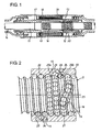
- Figure 1 shows an electric power steering device in the embodiment.
- a rack shaft (screw shaft) 11, a ball screw mechanism 12 and an electric motor 13 are assembled in a housing 10 which is mounted on a vehicle body (not shown) to be laid in the left-right direction of a vehicle.
- Lack teeth 14 are formed on a lateral surface at one end of the lack shaft 11 and are in meshing with a pinion (not shown) to which a steering force is transmitted from a steering handle (not shown).
- a pinion not shown
- the lack shaft 11 is moved in the axial direction thereof (i.e., the left-right direction as shown in Figure 1) thereby to steer steerable road wheels, e.g., front wheels (not shown).
- the lack shaft 11 has formed thereon a male screw groove 16 constituting the screw shaft 11 of the ball screw mechanism 12.
- the electric motor 13 is provided for supplying an axial assist force to the lack shaft 11 through the ball screw mechanism 12 and is composed of a rotor 17 and a stator 18.
- the rotor 17 takes the shape of an annular cylinder, and the rack shaft 11 extends through an annular bore of the rotor 17 in coaxial alignment.
- a plurality of plate-like permanent magnets 19 are secured on a circumferential surface of the rotor 17, and a stator 18 is arranged on an internal surface of the housing 10 to face the permanent magnets 19.
- the stator 18 is provided with plural coils, and thus, the rotor 17 is rotated by applying to the permanent magnets 19 the magnetic flux which is generated upon the application of an electric current to the coils.
- a nut 20 composing the aforementioned ball screw mechanism 12 is secured on the internal surface of the rotor 17 and is rotatable together with the rotor 17.
- the ball screw mechanism 12 for steering the steerable road wheels of a motor vehicle (not shown) through the lack shaft 11 is composed primarily of the lack shaft 11, the nut 20 and a plurality of balls 21.
- a male screw groove 16 and a female screw groove 22 along which the balls 21 are rolled are helically formed respectively on the lack shaft 11 and the nut 20.
- the male screw groove 16 and the female screw groove 22 are formed to take a Gothic arc shape in cross-section. In the Gothic arc shape, flanks of each groove are formed by two arcs which are different in their arc centers but are identical in curvature.
- elongate apertures (window portions) 15, each of which extends over adjoining groove segments or portions 23a, 23b in the axial direction of the female screw groove 22, are formed in the circumferential portions of the nuts 20 respectively at four angular positions which are different in ninety degrees (90°) from one another.
- ball circulation pieces 25 are fit respectively in the four elongate apertures 15 and each has formed thereon a circulation groove 24 bridging the adjoining groove portions 23a, 23b.
- the circulation groove 24 formed on each ball circulation piece 25 partly takes the form of a tunnel and guides the balls 21 as it wraps up the balls 21, so that the balls 21 are circulated by overleaping a screw thread 26 of the male screw groove 16 extending between the adjoining groove portions 23a, 23b.
- each of the balls 21 is circulated to be returned to the same groove segment or portion on the female screw groove 22 after one turn around the screw shaft 11.
- each ball 21 is relieved of the constraint by the male screw groove 16 and does not act to transfer any force between the screw shaft 11 and the nut 20.
- the circulation groove 24 is formed by a groove whose cross-section is formed by a single arc differently from the male screw groove 16 and the female screw groove 22.
- Figure 3 is a fragmentary plan view showing one of the joint areas (E) between the female screw groove 22 and the circulation groove 24 of each ball circulation piece 25 in an enlarged scale.
- An angle ( ⁇ ) that is made by two boundary lines (D) between a finished surface (B) and an unfinished surfaces (C) on the both franks of the female screw groove 22 is made to be an acute angle in order to eliminate a step at the joint (A) between the female screw groove 22 and the circulation groove 24.
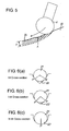
- a ball end mill (K) shown in Figures 4 and 5 which is equal to or larger in diameter than the balls 21 is employed in order to eliminate the step at the joint (A) between the female screw groove 22 and the circulation groove 24.
- the ball end mill (K) is moved along the female screw groove 22 (i.e., along the center line of the female screw groove 22) and is gradually increased in infeed depth as it goes toward the joint (A), whereby the angle ( ⁇ ) made by the boundary lines (D) becomes the acute angle.
- the end portion of the circulation groove 24 is slightly machined.
- the end portions of the female screw groove 22 and the circulation groove 24 which adjoin through each joint (A) therebetween can be machined as if they form a single groove surface having no step.
- Other joints (A) between each of other ball circulation pieces 25 and the female screw groove 22 are machined in the same manner as described above.
- each ball 21 reaches the joint (A) as the contact of each ball 21 with the female screw groove 22 is gradually changed from the two points (P) at the both flanks of the female screw groove 22 to the single point (P) at the bottom of the female screw groove 22, each ball 21 can move smoothly through the joint area (E) between the female screw groove 22 and the circulation groove 24.
- the boundary lines (D) between the finished surface (B) and the unfinished surface (C) on each end of the circulation groove 24 are formed to extend in a direction transverse to the circulation groove 24, as best shown in Figure 3.
- the transverse boundary lines (D) do not make a cause of generating vibration and noise because within the circulation groove 24, each ball 21 neither suffers constraint by the male screw groove 16 nor acts to transmit any screw feeding force.
- the cross-section of the female screw groove 22 is designed to take a Gothic arc shape, it is not limited to such a Gothic arc shape.
- the machining is performed by moving the ball end mill (K) from the female screw groove 22 toward the circulation groove 24.
- the machining order may be altered so that after being infed by the target infeed depth (t) within the circulation groove 24, the ball end mill (K) is moved toward the female screw groove 22 and is escaped from the female screw groove 22 by gradually decreasing the infeed depth from a position past the joint (A).
- the angle ( ⁇ ) made by the boundary lines (D) between the finished surface (B) and the unfinished surface (C) on the both flanks of the female screw groove 22 becomes an acute angle.
- each ball 21 when moving along the female screw groove 22, each ball 21 is contacted with the female screw groove 22 at the two contact points (P) because of the cross-section of the female screw groove 22 taking the Gothic arc shape, so that the stress exerted on the ball 21 can be bisected and so that the screw backlash can be diminished.
- the two contact points (P) of each ball 21 on the both flanks of the female screw groove 22 are made gradually narrower as each ball 21 approaches to the joint (A), and are converged into a single contract point (P).
- the delivery of each ball 21 within the joint area (E) between the female screw groove 22 and the circulation groove 24 can be done smoothly, so that it can be realized to prevent vibration and noise from being generated during the circulation of the balls 21.
- the ball screw mechanism 12 as constructed above is employed to prevent the generations of vibration and noise, so that the electric power steering device can be improved in the steering feeling given to the vehicle driver.
- the Gothic arc shape in the cross-section of the female screw groove 22 servers to bisect the stress exerted on the ball 21 and to diminish the screw backlash.
- the two contact points (P) of each ball 21 at the both flanks of the female screw groove 22 are made gradually narrower as each ball 21 approaches to the joint (A), and are converged into the single contract point (P).
- the delivery of each ball 21 within the joint area (E) between the female screw groove 22 and the ball circulation groove 24 can be done smoothly, so that it can be realized to prevent vibration and noise from being generated during the circulation of the balls 21.
- the acute angle ( ⁇ ) can be formed by the boundary lines (D) between the finished surface (B) and the unfinished surface (C) on the flanks of the female screw grooves 22.
- a ball end mill of the diameter equal to or larger than balls is moved along the female screw groove to machine a joint area between the respective one ends of the female screw groove and the circulation groove.
- the infeed depth of the ball end mill into the machined surface is gradually increased so that an acute angle is formed as the angle formed by the boundary lines between a finished surface and an unfinished surface at both flanks of the female screw groove.
Landscapes
- Engineering & Computer Science (AREA)
- Mechanical Engineering (AREA)
- General Engineering & Computer Science (AREA)
- Chemical & Material Sciences (AREA)
- Combustion & Propulsion (AREA)
- Transportation (AREA)
- Transmission Devices (AREA)
- Power Steering Mechanism (AREA)
- Milling Processes (AREA)
Abstract
Description
Claims (8)
- A ball screw mechanism comprising a screw shaft with a male screw groove formed on an external surface thereof; a nut with a female screw groove formed on an internal surface thereof; plural balls held in the male and female screw grooves of the screw shaft and the nut; and a ball circulation piece fit in a window portion formed in the nut and having a circulation groove formed thereon for circulating the balls;
wherein the female screw groove and the circulation groove are machined by moving a tool of a diameter equal to or larger than the diameter of the balls, along the female screw groove so that a step is eliminated at a joint between the female screw groove of the nut and the circulation groove of the ball circulation piece, and
wherein the infeed depth of the tool is gradually changed as the tool is moved toward the joint so that an acute angle is made by boundary lines between a finished surface and an unfinished surface on both flanks of the female screw groove. - The ball screw mechanism as set forth in Claim 1, wherein the cross-section of the female screw groove takes a Gothic arc shape.
- An electric power steering device incorporating a ball screw mechanism for steering steerable road wheels of a vehicle and an electric motor for operating the ball screw mechanism, the ball screw mechanism comprising a screw shaft with a male screw groove formed on an external surface thereof; a nut with a female screw groove formed on an internal surface thereof; plural balls held in the male and female screw grooves of the screw shaft and the nut; and a circulation piece fit in a window portion formed in the nut and having a circulation groove formed thereon for circulating the balls;
wherein the female screw groove and the circulation groove are machined by moving a tool of a diameter equal to or larger than the diameter of the balls, along the female screw groove so that a step is eliminated at a joint between the female screw groove of the nut and the circulation groove of the ball circulation piece, and by gradually changing the infeed depth of the tool as the tool is moved toward the joint so that an acute angle is made by boundary lines between a finished surface and an unfinished surface on both flanks of the female screw groove. - The electric power steering device as set forth in Claim 3, wherein the cross-section of the female screw groove takes a Gothic arc shape.
- A method of machining each of joints between a nut and a ball circulation piece secured to the same for use in a ball screw mechanism which comprises a screw shaft with a male screw groove formed on an external surface thereof; the nut with a female screw groove formed on an internal surface thereof; plural balls held in the male and female screw grooves of the screw shaft and the nut; and the ball circulation piece fit in a window portion formed in the nut and having a circulation groove formed thereon for circulating the balls;
the method comprising the steps of:providing a tool of a diameter equal to or larger than the diameter of the balls;positioning the tool at a machining start position in the female screw groove; andmoving the tool along the female screw groove to the circulation groove while gradually increasing the infeed depth of the tool to a target infeed depth, which is sufficient to eliminate a step at the joint between the female screw groove and the circulation groove, so that an acute angle is made by boundary lines between a finished surface and an unfinished surface on both flanks of the female screw groove. - The method as set forth in Claim 5, wherein the tool is a ball end mill.
- A method of machining each of joints between a nut and a ball circulation piece secured to the same for use in a ball screw mechanism which comprises a screw shaft with a male screw groove formed on an external surface thereof; the nut with a female screw groove formed on an internal surface thereof; plural balls held in the male and female screw grooves of the screw shaft and the nut; and the ball circulation piece fit in a window portion formed in the nut and having a circulation groove formed thereon for circulating the balls;
the method comprising the steps of:providing a tool of a diameter equal to or larger than the diameter of the balls;positioning the tool at a machining start position in the circulation groove;infeeding the tool into the ball circulation piece to a target infeed depth which is sufficient to eliminate a step at the joint between the female screw groove and the circulation groove;moving the tool from the circulation groove toward the female screw groove; andpast the joint between the circulation groove and the female screw groove, further moving the tool along the female screw while gradually decreasing the infeed depth of the tool until the tools is disengaged from the female screw groove so that an acute angle is made by boundary lines between a finished surface and an unfinished surface on both flanks of the female screw groove. - The method as set forth in Claim 7, wherein the tool is a ball end mill.
Applications Claiming Priority (2)
| Application Number | Priority Date | Filing Date | Title |
|---|---|---|---|
| JP2003353195A JP4483257B2 (en) | 2003-10-14 | 2003-10-14 | Method for processing joint of ball screw and its nut and electric power steering apparatus |
| JP2003353195 | 2003-10-14 |
Publications (3)
| Publication Number | Publication Date |
|---|---|
| EP1524171A2 true EP1524171A2 (en) | 2005-04-20 |
| EP1524171A3 EP1524171A3 (en) | 2010-07-07 |
| EP1524171B1 EP1524171B1 (en) | 2011-11-23 |
Family
ID=34373537
Family Applications (1)
| Application Number | Title | Priority Date | Filing Date |
|---|---|---|---|
| EP04023611A Expired - Lifetime EP1524171B1 (en) | 2003-10-14 | 2004-10-04 | Ball screw mechanism, machining method for joint between nut and ball circulation piece, and electric power steering device |
Country Status (4)
| Country | Link |
|---|---|
| US (1) | US7337689B2 (en) |
| EP (1) | EP1524171B1 (en) |
| JP (1) | JP4483257B2 (en) |
| CN (1) | CN100470089C (en) |
Cited By (1)
| Publication number | Priority date | Publication date | Assignee | Title |
|---|---|---|---|---|
| EP2392837A3 (en) * | 2010-06-07 | 2012-04-04 | JTEKT Corporation | Ball screw apparatus and electric power steering apparatus |
Families Citing this family (22)
| Publication number | Priority date | Publication date | Assignee | Title |
|---|---|---|---|---|
| DE102004025683A1 (en) * | 2004-05-26 | 2005-12-15 | Ina-Schaeffler Kg | Spindle nut for a ball screw drive |
| US7677126B2 (en) * | 2005-03-22 | 2010-03-16 | Gm Global Technology Operations, Inc. | Ball screw mechanism |
| JP5082852B2 (en) * | 2005-09-05 | 2012-11-28 | 日本精工株式会社 | Ball screw mechanism and ball screw assembly method |
| JP4640135B2 (en) * | 2005-11-24 | 2011-03-02 | トヨタ自動車株式会社 | Ball screw and ball screw nut manufacturing method |
| US7640821B2 (en) * | 2007-01-03 | 2010-01-05 | Hiwin Technologies Corp. | Circulating member for a ball screw |
| WO2009100332A2 (en) * | 2008-02-06 | 2009-08-13 | Trw Automotive U.S. Llc | Ball screw and nut assembly |
| TWI368697B (en) * | 2008-10-31 | 2012-07-21 | Hiwin Tech Corp | Circulation element for ball screw |
| CN102278440B (en) * | 2010-06-08 | 2014-03-05 | 朱豪东 | Ball screw cap with deep groove track and manufacturing method thereof |
| CN102367862B (en) * | 2010-11-25 | 2013-12-25 | 山东博特精工股份有限公司 | Linear roller guide rail pair inverter |
| DE102011076438B4 (en) * | 2011-05-25 | 2020-03-12 | Aktiebolaget Skf | Concept for a nut or spindle of a roller screw drive |
| FR2997326B1 (en) * | 2012-10-30 | 2015-04-17 | Skf Ab | METHOD OF MANUFACTURING THE THREADING OF A NUT NUT AND TAPPER NUT SYSTEM BY DEFORMATION THEREFOR |
| DE102014002286A1 (en) * | 2013-02-28 | 2014-08-28 | Mando Corporation | Recirculating Spindle Type Electric Power Steering Device |
| CN103148080B (en) * | 2013-03-12 | 2015-06-17 | 哈尔滨工业大学 | Unlockable nut in sandwich cantilever longitudinal vibration working mode |
| CN104395644A (en) * | 2013-06-05 | 2015-03-04 | 日本精工株式会社 | Ball screw |
| US10293848B2 (en) | 2014-12-03 | 2019-05-21 | Trw Automotive U.S. Llc | Rack ball nut assembly for a vehicle steering gear and related components thereof |
| JP6577195B2 (en) * | 2015-02-04 | 2019-09-18 | Ntn株式会社 | Koma-type ball screw manufacturing method |
| KR102349870B1 (en) | 2015-07-20 | 2022-01-11 | 주식회사 만도 | Rack Assist Type Power Steering Apparatus |
| DE102015214859B4 (en) * | 2015-08-04 | 2017-12-14 | Schaeffler Technologies AG & Co. KG | Ball Screw |
| WO2019133855A1 (en) * | 2017-12-29 | 2019-07-04 | Kelsey-Hayes Company | Ball nut assembly |
| US11655885B2 (en) * | 2019-12-06 | 2023-05-23 | Pacific Bearing Corp. | Multiliner for multiple start ball nut threads |
| CN113441911B (en) * | 2021-06-23 | 2024-07-09 | 陕西德臻零部件科技有限公司 | Integrated processing method of internal circulation steering nut |
| US20240391518A1 (en) * | 2023-05-23 | 2024-11-28 | Ford Global Technologies, Llc | Steering gears with electric steering assist systems and related methods |
Family Cites Families (6)
| Publication number | Priority date | Publication date | Assignee | Title |
|---|---|---|---|---|
| US4177690A (en) * | 1978-02-22 | 1979-12-11 | Beaver Precision Products, Inc. | Ball screw and nut |
| IT1219011B (en) * | 1988-02-11 | 1990-04-24 | Roltra Spa | BALL MOTOR SCREW COUPLING |
| JPH03181649A (en) * | 1989-12-12 | 1991-08-07 | Mitsubishi Heavy Ind Ltd | Ball screw |
| JPH10141465A (en) * | 1996-11-07 | 1998-05-29 | Nippon Seiko Kk | Ball screw device embedded in ball circulation section |
| JP4026922B2 (en) | 1998-03-23 | 2007-12-26 | 株式会社ショーワ | Chamfering method for window with built-in deflector of nut screw |
| US6736235B2 (en) * | 2000-11-29 | 2004-05-18 | Ntn Corporation | Powered steering device and ball screw mechanism therefor |
-
2003
- 2003-10-14 JP JP2003353195A patent/JP4483257B2/en not_active Expired - Fee Related
-
2004
- 2004-10-01 US US10/954,174 patent/US7337689B2/en not_active Expired - Fee Related
- 2004-10-04 EP EP04023611A patent/EP1524171B1/en not_active Expired - Lifetime
- 2004-10-13 CN CN200410085555.7A patent/CN100470089C/en not_active Expired - Fee Related
Cited By (2)
| Publication number | Priority date | Publication date | Assignee | Title |
|---|---|---|---|---|
| EP2392837A3 (en) * | 2010-06-07 | 2012-04-04 | JTEKT Corporation | Ball screw apparatus and electric power steering apparatus |
| US8505405B2 (en) | 2010-06-07 | 2013-08-13 | Jtekt Corporation | Ball screw apparatus and electric power steering apparatus |
Also Published As
| Publication number | Publication date |
|---|---|
| EP1524171A3 (en) | 2010-07-07 |
| CN1607342A (en) | 2005-04-20 |
| JP4483257B2 (en) | 2010-06-16 |
| US20050076733A1 (en) | 2005-04-14 |
| JP2005121042A (en) | 2005-05-12 |
| EP1524171B1 (en) | 2011-11-23 |
| CN100470089C (en) | 2009-03-18 |
| US7337689B2 (en) | 2008-03-04 |
Similar Documents
| Publication | Publication Date | Title |
|---|---|---|
| EP1524171B1 (en) | Ball screw mechanism, machining method for joint between nut and ball circulation piece, and electric power steering device | |
| US6736235B2 (en) | Powered steering device and ball screw mechanism therefor | |
| JP4371430B2 (en) | Ball screw device with circulation path and method of manufacturing the same | |
| JP5255503B2 (en) | Rolling element screw device | |
| US10683918B2 (en) | Ball screw device and steering system including ball screw device | |
| US20170008555A1 (en) | Power steering device and method for manufacturing ball screw for power steering device | |
| EP3255308B1 (en) | Ball screw mechanism and steering system | |
| CN101939566A (en) | Ball screw and nut assembly | |
| US20180100566A1 (en) | Ball screw device, method of manufacturing ball screw device, and steering system | |
| KR20070011452A (en) | Screw device and its manufacturing method | |
| KR101845182B1 (en) | Power steering device and method for manufacturing power steering device | |
| US9377092B2 (en) | Ball screw deflector | |
| JP2019086068A (en) | Ball screw device and steering device | |
| US7322256B2 (en) | Ball screw mechanism for electric power steering apparatus | |
| JP6984327B2 (en) | Ball screw device and steering device | |
| EP3922885B1 (en) | Ball screw device | |
| WO2023188058A1 (en) | Ball screw device | |
| JP2007024229A (en) | Ball screw device, manufacturing method thereof, and electric power steering apparatus using the ball screw device | |
| KR20220120823A (en) | Rack-Driven Power Assisted Steering | |
| JP2008064250A (en) | Deflector ball screw device | |
| JP4679451B2 (en) | Ball screw for automobile | |
| KR20250073183A (en) | Ball screw | |
| JP2000297855A (en) | Electric power steering device | |
| JP2006342866A (en) | Ball screw device and electric power steering device | |
| JP2008101748A (en) | Ball screw device |
Legal Events
| Date | Code | Title | Description |
|---|---|---|---|
| PUAI | Public reference made under article 153(3) epc to a published international application that has entered the european phase |
Free format text: ORIGINAL CODE: 0009012 |
|
| AK | Designated contracting states |
Kind code of ref document: A2 Designated state(s): AT BE BG CH CY CZ DE DK EE ES FI FR GB GR HU IE IT LI LU MC NL PL PT RO SE SI SK TR |
|
| AX | Request for extension of the european patent |
Extension state: AL HR LT LV MK |
|
| RAP1 | Party data changed (applicant data changed or rights of an application transferred) |
Owner name: TOYODA KOKI KABUSHIKI KAISHA Owner name: JTEKT CORPORATION Owner name: FAVESS CO., LTD. |
|
| RAP1 | Party data changed (applicant data changed or rights of an application transferred) |
Owner name: JTEKT CORPORATION |
|
| PUAL | Search report despatched |
Free format text: ORIGINAL CODE: 0009013 |
|
| AK | Designated contracting states |
Kind code of ref document: A3 Designated state(s): AT BE BG CH CY CZ DE DK EE ES FI FR GB GR HU IE IT LI LU MC NL PL PT RO SE SI SK TR |
|
| AX | Request for extension of the european patent |
Extension state: AL HR LT LV MK |
|
| 17P | Request for examination filed |
Effective date: 20100721 |
|
| RIN1 | Information on inventor provided before grant (corrected) |
Inventor name: SUGITA, SENTAROU Inventor name: YAMAMOTO, YASUHARU |
|
| AKX | Designation fees paid |
Designated state(s): DE FR GB |
|
| GRAP | Despatch of communication of intention to grant a patent |
Free format text: ORIGINAL CODE: EPIDOSNIGR1 |
|
| RIC1 | Information provided on ipc code assigned before grant |
Ipc: B62D 5/04 20060101AFI20110321BHEP Ipc: F16H 25/22 20060101ALI20110321BHEP |
|
| RIN1 | Information on inventor provided before grant (corrected) |
Inventor name: YAMAMOTO, YASUHARU Inventor name: SUGITA, SENTAROU |
|
| GRAS | Grant fee paid |
Free format text: ORIGINAL CODE: EPIDOSNIGR3 |
|
| RIN1 | Information on inventor provided before grant (corrected) |
Inventor name: YAMAMOTO, YASUHARU,C/O FAVESS CO., LTD. Inventor name: SUGITA, SENTAROU,C/O FAVESS CO., LTD. |
|
| GRAA | (expected) grant |
Free format text: ORIGINAL CODE: 0009210 |
|
| AK | Designated contracting states |
Kind code of ref document: B1 Designated state(s): DE FR GB |
|
| REG | Reference to a national code |
Ref country code: GB Ref legal event code: FG4D |
|
| REG | Reference to a national code |
Ref country code: DE Ref legal event code: R096 Ref document number: 602004035380 Country of ref document: DE Effective date: 20120202 |
|
| PLBE | No opposition filed within time limit |
Free format text: ORIGINAL CODE: 0009261 |
|
| STAA | Information on the status of an ep patent application or granted ep patent |
Free format text: STATUS: NO OPPOSITION FILED WITHIN TIME LIMIT |
|
| 26N | No opposition filed |
Effective date: 20120824 |
|
| REG | Reference to a national code |
Ref country code: DE Ref legal event code: R097 Ref document number: 602004035380 Country of ref document: DE Effective date: 20120824 |
|
| GBPC | Gb: european patent ceased through non-payment of renewal fee |
Effective date: 20121004 |
|
| PG25 | Lapsed in a contracting state [announced via postgrant information from national office to epo] |
Ref country code: GB Free format text: LAPSE BECAUSE OF NON-PAYMENT OF DUE FEES Effective date: 20121004 |
|
| REG | Reference to a national code |
Ref country code: FR Ref legal event code: PLFP Year of fee payment: 13 |
|
| REG | Reference to a national code |
Ref country code: FR Ref legal event code: PLFP Year of fee payment: 14 |
|
| REG | Reference to a national code |
Ref country code: FR Ref legal event code: PLFP Year of fee payment: 15 |
|
| PGFP | Annual fee paid to national office [announced via postgrant information from national office to epo] |
Ref country code: FR Payment date: 20200914 Year of fee payment: 17 |
|
| PGFP | Annual fee paid to national office [announced via postgrant information from national office to epo] |
Ref country code: DE Payment date: 20200922 Year of fee payment: 17 |
|
| REG | Reference to a national code |
Ref country code: DE Ref legal event code: R119 Ref document number: 602004035380 Country of ref document: DE |
|
| PG25 | Lapsed in a contracting state [announced via postgrant information from national office to epo] |
Ref country code: DE Free format text: LAPSE BECAUSE OF NON-PAYMENT OF DUE FEES Effective date: 20220503 |
|
| PG25 | Lapsed in a contracting state [announced via postgrant information from national office to epo] |
Ref country code: FR Free format text: LAPSE BECAUSE OF NON-PAYMENT OF DUE FEES Effective date: 20211031 |