EP1524149A1 - Tensioning device for fastening goods on a truck - Google Patents
Tensioning device for fastening goods on a truck Download PDFInfo
- Publication number
- EP1524149A1 EP1524149A1 EP04008264A EP04008264A EP1524149A1 EP 1524149 A1 EP1524149 A1 EP 1524149A1 EP 04008264 A EP04008264 A EP 04008264A EP 04008264 A EP04008264 A EP 04008264A EP 1524149 A1 EP1524149 A1 EP 1524149A1
- Authority
- EP
- European Patent Office
- Prior art keywords
- pawl
- main frame
- plate
- axle
- lever
- Prior art date
- Legal status (The legal status is an assumption and is not a legal conclusion. Google has not performed a legal analysis and makes no representation as to the accuracy of the status listed.)
- Granted
Links
- 238000007373 indentation Methods 0.000 claims description 21
- 238000012986 modification Methods 0.000 description 1
- 230000004048 modification Effects 0.000 description 1
Images


Classifications
-
- B—PERFORMING OPERATIONS; TRANSPORTING
- B60—VEHICLES IN GENERAL
- B60P—VEHICLES ADAPTED FOR LOAD TRANSPORTATION OR TO TRANSPORT, TO CARRY, OR TO COMPRISE SPECIAL LOADS OR OBJECTS
- B60P7/00—Securing or covering of load on vehicles
- B60P7/06—Securing of load
- B60P7/08—Securing to the vehicle floor or sides
- B60P7/0823—Straps; Tighteners
- B60P7/083—Tensioning by repetetive movement of an actuating member
-
- Y—GENERAL TAGGING OF NEW TECHNOLOGICAL DEVELOPMENTS; GENERAL TAGGING OF CROSS-SECTIONAL TECHNOLOGIES SPANNING OVER SEVERAL SECTIONS OF THE IPC; TECHNICAL SUBJECTS COVERED BY FORMER USPC CROSS-REFERENCE ART COLLECTIONS [XRACs] AND DIGESTS
- Y10—TECHNICAL SUBJECTS COVERED BY FORMER USPC
- Y10T—TECHNICAL SUBJECTS COVERED BY FORMER US CLASSIFICATION
- Y10T24/00—Buckles, buttons, clasps, etc.
- Y10T24/21—Strap tighteners
- Y10T24/2102—Cam lever and loop
- Y10T24/2104—Step adjusted
- Y10T24/2113—Strap tighteners
-
- Y—GENERAL TAGGING OF NEW TECHNOLOGICAL DEVELOPMENTS; GENERAL TAGGING OF CROSS-SECTIONAL TECHNOLOGIES SPANNING OVER SEVERAL SECTIONS OF THE IPC; TECHNICAL SUBJECTS COVERED BY FORMER USPC CROSS-REFERENCE ART COLLECTIONS [XRACs] AND DIGESTS
- Y10—TECHNICAL SUBJECTS COVERED BY FORMER USPC
- Y10T—TECHNICAL SUBJECTS COVERED BY FORMER US CLASSIFICATION
- Y10T24/00—Buckles, buttons, clasps, etc.
- Y10T24/21—Strap tighteners
- Y10T24/2102—Cam lever and loop
- Y10T24/2117—Strap tighteners
Definitions
- the present invention relates to a belt reel, and more particularly to a belt reel for fastening goods on a truck.
- the belt reel can certainly release the strain of the belt step by step.
- a conventional belt reel assembly for fastening goods on a truck in accordance with the prior art shown in Figs. 13-16 comprises main frame (81), a lever (82) and an axle (83) laterally extending through the main frame (81) and the lever (82) for pivotally mounting the main frame (81) an the lever (82) to each other.
- Two ratchets (84) are respectively mounted to two opposite ends of the axle (83) and rotated with the axle (83).
- the lever (82) includes a pawl (821) slidably mounted therein.
- the main frame (81) has an indentation (811) defined therein and corresponds to the pawl (821), and a concave portion (812) defined adjacent to the indentation (811).
- a stopper (813) extends from the main frame (81) between the indentation (811) and the concave portion (812).
- the main frame (81) has a stop plate (814) slidably mounted in the main frame (81) and engaged to the two ratchets (84).
- the lever (82) has a convex (822) extending therefrom and corresponding to the stop plate (814).
- the convex portion (822) of the lever (82) backward pushes and makes the stop plate (814) be disengaged to the ratchet (84) when the pawl (821) is moved within the indentation (811).
- the axle (83) and the ratchets (84) are in a free condition so that the belt (85) is released due to the strain of the strained belt (85).
- the tooth of the ratchet (84) is moved over the pawl (821) and the stop plate (814) engaged to the ratchet (84) again when the pawl (821) is move to the guiding side (815) of the indentation (811) and the convex portion (822) of the lever (82) is separated from the stop plate (814). Consequently, the ratchet (84) is only rotated about one pitch of the teeth of the ratchet (84) when releasing the strain of the strained belt (85) step by step.
- the strained belt (85) usually contains a great strain and the stop plate (814) is securely engaged to the ratchet (84) so that the operator needs to laboriously pull the lever (82) to make the convex (822) thereof backward push the stop plate (814).
- the great strain of the strained belt (5) speedily rotates the ratchet (84) and drives the pawl (821) moved to the guiding side (815).
- the operator hardly stops exerting force because the pawl (821) is moved to the guiding side (815) in moment.
- the operator usually continually exerts force to pull the lever (82) so that the convex portion (822) may backward push the stop plate (814) again. Consequently, the ratchet (84) is rotated more than one pitch thereof and the strain of the strained belt (85) may not be released step by step.
- the pawl (821) is moved to be partially received in the second indentation (816), and the axle (83) and ratchet (84) is in a free condition after the strain of the strained belt (85) being fully released and then the operator can easily pull the belt (85) from the conventional belt reel.
- the operator needs to continually pull the pawl (821) when moving the pawl (821) toward the second indentation (816). It is a laborious design and inconvenient operated.
- the present invention has arisen to mitigate and/or obviate the disadvantages of the conventional belt reel for fastening goods on a truck.
- the main objective of the present invention is to provide an improved belt reel for fastening goods on a truck.
- the belt reel of the present invention can certainly release the strain of the belt step by step.
- the belt reel in accordance with the present invention comprises an axle extending through a main frame and a lever to pivotally mount the main frame and the lever to each other.
- the axle includes two opposite ends each having a ratchet wheel mounted thereto between the main frame and the lever and rotated with the axle.
- Each ratchet wheel has a series of teeth radially extending therefrom and a slot is diametrically defined in the axle for allowing a belt extending through the axle.
- the main frame includes a stop plate slidably mounted therein and a spring compressively mounted between the main frame and the stop plate so that the stop plate is engaged to the two ratchet wheels due to a restitution force of the spring.
- the lever includes a pawl slidably mounted therein and a resilient member is mounted between the lever and the pawl so that the pawl is selective engaged to the two ratchet wheels due to a restitution force of the resilient member.
- the lever includes a pivot portion having two opposite sides each having a convex portion extending from the lever and corresponding to the two opposite sides of the stop plate.
- the main frame includes a pivot end having two opposite sides each sequentially having a concave portion defined in the main frame, a stopper extending from the main frame, a groove defined in the main frame, an indentation defined in the main frame and a connecting portion formed between the groove and the indentation.
- the groove includes a first side formed adjacent to the stopper and a second side formed adjacent to the connecting portion.
- the convex portion backward pushes the stop plate to make the stop plate disengaged from the ratchet wheels when the pawl abuts the second side of the groove.
- the convex portion backward pushes the stop plate to make the stop plate disengaged from the ratchet wheels and the pawl is disengaged from the ratchet wheels when the pawl is partially received in the indentation.
- Two plates are respectively pivotally mounted to two opposite sides of the main frame. Each plate has a cam portion extending therefrom to the groove.
- the cam portion is tapered and has a first guide side and a second guide side.
- the cam portion makes the pawl moved over the series of teeth of each of the ratchet wheels.
- Each plate is positioned when the pawl is moved over the cam portion.
- the pawl is moved along the first guide side when the pawl is moved within the groove toward the second side of the groove.
- the pawl is firstly clamped between one tooth of the each of the ratchet wheels and the cam portion and secondarily moved over the cam portion along the second guide side when the pawl is moved within the groove toward the first side of the groove due to a reverse ratchet.
- a protrusion extends from each of the connecting portion toward the stopper. The protrusion extends through the pawl when the pawl is moved toward the second side of the groove and abuts the protrusion that guides the pawl to the indentation.
- a belt reel for fastening goods on a truck in accordance with the present invention comprises an axle (3) extending through a main frame (1) and a lever (2) to pivotally mount the main frame (1) and the lever (2) to each other.
- the axle (32) has two opposite ends each having a ratchet wheel (4) mounted thereto between the main frame (1) and the lever (2) and rotated with the axle (3).
- a slot (31) is diametrically defined in the axle (3) for allowing a belt (5) extending through the axle (3).
- the ratchet wheel (4) has a series of teeth (41) radially extending from a periphery of each of the ratchet wheels (4).
- the main frame (1) includes a stop plate (11) slidably mounted therein and a spring (12) compressively mounted between the main frame (1) and the stop plate (11) so that the stop plate (11) is engaged to the ratchet wheels (4) due to a restitution force of the spring (12).
- the lever (2) includes a pawl (21) slidably mounted in the lever and corresponding to the two ratchet wheels (4).
- a resilient member (23) is compressively mounted between the lever (2) and the pawl (21) so that the pawl (21) is selectively engaged to the two ratchet wheels (4) due to the restitution force of the resilient member (23).
- the pivot portion of the lever (2) includes two opposite sides each having a convex portion (22) extending therefrom and corresponding to the two opposite sides of the stop plate (11).
- the pivot end of the main frame (1) includes two opposite sides each sequentially having a concave portion (13) defined in the main frame (1), a stopper (14) extending from the main frame (1), a groove (15) defined in the main frame (1), an indentation (17) defined in the main frame (1) and a connecting portion (16) formed between the groove (15) and the indentation (17).
- the groove ( 15) has a first side (151) formed adjacent to the stopper (14) and a second side (152) formed adjacent to the connecting portion (16).
- the convex portion (22) backward pushes the stop plate (11) to make the stop plate (11) be disengaged from the ratchet wheels (4) when the pawl (21) abuts the second side (152) of the groove (15).
- the convex portion (22) backward pushes the stop plate (11) to make the stop plate (11) be disengaged from the ratchet wheels (4) and the pawl (21) is disengaged from the ratchet wheels (4) when the pawl (21) is partially received in the indentation (17).
- Each plate (6) is respectively pivotally mounted to two opposite ends of the axle (3) between the main frame (1) and the lever (2).
- Each plate (6) has a cam portion (61) extending therefrom to the groove (15).
- the cam portion (61) is tapered and has a first guide side (611) and a second guide side (612).
- the cam portion (61) makes the pawl (21) be moved over the one teeth (41) of the ratchet wheel (4) when moving along the second guide side (612).
- Each plate (6) includes a first stopper (62) and a second stopper (63) respectively extending therefrom opposite to the cam portion (61) and the stop plate (11) is located between the first stopper (62) and the second stopper (63) to prevent the plate (6) from being overly rotated.
- the pawl (21) pulls the plate (6) to make the second stopper (63) abut the stop plate (11) and is moved over one of the teeth (41) of the ratchet wheel (4) along the first guide side (611) when the pawl (21) is moved within the groove (15) toward the second side (152) of the groove (15).
- the pawl (21) is firstly clamped between the tooth (41) and the cam portion (61) and secondarily moved over the cam portion (61) along the second guide side (612) when the pawl (21) is moved within the groove (15) toward the first side (151) of the groove (15) due to the reverse ratchet (4).
- a protrusion (18) extends from each of the connecting portion (16) toward the stopper (14).
- the protrusion (18) is curved.
- the pawl (21) has a cutout (211) defined therein for allowing the protrusion (18) extending through the pawl (21) when the pawl (21) is moved toward the second side (152) of the groove (15).
- the pawl (21) abuts the protrusion (18) that guides the pawl (21) to the indentation (17).
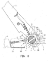
- the pawl (21) When releasing the strained belt (5), the pawl (21) is backward pulled and the lever (2) is pivotally moved relative to the main frame (1). The pawl (21) is released to abut the first guide side (611) of the plate (6) when the pawl (21) is moved over the stopper (14), as shown in Fig. 4. With reference to Fig. 5, to continually move the lever (2), the pawl (21) pushes the plate (6) to make the second stopper (63) abut the stop plate (11), then the pawl (21) is moved over the tooth (41) along the first guide side (611) of the plate (6). The protrusion (18) extends through the cutout (211) when the pawl (21) moved within the groove (15). With reference to Fig.
- the convex (22) of the lever (2) backward pushes the stop plate (11) to make the stop plate (11) be disengaged from the ratchet wheel (4) and the axle (3) with the ratchet wheels (4) are rotated to release the belt (5) due to the strain of the strained belt (5) when the pawl (21) is moved to abut the second side (152) of the groove (15).
- the tooth (41) pushes the pawl (21) with the lever (2) moved toward the first side (151) of the groove (15) to make the convex portion (22) be separated from the stop plate (11) so that the stop plate (11) engaged to the ratchet wheels (4) again when the ratchet wheels (4) is rotated due to the strain of the strained belt (5).
- the belt reel in accordance with the present invention released the strained belt (5) only in a distance each time and the released distance is equal to the pitch of the teeth (41) of each of the ratchet wheels (4) as shown in Fig. 7.
- the axle (3) will strain the belt (5) again when pulling the lever (2) because the pawl (21) is engaged to the ratchet wheels (4) when pulling the lever (2).
- the belt (5) restores the original strain before pulling the lever (2) when the convex portion (22) backward pushes the stop plate (11) again. Consequently, the belt reel of the present invention certainly releases the strain of the strained belt (5) step by step.
- the operator For fully releasing the strain of the strained belt (5), the operator needs to pull pawl (21) and make the pawl (21) moved over the cam portion (61) along the second guide side (612) of the plate (6), then the relation between the elements of the present invention is shown in Fig. 4. To repeat the above steps, the strain of the strained belt (5) is certainly released step by step.
- the operator can pull the pawl (21) and move the lever (2) to make the pawl (21) abut the protrusion (18) when the strain of the strained belt (5) is fully released.
- the pawl (21) is moved along the protrusion (18) and the protrusion (18) guides the pawl (21) moved into the indentation (17) when continually moving the lever (2).
- the operator can easily draw the belt (5) out of the belt reel when the pawl (21) is partially received in the indentation (17) and the stop plate (11) is separated from the ratchet wheels (4) due to the convex portion (22) of the lever (2) because the axle (3) and the ratchet wheels (4) are in a free condition.
- the main frame (1A) includes two arc slots (19A) respectively defined in two opposite sides of the main frame (1A) near the axle (3A).
- the curvature of each of the arc slots (19A) concentrically corresponds to the axle (3A).
- Each plate (6A) has a stub (62A) laterally extending therefrom and slidably received in a corresponding one of the two arc slots (19A) in the main frame (1A) to prevent the plate (6A) from being overly rotated.
- the two plates (6B) are respectively pivotally mounted to the main frame (1B) near the groove (15B).
- the main frame (1B) includes two arc slots (19B) respectively defined in two opposite sides of the main frame (1A) corresponding to a lower end of each of the two plates (6B).
- Each plate (6B) has a stub (62B) laterally extending therefrom and slidably received in a corresponding one of the two arc slots (19B) in the main frame (1B) to prevent the plate (6B) from being overly rotated.
- the pawl (21 C) includes an opening (211 C) defined therein and corresponding to the protrusion (18C) such that the protrusion (18C) extends through the pawl (21C) when the lever is pulled.
- a belt reel for fastening goods on a truck includes an axle (3) extending through a main frame (1) and a lever (2) to pivotally mount the main frame (1) and the lever (2) to each other.
- the axle (3) includes two opposite ends each having a ratchet wheel (4) mounted thereto between the main frame (1) and the lever (2) and rotated with the axle (3).
- a slot (31) is diametrically defined in the axle (3) for allowing a belt (5) extending through the axle (3).
- the main frame (1) has a stop plate (11) slidably mounted therein and selectively engaged to the ratchet wheels (4), and the lever (2) has a pawl (21) slidably mounted therein. The pawl (21) is engaged to the ratchet wheels (4) for driving the axle (3) to reel the belt (5) and separated from the ratchet wheels (4) for releasing the strain of the strained belt.
Abstract
Description
Claims (10)
- A belt reel for fastening goods on a truck, comprising an axle extending through a main frame and a lever to pivotally mount the main frame and the lever to each other, the axle having two opposite ends each having a ratchet wheel mounted thereto between the main frame and the lever and rotated with the axle, each ratchet wheel having a series of teeth radially extending therefrom, a slot diametrically defined in the axle for allowing a belt extending through the axle, the main frame including a stop plate slidably mounted therein and a spring compressively mounted between the main frame and the stop plate so that the stop plate is engaged to the two ratchet wheels due to a restitution force of the spring, the lever including a pawl slidably mounted therein and a resilient member mounted between the lever and the pawl so that the pawl is selective engaged to the two ratchet wheels due to a restitution force of the resilient member, the lever including a pivot portion having two opposite sides each having a convex portion extending from the lever and corresponding to the two opposite sides of the stop plate, the main frame includes a pivot end having two opposite sides each sequentially having a concave portion defined in the main frame, a stopper extending from the main frame, a groove defined in the main frame, an indentation defined in the main frame and a connecting portion formed between the groove and the indentation, the groove including a first side formed adjacent to the stopper and a second side formed adjacent to the connecting portion, the convex portion backward pushing the stop plate to make the stop plate disengaged from the ratchet wheels when the pawl abuts the second side of the groove, the convex portion backward pushing the stop plate to make the stop plate disengaged from the ratchet wheels and the pawl disengaged from the ratchet wheels when the pawl is partially received in the indentation;
wherein the improvement comprises:two plates respectively pivotally mounted to two opposite sides of the main frame, each plate having a cam portion extending therefrom to the groove, the cam portion being tapered and having a first guide side and a second guide side, the cam portion making the pawl moved over the series of teeth of each of the ratchet wheels, each plate being positioned when the pawl is moved over the cam portion, the pawl moved along the first guide side when the pawl is moved within the groove toward the second side of the groove, the pawl firstly clamped between one tooth of the each of the ratchet wheels and the cam portion and secondarily moved over the cam portion along the second guide side when the pawl is moved within the groove toward the first side of the groove due to a reverse ratchet; anda protrusion extending from each of the connecting portion toward the stopper, the protrusion extending through the pawl when the pawl is moved toward the second side of the groove and abuts the protrusion that guides the pawl to the indentation. - The belt reel as claimed in claim 1, wherein each plate comprises a first stopper and a second stopper respectively extending therefrom opposite to the cam portion and the stop place is located between the first stopper and the second stopper to prevent the plate from being overly rotated and selectively hold the plate in place when the pawl is moved over the cam portion.
- The belt reel as claimed in claim 1, wherein the main frame comprises two arc slot respectively defined in two opposite sides of the main frame near the axle, and each plate comprises a stub laterally extending therefrom and slidably received in a corresponding one of the two arc in the main frame to prevent the plate from being overly rotated and selectively hold the plate in place when the pawl is moved over the cam portion.
- The belt reel as claimed in claim 1, wherein the two plates are respectively mounted to two opposite ends of the axle and the main frame comprises two arc slot respectively defined in two opposite sides of the main frame near the axle, a curvature of each of the arc slots concentrically corresponding to the axle, each plate including a stub laterally extending therefrom and slidably received in a corresponding one of the two arc in the main frame to prevent the plate from being overly rotated and selectively hold the plate in place when the pawl is moved over the cam portion.
- The belt reel as claimed in claim 2, wherein the main frame comprises two arc slot respectively defined in two opposite sides of the main frame near the axle, and each plate comprises a stub laterally extending therefrom and slidably received in a corresponding one of the two arc in the main frame to prevent the plate from being overly rotated and selectively hold the plate in place when the pawl is moved over the cam portion.
- The belt reel as claimed in claim 2, wherein the two plates are respectively mounted to two opposite ends of the axle and the main frame comprises two arc slot respectively defined in two opposite sides of the main frame near the axle, a curvature of each of the arc slots concentrically corresponding to the axle, each plate including a stub laterally extending therefrom and slidably received in a corresponding one of the two arc in the main frame to prevent the plate from being overly rotated and selectively hold the plate in place when the pawl is moved over the cam portion.
- The belt reel as claimed in claim 5, wherein the pawl comprises a cutout defined therein for allowing the protrusion extending through the pawl.
- The belt reel as claimed in claim 5, wherein the pawl comprises an opening defined therein for allowing the protrusion extending through the pawl.
- The belt reel as claimed in claim 6, wherein the pawl comprises a cutout defined therein for allowing the protrusion extending through the pawl.
- The belt reel as claimed in claim 6, wherein the pawl comprises an opening defined therein for allowing the protrusion extending through the pawl.
Applications Claiming Priority (2)
| Application Number | Priority Date | Filing Date | Title |
|---|---|---|---|
| US684193 | 2000-10-06 | ||
| US10/684,193 US6880810B1 (en) | 2003-10-14 | 2003-10-14 | Belt reel assembly for fastening goods on a truck |
Publications (2)
| Publication Number | Publication Date |
|---|---|
| EP1524149A1 true EP1524149A1 (en) | 2005-04-20 |
| EP1524149B1 EP1524149B1 (en) | 2006-07-12 |
Family
ID=34377600
Family Applications (1)
| Application Number | Title | Priority Date | Filing Date |
|---|---|---|---|
| EP04008264A Expired - Lifetime EP1524149B1 (en) | 2003-10-14 | 2004-04-05 | Tensioning device for fastening goods on a truck |
Country Status (4)
| Country | Link |
|---|---|
| US (1) | US6880810B1 (en) |
| EP (1) | EP1524149B1 (en) |
| AT (1) | ATE332822T1 (en) |
| DE (1) | DE602004001499T2 (en) |
Cited By (4)
| Publication number | Priority date | Publication date | Assignee | Title |
|---|---|---|---|---|
| GB2448150A (en) * | 2007-04-03 | 2008-10-08 | Kwang-Wang Liu | Belt tightener with removable roll sector |
| DE102010002052A1 (en) | 2009-06-15 | 2010-12-16 | Innoform Ag | Tensioning strap and fastening device for such a tension belt |
| CN101301935B (en) * | 2007-05-08 | 2011-07-13 | 黄汉卿 | Pulling ware capable of easily winding and unwinding strapping |
| DE202017003206U1 (en) | 2017-06-17 | 2017-12-15 | Marc Hoffmann | securing clamps |
Families Citing this family (28)
| Publication number | Priority date | Publication date | Assignee | Title |
|---|---|---|---|---|
| US6966543B2 (en) * | 2002-12-13 | 2005-11-22 | Tom Loudamy | Tie-down rewind tool |
| US7069623B2 (en) * | 2004-08-24 | 2006-07-04 | Rachet Co., Ltd | Tying device |
| US7377484B1 (en) * | 2006-06-02 | 2008-05-27 | Marcus Williams | Multi-functional ratchet and associated method |
| US20080104811A1 (en) * | 2006-11-08 | 2008-05-08 | Burrows Ward C | Tension limited ratchet buckle for securing cargo |
| US7293760B1 (en) * | 2007-01-10 | 2007-11-13 | Vincent Chang | Cable tightening device operated conveniently |
| US20080178439A1 (en) * | 2007-01-30 | 2008-07-31 | Han-Ching Huang | Strap-tightening apparatus |
| US7464915B2 (en) * | 2007-04-05 | 2008-12-16 | Kwang Wang Liu | Binding device |
| US8002242B2 (en) * | 2008-11-20 | 2011-08-23 | Jung-Wen Lu | Extension rod unit |
| US7845621B1 (en) * | 2009-08-18 | 2010-12-07 | Jung-Wen Lu | Tightener for a binding strap |
| US8157245B2 (en) * | 2009-09-21 | 2012-04-17 | Han-Ching Huang | Ratchet tie-down and reinforcement assembly |
| FR2952878B1 (en) * | 2009-11-25 | 2013-02-15 | Joubert Productions | TENSIONER DEVICE FOR STRAPS |
| US8209821B1 (en) * | 2009-12-18 | 2012-07-03 | Weiguo Chen | Lockable ratchet buckle |
| USD675498S1 (en) | 2010-06-18 | 2013-02-05 | Master Lock Company Llc | Ratchet |
| CN103889784A (en) * | 2011-03-07 | 2014-06-25 | 安克拉国际有限责任公司 | Strap tensioning system |
| US9725029B2 (en) * | 2011-03-15 | 2017-08-08 | The Ratchet Depot, Inc. | Ratchet strap tightener |
| USD681411S1 (en) | 2011-08-30 | 2013-05-07 | Master Lock Company Llc | Ratchet lock |
| GB201117251D0 (en) * | 2011-10-05 | 2011-11-16 | Autochair Ltd | Hoist mechanism |
| US20130326847A1 (en) * | 2012-06-12 | 2013-12-12 | Mei-Yu Zheng | Strap-Tensioning Apparatus |
| US9061622B2 (en) * | 2012-09-05 | 2015-06-23 | Ancra International Llc | Strap tensioning system |
| US9027709B2 (en) | 2013-01-09 | 2015-05-12 | Advanced Treestand Investments, LLC | Modular tree stand |
| US20150128388A1 (en) * | 2013-11-11 | 2015-05-14 | Cory Mastbeth | Binding apparatus, method and system |
| US9771014B2 (en) | 2014-02-07 | 2017-09-26 | Raymond Brown | Step release tension assembly |
| US9446704B1 (en) * | 2015-03-31 | 2016-09-20 | David Gramenz | Tie down |
| USD762139S1 (en) | 2015-06-25 | 2016-07-26 | Advanced Treestand Investments, LLC | Support bar for a tree stand |
| CN105235933A (en) * | 2015-10-31 | 2016-01-13 | 江苏润阳信息产业有限公司 | Automatic tightening device with rolling and unrolling control function |
| USD861448S1 (en) * | 2017-12-08 | 2019-10-01 | Zhangjiagang Smk Mfg. Co., Ltd. | Retractable ratchet tie down |
| WO2020247636A1 (en) | 2019-06-05 | 2020-12-10 | Hurley Garrett Ray | Tool operated adjustment devices, fit systems, and line tensioning systems |
| US11414006B2 (en) * | 2020-08-18 | 2022-08-16 | Nicholas Deplaris | Locking mechanism for tie down locking device |
Citations (4)
| Publication number | Priority date | Publication date | Assignee | Title |
|---|---|---|---|---|
| US5103536A (en) * | 1990-05-03 | 1992-04-14 | Spanset Inter Ag | Tensioning apparatus for a lashing strap |
| DE19720910A1 (en) * | 1997-01-16 | 1998-07-23 | Ntt Neuhaus Trans Tech Gmbh | Clamping device for clamp skeins, esp. for sails and straps |
| US20030071251A1 (en) * | 2001-10-16 | 2003-04-17 | Hu Yu Fang | Belt reel assembly for fastening goods on a truck |
| DE20310296U1 (en) * | 2003-07-04 | 2003-09-18 | Westdeutscher Drahtseil Verkauf Dolezych Gmbh & Co | Tensioning device for belts or other parts used for lashing loads, contains drive ratchet for tightening and loosening belt |
Family Cites Families (4)
| Publication number | Priority date | Publication date | Assignee | Title |
|---|---|---|---|---|
| US2270271A (en) * | 1939-08-04 | 1942-01-20 | Fredrick W Coffing | Tape hoist and tensioning device |
| DE2717157C2 (en) * | 1977-04-19 | 1979-05-17 | Ludwig Hofmann, Ludhof-Technik, 7580 Buehl | Belt or rope ratchet |
| ATE94128T1 (en) * | 1989-06-19 | 1993-09-15 | Spanset Inter Ag | TENSIONING RATCHET FOR A LASHING STRAP. |
| DE9102777U1 (en) * | 1991-03-08 | 1992-07-02 | Spanset Inter Ag, Oetwil Am See, Ch |
-
2003
- 2003-10-14 US US10/684,193 patent/US6880810B1/en not_active Expired - Lifetime
-
2004
- 2004-04-05 DE DE602004001499T patent/DE602004001499T2/en not_active Expired - Lifetime
- 2004-04-05 AT AT04008264T patent/ATE332822T1/en not_active IP Right Cessation
- 2004-04-05 EP EP04008264A patent/EP1524149B1/en not_active Expired - Lifetime
Patent Citations (4)
| Publication number | Priority date | Publication date | Assignee | Title |
|---|---|---|---|---|
| US5103536A (en) * | 1990-05-03 | 1992-04-14 | Spanset Inter Ag | Tensioning apparatus for a lashing strap |
| DE19720910A1 (en) * | 1997-01-16 | 1998-07-23 | Ntt Neuhaus Trans Tech Gmbh | Clamping device for clamp skeins, esp. for sails and straps |
| US20030071251A1 (en) * | 2001-10-16 | 2003-04-17 | Hu Yu Fang | Belt reel assembly for fastening goods on a truck |
| DE20310296U1 (en) * | 2003-07-04 | 2003-09-18 | Westdeutscher Drahtseil Verkauf Dolezych Gmbh & Co | Tensioning device for belts or other parts used for lashing loads, contains drive ratchet for tightening and loosening belt |
Cited By (4)
| Publication number | Priority date | Publication date | Assignee | Title |
|---|---|---|---|---|
| GB2448150A (en) * | 2007-04-03 | 2008-10-08 | Kwang-Wang Liu | Belt tightener with removable roll sector |
| CN101301935B (en) * | 2007-05-08 | 2011-07-13 | 黄汉卿 | Pulling ware capable of easily winding and unwinding strapping |
| DE102010002052A1 (en) | 2009-06-15 | 2010-12-16 | Innoform Ag | Tensioning strap and fastening device for such a tension belt |
| DE202017003206U1 (en) | 2017-06-17 | 2017-12-15 | Marc Hoffmann | securing clamps |
Also Published As
| Publication number | Publication date |
|---|---|
| US20050087730A1 (en) | 2005-04-28 |
| DE602004001499D1 (en) | 2006-08-24 |
| ATE332822T1 (en) | 2006-08-15 |
| EP1524149B1 (en) | 2006-07-12 |
| US6880810B1 (en) | 2005-04-19 |
| DE602004001499T2 (en) | 2007-02-15 |
Similar Documents
| Publication | Publication Date | Title |
|---|---|---|
| US6880810B1 (en) | Belt reel assembly for fastening goods on a truck | |
| US6609275B1 (en) | Strap tightener with an auto-pulling device | |
| US6732984B2 (en) | Support apparatus | |
| US5123456A (en) | Banding tool with including clamping plunger | |
| US20010045548A1 (en) | Ratchet and cam buckle tensioning assembly and method for using same | |
| US5943742A (en) | Strap tightening/loosening device | |
| US6561398B1 (en) | Rack assembly for a vehicle | |
| US20060197071A1 (en) | Strap tenser | |
| US9254779B2 (en) | Large heavy duty ratchet | |
| US4510651A (en) | Ratchet buckle with a removable operating lever | |
| US20060197072A1 (en) | Strapping apparatus | |
| US6799750B2 (en) | Frame for a gradually released tension machine | |
| US7963306B2 (en) | Self-tightening snow chain and methods of use | |
| EP2695771B1 (en) | Multi-stage transmission tensioning device for automobile safety | |
| US20060225254A1 (en) | Tire chain assembly having a tension adjustment function | |
| TW201943605A (en) | Bicycle rear derailleur device | |
| US7069623B2 (en) | Tying device | |
| US20030071251A1 (en) | Belt reel assembly for fastening goods on a truck | |
| US7293760B1 (en) | Cable tightening device operated conveniently | |
| JP2000219017A (en) | Self-tension device for snow chain | |
| GB2381827A (en) | Belt reel assembly for fastening goods on a truck | |
| US6808164B2 (en) | Rope tensioning device | |
| US20040181914A1 (en) | Strapping device with an anti-reversing design used when preparing to loose the strap | |
| US20030084550A1 (en) | Strip safe-releasing device using ratchets | |
| US8375525B1 (en) | Strap-tensioning apparatus |
Legal Events
| Date | Code | Title | Description |
|---|---|---|---|
| PUAI | Public reference made under article 153(3) epc to a published international application that has entered the european phase |
Free format text: ORIGINAL CODE: 0009012 |
|
| 17P | Request for examination filed |
Effective date: 20040413 |
|
| AK | Designated contracting states |
Kind code of ref document: A1 Designated state(s): AT BE BG CH CY CZ DE DK EE ES FI FR GB GR HU IE IT LI LU MC NL PL PT RO SE SI SK TR |
|
| AX | Request for extension of the european patent |
Extension state: AL HR LT LV MK |
|
| AKX | Designation fees paid |
Designated state(s): AT BE BG CH CY CZ DE DK EE ES FI FR GB GR HU IE IT LI LU MC NL PL PT RO SE SI SK TR |
|
| GRAP | Despatch of communication of intention to grant a patent |
Free format text: ORIGINAL CODE: EPIDOSNIGR1 |
|
| GRAS | Grant fee paid |
Free format text: ORIGINAL CODE: EPIDOSNIGR3 |
|
| GRAA | (expected) grant |
Free format text: ORIGINAL CODE: 0009210 |
|
| AK | Designated contracting states |
Kind code of ref document: B1 Designated state(s): AT BE BG CH CY CZ DE DK EE ES FI FR GB GR HU IE IT LI LU MC NL PL PT RO SE SI SK TR |
|
| PG25 | Lapsed in a contracting state [announced via postgrant information from national office to epo] |
Ref country code: LI Free format text: LAPSE BECAUSE OF FAILURE TO SUBMIT A TRANSLATION OF THE DESCRIPTION OR TO PAY THE FEE WITHIN THE PRESCRIBED TIME-LIMIT Effective date: 20060712 Ref country code: IT Free format text: LAPSE BECAUSE OF FAILURE TO SUBMIT A TRANSLATION OF THE DESCRIPTION OR TO PAY THE FEE WITHIN THE PRESCRIBED TIME-LIMIT;WARNING: LAPSES OF ITALIAN PATENTS WITH EFFECTIVE DATE BEFORE 2007 MAY HAVE OCCURRED AT ANY TIME BEFORE 2007. THE CORRECT EFFECTIVE DATE MAY BE DIFFERENT FROM THE ONE RECORDED. Effective date: 20060712 Ref country code: SI Free format text: LAPSE BECAUSE OF FAILURE TO SUBMIT A TRANSLATION OF THE DESCRIPTION OR TO PAY THE FEE WITHIN THE PRESCRIBED TIME-LIMIT Effective date: 20060712 Ref country code: PL Free format text: LAPSE BECAUSE OF FAILURE TO SUBMIT A TRANSLATION OF THE DESCRIPTION OR TO PAY THE FEE WITHIN THE PRESCRIBED TIME-LIMIT Effective date: 20060712 Ref country code: FI Free format text: LAPSE BECAUSE OF FAILURE TO SUBMIT A TRANSLATION OF THE DESCRIPTION OR TO PAY THE FEE WITHIN THE PRESCRIBED TIME-LIMIT Effective date: 20060712 Ref country code: CH Free format text: LAPSE BECAUSE OF FAILURE TO SUBMIT A TRANSLATION OF THE DESCRIPTION OR TO PAY THE FEE WITHIN THE PRESCRIBED TIME-LIMIT Effective date: 20060712 Ref country code: SK Free format text: LAPSE BECAUSE OF FAILURE TO SUBMIT A TRANSLATION OF THE DESCRIPTION OR TO PAY THE FEE WITHIN THE PRESCRIBED TIME-LIMIT Effective date: 20060712 Ref country code: CZ Free format text: LAPSE BECAUSE OF FAILURE TO SUBMIT A TRANSLATION OF THE DESCRIPTION OR TO PAY THE FEE WITHIN THE PRESCRIBED TIME-LIMIT Effective date: 20060712 Ref country code: NL Free format text: LAPSE BECAUSE OF FAILURE TO SUBMIT A TRANSLATION OF THE DESCRIPTION OR TO PAY THE FEE WITHIN THE PRESCRIBED TIME-LIMIT Effective date: 20060712 Ref country code: RO Free format text: LAPSE BECAUSE OF FAILURE TO SUBMIT A TRANSLATION OF THE DESCRIPTION OR TO PAY THE FEE WITHIN THE PRESCRIBED TIME-LIMIT Effective date: 20060712 Ref country code: BE Free format text: LAPSE BECAUSE OF FAILURE TO SUBMIT A TRANSLATION OF THE DESCRIPTION OR TO PAY THE FEE WITHIN THE PRESCRIBED TIME-LIMIT Effective date: 20060712 Ref country code: AT Free format text: LAPSE BECAUSE OF FAILURE TO SUBMIT A TRANSLATION OF THE DESCRIPTION OR TO PAY THE FEE WITHIN THE PRESCRIBED TIME-LIMIT Effective date: 20060712 |
|
| REG | Reference to a national code |
Ref country code: GB Ref legal event code: FG4D |
|
| REG | Reference to a national code |
Ref country code: CH Ref legal event code: EP |
|
| REG | Reference to a national code |
Ref country code: IE Ref legal event code: FG4D |
|
| REF | Corresponds to: |
Ref document number: 602004001499 Country of ref document: DE Date of ref document: 20060824 Kind code of ref document: P |
|
| PG25 | Lapsed in a contracting state [announced via postgrant information from national office to epo] |
Ref country code: SE Free format text: LAPSE BECAUSE OF FAILURE TO SUBMIT A TRANSLATION OF THE DESCRIPTION OR TO PAY THE FEE WITHIN THE PRESCRIBED TIME-LIMIT Effective date: 20061012 Ref country code: BG Free format text: LAPSE BECAUSE OF FAILURE TO SUBMIT A TRANSLATION OF THE DESCRIPTION OR TO PAY THE FEE WITHIN THE PRESCRIBED TIME-LIMIT Effective date: 20061012 Ref country code: DK Free format text: LAPSE BECAUSE OF FAILURE TO SUBMIT A TRANSLATION OF THE DESCRIPTION OR TO PAY THE FEE WITHIN THE PRESCRIBED TIME-LIMIT Effective date: 20061012 |
|
| PG25 | Lapsed in a contracting state [announced via postgrant information from national office to epo] |
Ref country code: ES Free format text: LAPSE BECAUSE OF FAILURE TO SUBMIT A TRANSLATION OF THE DESCRIPTION OR TO PAY THE FEE WITHIN THE PRESCRIBED TIME-LIMIT Effective date: 20061023 |
|
| PG25 | Lapsed in a contracting state [announced via postgrant information from national office to epo] |
Ref country code: PT Free format text: LAPSE BECAUSE OF FAILURE TO SUBMIT A TRANSLATION OF THE DESCRIPTION OR TO PAY THE FEE WITHIN THE PRESCRIBED TIME-LIMIT Effective date: 20061212 |
|
| NLV1 | Nl: lapsed or annulled due to failure to fulfill the requirements of art. 29p and 29m of the patents act | ||
| ET | Fr: translation filed | ||
| PLBE | No opposition filed within time limit |
Free format text: ORIGINAL CODE: 0009261 |
|
| STAA | Information on the status of an ep patent application or granted ep patent |
Free format text: STATUS: NO OPPOSITION FILED WITHIN TIME LIMIT |
|
| 26N | No opposition filed |
Effective date: 20070413 |
|
| PG25 | Lapsed in a contracting state [announced via postgrant information from national office to epo] |
Ref country code: GR Free format text: LAPSE BECAUSE OF FAILURE TO SUBMIT A TRANSLATION OF THE DESCRIPTION OR TO PAY THE FEE WITHIN THE PRESCRIBED TIME-LIMIT Effective date: 20061013 |
|
| PG25 | Lapsed in a contracting state [announced via postgrant information from national office to epo] |
Ref country code: IE Free format text: LAPSE BECAUSE OF NON-PAYMENT OF DUE FEES Effective date: 20070405 |
|
| PG25 | Lapsed in a contracting state [announced via postgrant information from national office to epo] |
Ref country code: EE Free format text: LAPSE BECAUSE OF FAILURE TO SUBMIT A TRANSLATION OF THE DESCRIPTION OR TO PAY THE FEE WITHIN THE PRESCRIBED TIME-LIMIT Effective date: 20060712 |
|
| PGRI | Patent reinstated in contracting state [announced from national office to epo] |
Ref country code: IT Effective date: 20080601 |
|
| GBPC | Gb: european patent ceased through non-payment of renewal fee |
Effective date: 20080405 |
|
| PG25 | Lapsed in a contracting state [announced via postgrant information from national office to epo] |
Ref country code: MC Free format text: LAPSE BECAUSE OF NON-PAYMENT OF DUE FEES Effective date: 20070430 |
|
| PG25 | Lapsed in a contracting state [announced via postgrant information from national office to epo] |
Ref country code: GB Free format text: LAPSE BECAUSE OF NON-PAYMENT OF DUE FEES Effective date: 20080405 |
|
| PG25 | Lapsed in a contracting state [announced via postgrant information from national office to epo] |
Ref country code: LU Free format text: LAPSE BECAUSE OF NON-PAYMENT OF DUE FEES Effective date: 20070405 Ref country code: CY Free format text: LAPSE BECAUSE OF FAILURE TO SUBMIT A TRANSLATION OF THE DESCRIPTION OR TO PAY THE FEE WITHIN THE PRESCRIBED TIME-LIMIT Effective date: 20060712 |
|
| PG25 | Lapsed in a contracting state [announced via postgrant information from national office to epo] |
Ref country code: TR Free format text: LAPSE BECAUSE OF FAILURE TO SUBMIT A TRANSLATION OF THE DESCRIPTION OR TO PAY THE FEE WITHIN THE PRESCRIBED TIME-LIMIT Effective date: 20060712 Ref country code: HU Free format text: LAPSE BECAUSE OF FAILURE TO SUBMIT A TRANSLATION OF THE DESCRIPTION OR TO PAY THE FEE WITHIN THE PRESCRIBED TIME-LIMIT Effective date: 20070113 |
|
| PGFP | Annual fee paid to national office [announced via postgrant information from national office to epo] |
Ref country code: IT Payment date: 20110428 Year of fee payment: 8 |
|
| PG25 | Lapsed in a contracting state [announced via postgrant information from national office to epo] |
Ref country code: IT Free format text: LAPSE BECAUSE OF FAILURE TO SUBMIT A TRANSLATION OF THE DESCRIPTION OR TO PAY THE FEE WITHIN THE PRESCRIBED TIME-LIMIT Effective date: 20120405 |
|
| PGFP | Annual fee paid to national office [announced via postgrant information from national office to epo] |
Ref country code: DE Payment date: 20130429 Year of fee payment: 10 |
|
| REG | Reference to a national code |
Ref country code: DE Ref legal event code: R119 Ref document number: 602004001499 Country of ref document: DE |
|
| PG25 | Lapsed in a contracting state [announced via postgrant information from national office to epo] |
Ref country code: DE Free format text: LAPSE BECAUSE OF NON-PAYMENT OF DUE FEES Effective date: 20141101 |
|
| REG | Reference to a national code |
Ref country code: DE Ref legal event code: R119 Ref document number: 602004001499 Country of ref document: DE Effective date: 20141101 |
|
| REG | Reference to a national code |
Ref country code: FR Ref legal event code: PLFP Year of fee payment: 12 |
|
| PGFP | Annual fee paid to national office [announced via postgrant information from national office to epo] |
Ref country code: FR Payment date: 20150417 Year of fee payment: 12 |
|
| REG | Reference to a national code |
Ref country code: FR Ref legal event code: ST Effective date: 20161230 |
|
| PG25 | Lapsed in a contracting state [announced via postgrant information from national office to epo] |
Ref country code: FR Free format text: LAPSE BECAUSE OF NON-PAYMENT OF DUE FEES Effective date: 20160502 |