EP1523432B1 - Rearview mirror assemblies - Google Patents
Rearview mirror assemblies Download PDFInfo
- Publication number
- EP1523432B1 EP1523432B1 EP03749972A EP03749972A EP1523432B1 EP 1523432 B1 EP1523432 B1 EP 1523432B1 EP 03749972 A EP03749972 A EP 03749972A EP 03749972 A EP03749972 A EP 03749972A EP 1523432 B1 EP1523432 B1 EP 1523432B1
- Authority
- EP
- European Patent Office
- Prior art keywords
- assembly
- backplate
- mirror
- contacts
- mirror unit
- Prior art date
- Legal status (The legal status is an assumption and is not a legal conclusion. Google has not performed a legal analysis and makes no representation as to the accuracy of the status listed.)
- Expired - Lifetime
Links
Images






Classifications
-
- G—PHYSICS
- G02—OPTICS
- G02F—OPTICAL DEVICES OR ARRANGEMENTS FOR THE CONTROL OF LIGHT BY MODIFICATION OF THE OPTICAL PROPERTIES OF THE MEDIA OF THE ELEMENTS INVOLVED THEREIN; NON-LINEAR OPTICS; FREQUENCY-CHANGING OF LIGHT; OPTICAL LOGIC ELEMENTS; OPTICAL ANALOGUE/DIGITAL CONVERTERS
- G02F1/00—Devices or arrangements for the control of the intensity, colour, phase, polarisation or direction of light arriving from an independent light source, e.g. switching, gating or modulating; Non-linear optics
- G02F1/01—Devices or arrangements for the control of the intensity, colour, phase, polarisation or direction of light arriving from an independent light source, e.g. switching, gating or modulating; Non-linear optics for the control of the intensity, phase, polarisation or colour
- G02F1/15—Devices or arrangements for the control of the intensity, colour, phase, polarisation or direction of light arriving from an independent light source, e.g. switching, gating or modulating; Non-linear optics for the control of the intensity, phase, polarisation or colour based on an electrochromic effect
- G02F1/153—Constructional details
-
- B—PERFORMING OPERATIONS; TRANSPORTING
- B60—VEHICLES IN GENERAL
- B60R—VEHICLES, VEHICLE FITTINGS, OR VEHICLE PARTS, NOT OTHERWISE PROVIDED FOR
- B60R1/00—Optical viewing arrangements; Real-time viewing arrangements for drivers or passengers using optical image capturing systems, e.g. cameras or video systems specially adapted for use in or on vehicles
- B60R1/02—Rear-view mirror arrangements
- B60R1/04—Rear-view mirror arrangements mounted inside vehicle
-
- B—PERFORMING OPERATIONS; TRANSPORTING
- B60—VEHICLES IN GENERAL
- B60R—VEHICLES, VEHICLE FITTINGS, OR VEHICLE PARTS, NOT OTHERWISE PROVIDED FOR
- B60R1/00—Optical viewing arrangements; Real-time viewing arrangements for drivers or passengers using optical image capturing systems, e.g. cameras or video systems specially adapted for use in or on vehicles
- B60R1/02—Rear-view mirror arrangements
- B60R1/08—Rear-view mirror arrangements involving special optical features, e.g. avoiding blind spots, e.g. convex mirrors; Side-by-side associations of rear-view and other mirrors
- B60R1/083—Anti-glare mirrors, e.g. "day-night" mirrors
- B60R1/088—Anti-glare mirrors, e.g. "day-night" mirrors using a cell of electrically changeable optical characteristic, e.g. liquid-crystal or electrochromic mirrors
Definitions
- the present invention relates to rearview mirror assemblies, for example electro-optic rearview mirror assemblies in which two glass plates sandwich an electro-optic medium.
- Electro-optic rearview mirrors are well known in the art; see for example US Patents 5,140,455 , 5,151,816 and 5,659,423 and the following paper: N.R. Lynam, "Electrochromic Automotive Day/Night Mirrors", SAE Technical Paper Series, (870636) (1987 ),
- Brackets for supporting rearview mirrors are well known in the art; see for example US Patents. 4,936,533 , 5,058,851 , 4,524,941 and 4,012,022 .
- Rearview mirrors in many instances are mounted to the brackets by means of a ball and socket connection.
- US-A-6124886 and US-A-6183119 discloses a rearview mirror assembly for a vehicle according to the pre-characterising portion of Claim 1.
- EP-A-0689964 discloses a support bracket assembly mounted to a mirror for supporting the mirror in an interior portion of a vehicle.
- Electro-optic and an particular electro-chromic (EC) mirrors are now in general usage in vehicles at the upper end of the market.
- the EC mirrors are relatively expensive and their cost can make them prohibitive for motor vehicles at the medium and lower end of the market.
- Such EC mirrors however confer considerable advantages over known prismatic mirrors and it is therefore desirable to reduce the cost of production of electro-optic mirrors so that they can be used in a broad range of vehicle types.
- electro-optic mirror units comprise front and rear glass plates with an electro-optic medium sandwiched between them.
- the glass used in these units is highly specialised and expensive, and since the front and rear glass plates of an electro-optic mirror unit constitute a significant proportion of the costs of the overall mirror assembly it is very important to try to minimise wastage of glass from the plate glass from which the mirror glass profiles are cut.
- the problem is complicated by the fact that the transparent front TEC glass is provided in sheets of a different width from the sheets of the reflective rear ITO(Ag) glass, TEC and ITO(Ag) glasses being commercially available types of glass used in electro-optic mirror construction. Referring initially to Figure 18, Fig.
- FIG. 18(a) shows the number (204) of front glass plates conventionally cut from a standard sheet of TEC glass measuring 3352.8mm x 1219.2mm, each glass plate being 249.5mm wide by 65.7mm high.
- Fig. 18(b) shows the number (252) of front glass plates which may be produced from the same standard size sheet when each front glass plate is 219.4mm wide and 61.5mem high. This represents a 23% increase in the number of front glass plates available from the standard TEC glass sheet.
- Fig. 18(c) shows that only 60 standard sized 249.5mm wide by 65.7mm high rear glass plates can be cut from a standard 1700mm by 750mm sheet of ITO(Ag) glass, whereas Fig.
- a rear view mirror assembly 20 comprises a housing 21 containing an electro-optic mirror unit 22, a bezel 23 which retains the mirror unit 22 in the housing, the mirror unit 22 being located just behind the bezel 23 and being viewable through the opening in the bezel, and a support bracket 30 for attaching the assembly to the interior cabin of a vehicle, for example to the top of the windscreen or the header.
- the upper end of the bracket 30 is adapted for sliding engagement with a mirror mount 100, often referred to as a "button", which is adhesively attached to the interior surface of the windscreen in known manner.
- Electro-optic mirror units are well-known in the art and typically comprise front and rear glass plates 22a, 22b respectively ( Fig. 7 ) with a layer of an electro-optic medium (not shown) sandwiched between them.
- the front plate 22a is transparent and the rear plate 22b has a layer of silver or other reflective material on its inside surface.
- the unit 22 is positioned in the housing 21 with the front plate 22a exposed through the bezel opening so that the reflective layer on the rear plate 22b is viewed through the front plate and the layer of electro-optic medium,
- the inside surface of each plate bears an electrically conductive electrode layer, the electrode layer on the front plate being transparent and the electrode layer on the rear plate also being transparent, at least if it is in front of the reflective layer (alternatively the reflective layer may also constitute the electrode layer for the rear plate so avoiding the need for a separate electrode layer on the rear plate).
- the light transmissivity of the electro-optic medium, and hence the reflectivity of the mirror unit can be varied by the application of a variable control voltage across the electro-optic medium, i.e. across the conductive electrode layers on the inside surfaces of the plates.
- the electro-optic medium may comprise any material, for example electro-chromic or liquid crystal, which has the desired electro-optic properties.
- the electro-optic mirror unit 22 is preferably an electro-chromic (EC) cell either of the solid state type or electrochemichromic type, but may be any desired form of celL
- the mirror unit 22 is an BC cell whose front plate 22a comprises TEC glass and whose rear plate 22b comprises ITO(Ag) glass.
- the electro-optic medium sandwiched between the plates 22a, 22b is a self-supporting solid polymer matrix (SPM).
- SPM solid polymer matrix
- the construction of EC cells is well known in the art and is described for example in the prior art documents noted above or in US Patent 5 572 354 . However, this and following embodiments are not limited to the use of any particular types of glass, any particular type of electro-optic medium or any particular type of electro-optic mirror unit.
- the front and rear plates 22a, 22b are the same size (except for a recess 25, Fig. 7a , provided in the bottom edge of the rear plate 22b for a purpose to be described) but have a small vertical offset, so that the upper edge of the rear plate 22b projects slightly above the upper edge of the front plate 22a, and correspondingly the lower edge of the front plate 22a projects slightly below the lower edge of the rear plate 22b.
- This offset is clearly seen in Figs. 6 and 7 .
- the reason for the offset is to expose a narrow strip of the conductive electrode layer on the inside surface of the rear plate 22b at the top of the mirror unit and a corresponding narrow strip of the conductive electrode layer on the inside surface of the front plate 2a at the bottom of the mirror unit.
- These exposed strips are electrically connected to conductive electrode contacts 38 and 39 respectively which are essentially elongated toothed clips having a generally U-shaped cross section and which clip over the exposed edges of the rear and front plates respectively.
- the EC cell 22 is securely fixed by adhesive, clips or other suitable means to a non-conductive backplate 31 moulded, for example, from glass-filled polypropylene (PP) or nylon.
- a socket member 32 is mounted on the opposite side of the backplate 31 to the cell 22, i.e. on the rear side of the backplate, and is preferably formed integrally with the backplate.
- a dependent portion 33 of the bracket 30 forms a corresponding ball member.
- the ball and socket members 33, 32 interengage, Fig. 6 , such that a part-spherical external surface 33a of the ball member 33 is rotatable within a complementary part-spherical internal surface 32a of the socket member to allow a range of angular movement of the mirror unit relative to the bracket 30.
- the bracket 30 is preferably moulded from a different material to the backplate 31.
- the bracket 30 can be moulded of nylon and the backplate, of PP, or vice versa.
- a printed circuit board (PCB) 34 includes an electrical circuit for controlling the operation of the EC cell 22, in particular by varying its reflectivity in response to the signals from a pair of light sensors 26 and 27 (e.g. photodiodes or phototransistors) which are mounted on, but dependent via pairs of rigid conductors 26a and 27a from, the PCB.
- the PCB 34 is fixed by adhesive, clips or other suitable means to the rear side of the backplate 31, the electrical circuit being on the side of the PCB facing the backplate and therefore not visible in the drawings.
- the backplate 31 has electrical contacts 36, 37 electrically connected to the electrode contacts 38, 39 of the EC cell.
- Contact pads 40 ( Fig. 5 ) on the PCB 34 are connected to respective ones of the contacts 36, 37 and the electrical circuit on the PCB 34 supplies the variable control voltage across the EC cell 22 via the pads 40.
- a wire harness 41 provides a power supply to the PCB 34 from the vehicle power supply.
- the arrangement of the contact pads 40 and contacts 36, 37 eliminates the need for soldering, making the product easier to assemble.
- the preferred sizes of the front TEC glass and rear ITO(Ag) glass plates as referred to above results in a reduced size requirement for the electrodes 38, 39 of around 15% with consequent cost savings.
- the backplate 31 has a boss 45 incorporating flared apertures 46, 47 ( Fig. 4 ) for accommodating the light sensors 26, 27 respectively.
- the location of the sensors 26, 27 in the boss 45 provides very significant mechanical protection for the sensors and since the surface 50 of the front glass plate 22a is conductive an electrical path is available for discharge of electrostatic and other non-desirable electrical charges. Since the sensors 26, 27 are disposed rearwardly of the silvered rear glass plate 22b the bottom edge of the latter has a recess 25 relative to the front glass plate and the boss 45 is located in register with the recess 25. Thus the sensors 26, 27 are able to receive light through the front transparent glass plate 22a unobstructed by the rear glass plate 22b.
- the sensors 26, 27 face in the same direction in the boss 45, i.e. normal to the mirror unit 22 and generally facing the rear of the vehicle when the mirror assembly is mounted in the vehicle cabin for rearview viewing.
- the bezel 23 has respective apertures 23a, 23b in front of the flared apertures 46, 47 in the boss 45.
- the bezel aperture 23b is located directly in front of the flared aperture 47 and sensor 27 so that the latter detects light directed along an axis generally normal to the EC cell 22.
- the bezel aperture 23a is laterally offset relative to the sensor 26 which, together with the skewed aspect of the flared aperture 46 seen in Fig. 4 , ensures that the sensor 26 detects light directed laterally from one side of the axis normal to the cell, i.e. from the direction V, despite facing in the same direction as the sensor 27.
- the sensor 27 senses light from the rear of the vehicle generally along a longitudinal axis of the vehicle while the sensor 26 senses light from the rear of the vehicle but obliquely to the right or to the left of the longitudinal vehicle axis.
- the sensor 26 senses light from a passenger or driver side window of the vehicle.
- the sensor 27 acts as a glare sensor, since it is responsive to, for example, the glare from following headlamps, while the sensor 26 acts as an ambient sensor, since it is responsive to the general level of illumination outside the vehicle.
- the housing 21 does not need to have an aperture for the ambient sensor 26, which conventionally faces forwardly.
- the backplate 31 is also provided with resilient members 51 which abut and engage flanges 52 on the inside of the housing 21 and provide rigidity and assist in vibration minimization. This construction eliminates further components while maintaining a support function.
- the PCB 34 clips onto the back plate 31 and has the glare sensor 27 and the ambient sensor 26 located together on the PCB 34.
- the ambient sensor 26 does not need to extend through the rear of the mirror housing 21 and allows for the PCB 34 to be reduced in size and hence enables a cost reduction in the PCB. Since the backplate contains a support boss 45 for the sensors, this eliminates the need for other sensor supports and hence a reduction in the component count is achieved,
- the glare and ambient light sensors are configured so as to view via apertures in the bezel portion of the mirror assembly. This is particularly useful when additional accessories (such as are disclosed in US patents 6,124,8 86 , 6,245,262 and 6,222,460 , are included in the cavity of the mirror housing. By configuring both sensors to view via bezel-located apertures/view-ports, additional accessories/structures can be accommodated within the mirror housing cavity without concern for occluding a field of view of either sensor.
- the rear glass plate 22b may have a portion of its reflective coating removed to enable positioning of the light sensors and the bezel in register with the area of reflective coating which is absent.
- the rear glass plate can have a transflective portion such as is disclosed in US Patent 5,910,854 , the entire disclosure of which is hereby incorporated by reference herein.
- microlouvers or angle-of-incidence-transmission-dependent films such as are available from 3M could enable the sensor 26 to receive ambient light that is incident at an angle to the vehicle's longitudinal axis despite the sensor 26 facing in the same direction as the glare sensor 27.
- off-axis ambient light can be directed to the sensor 26 via a light pipe.
- the above mirror assembly can be provided as an assembled kit but without the housing 21 (i.e. essentially as seen in Fig. 5 ).
- kit would comprise an EC cell, a PCB (including EC cell drive circuitry), a backplate, first and second light sensors, a bracket, and a bezel with first and second apertures therein, with the second aperture that corresponds to the second or ambient light sensor being so located when the kit is married to a mirror housing during assembly of the complete interior mirror assembly, the second photo sensor views sideways from the mirror assembly when it is mounted in the vehicle cabin, i.e. towards a driver-side or passenger-side front side window.
- kits This facilitates assembly of such kits in a central manufacturing location, and then their shipment to remote mirror assembly plants located, for example, overseas, where the assembled kit is married with a locally-made mirror housing, any additional accessories and an (optionally) locally-made mirror mount to form a complete interior rearview mirror assembly.
- the kit need not be assembled prior to shipment, and the entire assembly from the component parts could take place at the final mirror assembly site.
- FIGs 8 to 11 show another embodiment of the invention. In this embodiment similar numerals have been used for like parts as in the previous embodiment and only the differences between this embodiment and the embodiment of Figure 1 will be described. In Figs. 8 to 11 the housing 21 and bezel 23 are not shown.
- only one light sensor 60 is used which integrates both the glare and ambient functions and this single sensor 60 is located in a boss 61 on the backplate 31 and will look through a single aperture (not shown) in the bezel 31.
- electrical contacts 70, 71 are moulded into the ball member 33 and electrical contacts 72, 73 are moulded into the socket member 32.
- a portion of each of the contacts 70, 71 is exposed on the part-spherical external surface 33a of the ball member 33 and a portion of each of the contacts 72, 73 is exposed on the part-spherical internal surface 32a of the socket member 32.
- the orientation and positions of the portions of the electrical contacts 70-73 disposed on the part-spherical surfaces 32a and 33a is such that over a range of angular movement of the mirror unit 22 the contact 70 is in sliding engagement with the contact 72 and the contact 71 is in sliding engagement with the contact 73.
- the contacts 70, 71 extend upwardly in the ball member 33 to the upper end of the bracket 30 for making electrical contact with the vehicle electrical supply.
- the contacts 72 and 73 in the socket member are electrically connected, by connectors not shown, to the PCB 34 at contacts 74, 75 respectively.
- the sliding engagement of the contacts 72, 73 with the contacts 70, 71 respectively, and the connection of the contacts 72, 73 with the PCB contacts 74, 75 supplies electrical power from the vehicle power supply to the PCB 34. This arrangement eliminates the need for a separate wire harness which reduces costs and enables the mirror to be assembled more easily.
- the backplate 31 incorporates plastic tabs 96 which are coated with a conductive material, the conductive coating extending in a strip 98 along the bottom edge of the backplate 31 and being electrically connected to the PCB 34 in the region of the boss 61.
- the conductive tabs 96 resiliently press against the conductive surface of the front glass plate 22a to provide an electrical connection from the PCB 34 to the front glass plate 22a of the electrochromic cell 22.
- FIGS 12 to 16 and 16a show a further embodiment of the invention.
- the backplate 31 of the previous embodiment is not used and the PCB 34 is fixed by adhesive, clips or other suitable means directly to the rear plate 22b of the EC cell 22.
- only a single light sensor 80 is provided, in this embodiment near the top of the EC cell, a small area 81 of the reflective layer on the rear glass plate 22b being removed in register with the sensor 80 to allow the sensor to view through the transparent front glass plate 22a.
- the top edge of the rear glass plate 22b could be recessed, in a similar manner to that previously described for the recess 25 in the bottom edge, and the sensor 80 aligned with the recess.
- the PCB 34 is electrically connected to the top edge of the conductive electrode layer on one of the glass plates 22a, 22b of the EC cell 22 by an electrical contact 90.
- the contact 90 In the case where the edge of the cell 22 has a conductive material it is sufficient for the contact 90 to abut the edge of the cell. In the case where the edge of the cell does not have a conductive material it is necessary for the contact 90 to be engaged or partly located between the front and rear glass sheets so as to make electrical connection with the relevant conductive electrode layer.
- the contact 90 is located in place during manufacture of the cell, and it is noted in this embodiment that the contact 90 may be a conductive tape foil or layer.
- a similar arrangement (not shown) is used at the bottom of the cell to make electrical contact with the conductive electrode layer on the other of the glass plates of the EC cell 22.
- the socket 32 is moulded into the rear of the housing 21, but the same arrangement of slidably engaging electrical contacts 70, 71 and 72, 73 are provided on the ball member 33 and the socket member 31 respectively as previously described.
- resilient electrical contacts 92 connected to the contacts 72, 73 respectively, engage respective electrical contacts 93 on the PCB 34 to provide an electrical connection between the power supply contacts 70, 71 and the PCB 34.
- the front and rear glass plates 22a, 22b of the EC cell 22 are positioned in strict register with no vertical offset as is seen, for example, in Figures 6 and 7 .
- the height of the mirror can be greater than that in the previous embodiments leading to an even better product.
- the height of the glass sheets is 61.5mm and the visible height of the mirror glass to the vehicle driver is 53mm.
- the height of the glass is 59mm and because there is no offset in the front and rear glass plates the height of the visible mirror is again 53mm.
- less glass is used in this construction because of the lack of offset in the front and rear glass plates of the EC cell 22.
- the number of TEC glass plates is increased by 25% and the number of ITO(Ag) glass plates is increased by 40% as compared with existing mirrors.
- the height of the glass is maintained at 61.5mm, the visible height of the mirror would be 2.5mm greater at 55.5mm leading to an even better product.
- the cost can be reduced further or the size of the product can be increased because of the absence of overlapping glass sheets. Also the cost of providing the electrodes 38, 39 used in the previous embodiments is eliminated.
- the housing 21 has no separate bezel 23, but rather the bezel 23 is integral with the main body of the housing 21.
- the integral bezel 23 defines a mirror viewing opening 23b which is slightly smaller than the lateral dimensions of the EC cell 22, as seen in Fig. 15 . Therefore, in order to insert the EC cell 22 into the housing 21 the latter is warmed sufficiently to the resiliently soften the housing polymeric material (e.g. PP or nylon) but not sufficiently for the housing to lose its structural integrity. Then the EC cell 22 is inserted behind the bezel 23 while the housing 21 is still warm so that the edge of the EC cell is located in and gripped by a shallow recess 21 a of the housing just behind the bezel. Thereafter the housing is allowed to cool and become rigid.
- This method of assembly has the advantage that a separate bezel is not required and the number of parts is reduced.
- the lateral dimensions of the opening are only slightly less than the lateral dimensions of the EC cell.
- the bezel overlaps the edges of the EC cell by only a small amount, typically 1.5mm.
- the exposed part of this seal i.e. the part of the strip not covered by the bezel, will provide a cosmetic effect which can appear to the driver as part of the bezel itself.
- Figure 17 shows part of another embodiment of the invention in which the electrical contact 36, 37 are in the form of a conductive adhesive tape or coating for electrical connection to electrical contacts 40 on the PCB 34.
- This embodiment is a kind of hybrid of the embodiments of Figs. 8-11 and 12-16 , since it has a single sensor 60 like the embodiment of Figs. 8-11 but the PCB 34 is mounted directly on the rear of the EC cell 22 like the embodiment of Figs. 12-16 .
- the embodiment of Fig. 17 will have a housing 21 similar to that of Figs. 12-16 , i.e. the socket member 32 will be moulded to the rear of the housing.
- FIGs 19 to 24 show another embodiment of the invention. In this embodiment similar numerals have been used for like parts as in the previous embodiment.
- the housing 21 and bezel 23 are not shown, but may be fitted as described for the embodiment of Figures 1 to 7 .
- the EC cell 22 is securely fixed by adhesive, clips or other suitable means to a non-conductive backplate 31 moulded, for example, from glass-filled polypropylene (PP) or nylon.
- a socket member 32 is mounted on the opposite side of the backplate 31 to the cell 22, i.e. on the rear side of the backplate, and is preferably formed integrally with the backplate.
- the socket member 32 engages with the ball member 33 of a support bracket 30 to allow angular adjustment of the EC cell 22.
- the PCB 34 is fixed by adhesive, clips or other suitable means to the rear side of the backplate 31, the electrical circuit being on the side of the PCB facing the backplate and therefore not being visible in Figs. 19 and 20 .
- An electrically conductive lead frame 100 is embedded in the backplate 31.
- the lead frame 100 is stamped from a flat phosphor bronze sheet and is embedded into the backplate 31 by moulding the latter around it, leaving certain contact and biasing fingers free of the moulded material as will be described.
- the lead frame comprises five electrically isolated portions A, B C, D and E (in actual fact, for ease of handling the four portions are initially joined by narrow bridges of phosphor bronze in the initial stamping but these are severed during or after the moulding process to isolate the four portions).
- the electrical functions of the five portions of the lead frame are: Portion A: Power supply +12v Portion B: Ground Portion C: EC cell anode (+ve)
- Portion D EC cell cathode.
- Portion E Heat Sink.
- the EC cell cathode can be -ve or ground, and in the latter case the lead frame portions B and D can remain connected within the lead frame to provide one large ground plane providing substantial EMC protection.
- the lead frame fingers which are left free of and thus extend out of the moulded material of the backplate 31 are as follows (see also Figs. 19-21 ):
- This embodiment again uses ambient and glare light sensors 26, 27 although in this case they are surface mounted on the PCB 34 rather than depending from it.
- the glare sensor 27 faces rearwardly of the vehicle when the mirror is mounted in the vehicle cabin and views through the transparent front glass plate 22a of the EC cell via a recess 25 in the edge of the rear glass plate 22b.
- the ambient sensor 26 in this case faces forwardly (relative to the vehicle) and views forwardly of the vehicle through an aperture 120 in the PCB 34 and a corresponding aperture (not shown) in the mirror housing.
- a single light sensor may be positioned so that it is shrouded from stray light by a feature of the backplate, receives glare light though an aperture in the bezel and through the recess in the rear glass and receives ambient light from the opposite direction through a hole in the PCB and an aperture in the mirror housing. This one sensor can monitor both ambient and glare light levels. Where two sensors are used, mounting them close together on the PCB 34 reduces adverse EMC effects by eliminating long conductive lines between the sensors.
- the bracket 30, Figs. 23 and 24 is (except as noted below) moulded from glass-filled polypropylene (PP) or nylon. It has an upper end with internal rails 124 for sliding engagement with a "button"-type mirror mount 100 for attachment of the bracket to the interior surface of a vehicle windscreen in conventional manner.
- the bracket 30 further includes a ball member 33 which depends from the upper end of the bracket and has a part-spherical external surface 33a rotatable within a complementary part-spherical internal surface 32a ( Fig. 20 ) of the socket member 32 to allow a range of angular movement of the EC mirror unit 22 relative to the bracket 3 0.
- the ball member 33 comprises a central cylindrical bore 126 and a cylindrical body 128 of electrically insulating material extending fully through the bore 126 from the upper end of the bracket and terminating in an exposed convex surface 130 below the lower end of the bore.
- the body 128 comprises three parts: two outer generally semi-cylindrical parts 128a, 128b separated by a central planar part 128c. At the upper end of the bracket the parts 128a, 128b have respective integral spring arms 132, and at the lower and of the body 128 all three parts collectively define the convex surface 130.
- the outer surfaces of the semi-cylindrical parts 128a, 128b are plated with an electrically coating, the coating on each part extending onto the convex surface 130 to form respective electrical contacts 134a, 134b and from there each coating extends continuously along the length of the part 128a or 128b to the upper end of the bracket and onto the top surface of the respective spring arm 132.
- a direct electrical path is made from each electrical contact 134a, 134b on the convex surface 130 to a respective one of the spring arms 132.
- the central part 128c which is not conductively coated, prevents any short circuit between the two paths.
- the spring arms 132 engage conductive tracks (not shown) on the inside surface of the windscreen, such tracks providing vehicle power and ground which are thereby transferred to the respective contacts 134a, 134b via the conductive coatings on the sides of the body 128.
- the contacts 134a, 134b are slidingly engaged by the lead frame spring contacts 102a, 102b over a range of angular movement of the EC cell 22 for supplying power to the PCB 34 from the vehicle electrical system.
- the body 128 may be manufactured in three pieces 128a, 128b and 128c which are slid side-by-side into the bore 126 as indicated for the part 128b in Fig. 23 (a) .
- the outer parts 128a and 128b are preferably hollow (as shown for the part 128b) and individually moulded of polysulphide or other electroplatable material and subsequently plated with conductive coatings.
- the centre part 128c can be moulded of the same material but left unplated, or it can be moulded, like the rest of the bracket 10, of a polymeric material such as PP or nylon. However, a two-shot moulding process may be used.
- the central part 128c is moulded using a material which cannot be electroplated.
- the outer semi-cylindrical parts 128a and 128b are moulded to opposite sides of the centre part 128c but using a material such as polysulphide which can be plated.
- the entire body 128 is subject to electroplating, but the plating only "takes" to the outer parts 128a and 128b.
- the spring contacts 132 are replaced by a plug 136 of a standard plug and socket connector and the conductive coatings on the body 128 extend onto the plug 136.
- the body 128 could comprise more than two independently plated parts 128a, and 128b, e.g. three such parts each subtending an angle of about 120 degrees at the centre and each insulated from the others. In such a case two of the parts would provide power and ground connections for the PCB, while the third part could provide a data connection to other equipment mounted in the mirror housing.
- the data connection could be provided by a solid conductor 134c embedded in and extending the full length of the central part 128c.
- the surface of the conductor 134c exposed at the lower end of the part 128c could be slidingly engaged by a further spring contact extending from the lead frame, similar to the contacts 102a, 102b.
- cooperating stop means (not shown) on or in the ball member 33 and socket member 32 respectively are designed to limit the degree of angular adjustment of the mirror to ensure that each spring contact remains in engagement with its respective contact on the lower end of the body 128.
Landscapes
- Engineering & Computer Science (AREA)
- Physics & Mathematics (AREA)
- Multimedia (AREA)
- Mechanical Engineering (AREA)
- Nonlinear Science (AREA)
- Chemical & Material Sciences (AREA)
- Crystallography & Structural Chemistry (AREA)
- General Physics & Mathematics (AREA)
- Optics & Photonics (AREA)
- Electrochromic Elements, Electrophoresis, Or Variable Reflection Or Absorption Elements (AREA)
- Rear-View Mirror Devices That Are Mounted On The Exterior Of The Vehicle (AREA)
Description
- The present invention relates to rearview mirror assemblies, for example electro-optic rearview mirror assemblies in which two glass plates sandwich an electro-optic medium.
- Electro-optic rearview mirrors are well known in the art; see for example
US Patents 5,140,455 ,5,151,816 and5,659,423 and the following paper: N.R. Lynam, "Electrochromic Automotive Day/Night Mirrors", SAE Technical Paper Series, (870636) (1987), - Brackets for supporting rearview mirrors are well known in the art; see for example
US Patents. 4,936,533 ,5,058,851 ,4,524,941 and4,012,022 . Rearview mirrors in many instances are mounted to the brackets by means of a ball and socket connection. -
US-A-6124886 andUS-A-6183119 discloses a rearview mirror assembly for a vehicle according to the pre-characterising portion of Claim 1.EP-A-0689964 discloses a support bracket assembly mounted to a mirror for supporting the mirror in an interior portion of a vehicle. - Electro-optic and an particular electro-chromic (EC) mirrors are now in general usage in vehicles at the upper end of the market. The EC mirrors are relatively expensive and their cost can make them prohibitive for motor vehicles at the medium and lower end of the market. Such EC mirrors however confer considerable advantages over known prismatic mirrors and it is therefore desirable to reduce the cost of production of electro-optic mirrors so that they can be used in a broad range of vehicle types.
- There is therefore a need for a rearview mirror that is economical to produce but which meets the expectations of the automobile market in terms of functional performance such as vibration, safety regulations, ease of assembly at an auto company in terms of bracket mounting, electrical connections and reliability,
- These objects are achieved by the invention claimed in one or more of the appended claims.
- Embodiments of the invention will now be described, by way of examples with reference to the accompanying drawings, in which:
-
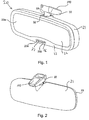
Figure 1 is a front perspective view of a rearview mirror assembly according to one embodiment of the invention. -
Figure 2 is a rear perspective view of the mirror assembly ofFigure 1 . -
Figure 3 is a rear view of the interior of the mirror ofFigure 1 . -
Figure 4 is a cross sectional view of the mirror ofFigure 3 taken along the line A-A. -
Figure 5 is a rear perspective view of the mirror ofFigure 1 with the housing removed. -
Figures 6 and 7 are cross sectional views of the mirror ofFigure 1 . -
Figure 7a is an exploded rear perspective view of the mirror ofFigure 1 . -
Figures 8 and 9 are rear perspective views of another embodiment of the invention, omitting the mirror housing. -
Figure 10 is a side view of the mirror unit and bracket ofFigures 8 and 9 . -
Figure 11 is a cross sectional view of the mirror unit and bracket ofFigures 8 and 9 taken on the line A-A ofFig. 10 . -
Figure 12 is a front perspective view of another embodiment of rearview mirror assembly according to the invention. -
Figure 13 is a exploded rear view of the rearview mirror assembly ofFigure 12 . -
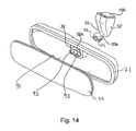
Figure 14 is a exploded front view of the rearview mirror assembly ofFigure 12 . -
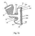
Figure 15 is a cross-sectional view of the mirror unit and support arm of the assembly ofFigure 12 taken on the line A-A ofFig. 16a . -
Figure 16 is a cross-sectional view of the mirror assembly ofFigure 12 taken on the line B-B ofFig. 16a . -
Figure 16a is a front view of the rearview mirror assembly ofFigure 12 . -
Figure 17 is a rear perspective view of part of another embodiment of the invention. -
Figure 18(a)-(d) are schematic diagrams illustrating large area sheets of glass from which individual front and rear glass plates used in electro-optical mirror units are cut. -
Figure 19 is a rear perspective view of a still further embodiment of the invention, omitting the housing and bezel. -
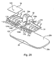
Figure 20 is an exploded view of the embodiment ofFigure 19 , omitting the bracket. -
Figure 21 shows the rear side (i.e. the side facing the backplate) of the PCB ofFigures 19 and20 , omitting all the circuitry except the light sensors and contact strips. -
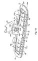
Figure 22 is a plan view of a phosphor bronze lead frame embedded in the backplate of the embodiment ofFigures 19 and20 . -
Figures 23(a) to 23(c) are various perspective views of the support bracket of the embodiment ofFigures 19 and20 . -
Figure 24(a) is a side view of the bracket ofFigure 23 . -
Figure 24(b) is a cross-section of the bracket ofFigure 23 taken on the line A-A ofFig. 24(a) . -
Figure 24(c) is a cross-section of the bracket ofFigure 23 taken on the line B-B ofFig. 24(b) . -
Figures 25(a) and 25(b) are perspective views of a further embodiment of bracket which could be used in the embodiment ofFigures 19 and20 . -
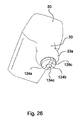
Figure 26 is a perspective views of a still further embodiment of bracket which could be used in the embodiment ofFigures 19 and20 . - As will be described in more detail, electro-optic mirror units comprise front and rear glass plates with an electro-optic medium sandwiched between them. The glass used in these units is highly specialised and expensive, and since the front and rear glass plates of an electro-optic mirror unit constitute a significant proportion of the costs of the overall mirror assembly it is very important to try to minimise wastage of glass from the plate glass from which the mirror glass profiles are cut. However, the problem is complicated by the fact that the transparent front TEC glass is provided in sheets of a different width from the sheets of the reflective rear ITO(Ag) glass, TEC and ITO(Ag) glasses being commercially available types of glass used in electro-optic mirror construction. Referring initially to
Figure 18, Fig. 18(a) shows the number (204) of front glass plates conventionally cut from a standard sheet of TEC glass measuring 3352.8mm x 1219.2mm, each glass plate being 249.5mm wide by 65.7mm high. By contrast,Fig. 18(b) shows the number (252) of front glass plates which may be produced from the same standard size sheet when each front glass plate is 219.4mm wide and 61.5mem high. This represents a 23% increase in the number of front glass plates available from the standard TEC glass sheet. Similarly,Fig. 18(c) shows that only 60 standard sized 249.5mm wide by 65.7mm high rear glass plates can be cut from a standard 1700mm by 750mm sheet of ITO(Ag) glass, whereasFig. 18(d) shows that 77 rear glass plates of size 219.4mm wide and 61.5mm high can be cut from the same ITO(Ag) glass sheet. This represents a 28% increase in the number of rear glass plates available from the standard ITO(Ag) glass sheet. - It has therefore been discovered that optimum usage of both the front and rear glass sheets is obtained by using front and rear mirror glass plates of size 219.4mm by 61.5mm. These are therefore the sizes of front and rear glass plates used in the various embodiments, except where otherwise noted. This minimises wastage and leads to optimum cost efficiency. In determining these sizes it has also been determined that in terms of a low cost electro-optic mirror the size of the mirror face is in fact larger than the average size of a prismatic type mirror face. Thus, the invention not only provides optimum efficiency in terms of glass usage and thus cost reduction by minimising wastage, but it also provides, a larger more effective mirror than the prismatic type mirror which it will replace.
- Referring now to
Figures 1 to 7 and7a , a rearview mirror assembly 20 comprises ahousing 21 containing an electro-optic mirror unit 22, abezel 23 which retains themirror unit 22 in the housing, themirror unit 22 being located just behind thebezel 23 and being viewable through the opening in the bezel, and asupport bracket 30 for attaching the assembly to the interior cabin of a vehicle, for example to the top of the windscreen or the header. In the present embodiment the upper end of thebracket 30 is adapted for sliding engagement with amirror mount 100, often referred to as a "button", which is adhesively attached to the interior surface of the windscreen in known manner. - Electro-optic mirror units are well-known in the art and typically comprise front and
rear glass plates Fig. 7 ) with a layer of an electro-optic medium (not shown) sandwiched between them. Thefront plate 22a is transparent and therear plate 22b has a layer of silver or other reflective material on its inside surface. Theunit 22 is positioned in thehousing 21 with thefront plate 22a exposed through the bezel opening so that the reflective layer on therear plate 22b is viewed through the front plate and the layer of electro-optic medium, The inside surface of each plate bears an electrically conductive electrode layer, the electrode layer on the front plate being transparent and the electrode layer on the rear plate also being transparent, at least if it is in front of the reflective layer (alternatively the reflective layer may also constitute the electrode layer for the rear plate so avoiding the need for a separate electrode layer on the rear plate). The light transmissivity of the electro-optic medium, and hence the reflectivity of the mirror unit, can be varied by the application of a variable control voltage across the electro-optic medium, i.e. across the conductive electrode layers on the inside surfaces of the plates. The electro-optic medium may comprise any material, for example electro-chromic or liquid crystal, which has the desired electro-optic properties. - The electro-
optic mirror unit 22 is preferably an electro-chromic (EC) cell either of the solid state type or electrochemichromic type, but may be any desired form of celL In the present embodiments themirror unit 22 is an BC cell whosefront plate 22a comprises TEC glass and whoserear plate 22b comprises ITO(Ag) glass. The electro-optic medium sandwiched between theplates US Patent 5 572 354 . However, this and following embodiments are not limited to the use of any particular types of glass, any particular type of electro-optic medium or any particular type of electro-optic mirror unit. - The front and
rear plates recess 25,Fig. 7a , provided in the bottom edge of therear plate 22b for a purpose to be described) but have a small vertical offset, so that the upper edge of therear plate 22b projects slightly above the upper edge of thefront plate 22a, and correspondingly the lower edge of thefront plate 22a projects slightly below the lower edge of therear plate 22b. This offset is clearly seen inFigs. 6 and 7 . The reason for the offset is to expose a narrow strip of the conductive electrode layer on the inside surface of therear plate 22b at the top of the mirror unit and a corresponding narrow strip of the conductive electrode layer on the inside surface of the front plate 2a at the bottom of the mirror unit. These exposed strips are electrically connected toconductive electrode contacts - The
EC cell 22 is securely fixed by adhesive, clips or other suitable means to anon-conductive backplate 31 moulded, for example, from glass-filled polypropylene (PP) or nylon. Asocket member 32 is mounted on the opposite side of thebackplate 31 to thecell 22, i.e. on the rear side of the backplate, and is preferably formed integrally with the backplate. Adependent portion 33 of thebracket 30 forms a corresponding ball member. The ball andsocket members Fig. 6 , such that a part-sphericalexternal surface 33a of theball member 33 is rotatable within a complementary part-sphericalinternal surface 32a of the socket member to allow a range of angular movement of the mirror unit relative to thebracket 30. Thebracket 30 is preferably moulded from a different material to thebackplate 31. For example, thebracket 30 can be moulded of nylon and the backplate, of PP, or vice versa. - A printed circuit board (PCB) 34 includes an electrical circuit for controlling the operation of the
EC cell 22, in particular by varying its reflectivity in response to the signals from a pair oflight sensors 26 and 27 (e.g. photodiodes or phototransistors) which are mounted on, but dependent via pairs ofrigid conductors PCB 34 is fixed by adhesive, clips or other suitable means to the rear side of thebackplate 31, the electrical circuit being on the side of the PCB facing the backplate and therefore not visible in the drawings. - The
backplate 31 haselectrical contacts electrode contacts Fig. 5 ) on thePCB 34 are connected to respective ones of thecontacts PCB 34 supplies the variable control voltage across theEC cell 22 via thepads 40. Awire harness 41 provides a power supply to thePCB 34 from the vehicle power supply. The arrangement of thecontact pads 40 andcontacts electrodes - The
backplate 31 has aboss 45 incorporating flaredapertures 46, 47 (Fig. 4 ) for accommodating thelight sensors sensors boss 45 provides very significant mechanical protection for the sensors and since thesurface 50 of thefront glass plate 22a is conductive an electrical path is available for discharge of electrostatic and other non-desirable electrical charges. Since thesensors rear glass plate 22b the bottom edge of the latter has arecess 25 relative to the front glass plate and theboss 45 is located in register with therecess 25. Thus thesensors transparent glass plate 22a unobstructed by therear glass plate 22b. Thesensors boss 45, i.e. normal to themirror unit 22 and generally facing the rear of the vehicle when the mirror assembly is mounted in the vehicle cabin for rearview viewing. - The
bezel 23 hasrespective apertures apertures boss 45. Thebezel aperture 23b is located directly in front of the flaredaperture 47 andsensor 27 so that the latter detects light directed along an axis generally normal to theEC cell 22. However, thebezel aperture 23a is laterally offset relative to thesensor 26 which, together with the skewed aspect of the flaredaperture 46 seen inFig. 4 , ensures that thesensor 26 detects light directed laterally from one side of the axis normal to the cell, i.e. from the direction V, despite facing in the same direction as thesensor 27. - In use, when the mirror assembly is mounted for rearward viewing in the interior cabin of a vehicle, the
sensor 27 senses light from the rear of the vehicle generally along a longitudinal axis of the vehicle while thesensor 26 senses light from the rear of the vehicle but obliquely to the right or to the left of the longitudinal vehicle axis. In particular, thesensor 26 senses light from a passenger or driver side window of the vehicle. Thus thesensor 27 acts as a glare sensor, since it is responsive to, for example, the glare from following headlamps, while thesensor 26 acts as an ambient sensor, since it is responsive to the general level of illumination outside the vehicle. - With both ambient and glare sensors facing rearwardly in the
bezel 23 thehousing 21 does not need to have an aperture for theambient sensor 26, which conventionally faces forwardly. - The
backplate 31 is also provided withresilient members 51 which abut and engageflanges 52 on the inside of thehousing 21 and provide rigidity and assist in vibration minimization. This construction eliminates further components while maintaining a support function. - The direct connection between the bracket 3 0 and the
backplate 31, which itself is directly fixed to theEC cell 22, improves the stiffness of the assembly that leads to an improvement in the vibration performance of the mirror and thus allows for the use of an all-plastic bracket support 30 which is a major reduction in the cost of the product. This also means that themirror housing 21 is not required as a structural component and principally serves as a cosmetic shroud around the mirror unit. This allows a low cost plastic such as PP to be used. As stated, thePCB 34 clips onto theback plate 31 and has theglare sensor 27 and theambient sensor 26 located together on thePCB 34. Thus theambient sensor 26 does not need to extend through the rear of themirror housing 21 and allows for thePCB 34 to be reduced in size and hence enables a cost reduction in the PCB. Since the backplate contains asupport boss 45 for the sensors, this eliminates the need for other sensor supports and hence a reduction in the component count is achieved, - One of the advantages of the above embodiment is that the glare and ambient light sensors are configured so as to view via apertures in the bezel portion of the mirror assembly. This is particularly useful when additional accessories (such as are disclosed in
US patents 6,124,8 86 ,6,245,262 and6,222,460 , are included in the cavity of the mirror housing. By configuring both sensors to view via bezel-located apertures/view-ports, additional accessories/structures can be accommodated within the mirror housing cavity without concern for occluding a field of view of either sensor. - Rather than having a
recess 25, therear glass plate 22b may have a portion of its reflective coating removed to enable positioning of the light sensors and the bezel in register with the area of reflective coating which is absent. Alternatively, the rear glass plate can have a transflective portion such as is disclosed inUS Patent 5,910,854 , the entire disclosure of which is hereby incorporated by reference herein. - Furthermore, microlouvers or angle-of-incidence-transmission-dependent films such as are available from 3M could enable the
sensor 26 to receive ambient light that is incident at an angle to the vehicle's longitudinal axis despite thesensor 26 facing in the same direction as theglare sensor 27. Alternatively, off-axis ambient light can be directed to thesensor 26 via a light pipe. - The above mirror assembly can be provided as an assembled kit but without the housing 21 (i.e. essentially as seen in
Fig. 5 ). Such kit would comprise an EC cell, a PCB (including EC cell drive circuitry), a backplate, first and second light sensors, a bracket, and a bezel with first and second apertures therein, with the second aperture that corresponds to the second or ambient light sensor being so located when the kit is married to a mirror housing during assembly of the complete interior mirror assembly, the second photo sensor views sideways from the mirror assembly when it is mounted in the vehicle cabin, i.e. towards a driver-side or passenger-side front side window. This facilitates assembly of such kits in a central manufacturing location, and then their shipment to remote mirror assembly plants located, for example, overseas, where the assembled kit is married with a locally-made mirror housing, any additional accessories and an (optionally) locally-made mirror mount to form a complete interior rearview mirror assembly. Alternatively, the kit need not be assembled prior to shipment, and the entire assembly from the component parts could take place at the final mirror assembly site. -
Figures 8 to 11 show another embodiment of the invention. In this embodiment similar numerals have been used for like parts as in the previous embodiment and only the differences between this embodiment and the embodiment ofFigure 1 will be described. InFigs. 8 to 11 thehousing 21 andbezel 23 are not shown. - In this embodiment only one
light sensor 60 is used which integrates both the glare and ambient functions and thissingle sensor 60 is located in aboss 61 on thebackplate 31 and will look through a single aperture (not shown) in thebezel 31. - In this embodiment
electrical contacts ball member 33 andelectrical contacts socket member 32. A portion of each of thecontacts external surface 33a of theball member 33 and a portion of each of thecontacts internal surface 32a of thesocket member 32. The orientation and positions of the portions of the electrical contacts 70-73 disposed on the part-spherical surfaces mirror unit 22 thecontact 70 is in sliding engagement with thecontact 72 and thecontact 71 is in sliding engagement with thecontact 73. - The
contacts ball member 33 to the upper end of thebracket 30 for making electrical contact with the vehicle electrical supply. Thecontacts PCB 34 atcontacts contacts contacts contacts PCB contacts PCB 34. This arrangement eliminates the need for a separate wire harness which reduces costs and enables the mirror to be assembled more easily. - In this embodiment the
backplate 31 incorporatesplastic tabs 96 which are coated with a conductive material, the conductive coating extending in astrip 98 along the bottom edge of thebackplate 31 and being electrically connected to thePCB 34 in the region of theboss 61. Theconductive tabs 96 resiliently press against the conductive surface of thefront glass plate 22a to provide an electrical connection from thePCB 34 to thefront glass plate 22a of theelectrochromic cell 22. This design eliminates oneelectrode strip 39 off theEC cell 22 and results in a saving of around 54% of the cost of theelectrode 39. -
Figures 12 to 16 and16a show a further embodiment of the invention. In this construction, thebackplate 31 of the previous embodiment is not used and thePCB 34 is fixed by adhesive, clips or other suitable means directly to therear plate 22b of theEC cell 22. Furthermore, only a singlelight sensor 80 is provided, in this embodiment near the top of the EC cell, asmall area 81 of the reflective layer on therear glass plate 22b being removed in register with thesensor 80 to allow the sensor to view through the transparentfront glass plate 22a. Alternatively, the top edge of therear glass plate 22b could be recessed, in a similar manner to that previously described for therecess 25 in the bottom edge, and thesensor 80 aligned with the recess. ThePCB 34 is electrically connected to the top edge of the conductive electrode layer on one of theglass plates EC cell 22 by anelectrical contact 90. - In the case where the edge of the
cell 22 has a conductive material it is sufficient for thecontact 90 to abut the edge of the cell. In the case where the edge of the cell does not have a conductive material it is necessary for thecontact 90 to be engaged or partly located between the front and rear glass sheets so as to make electrical connection with the relevant conductive electrode layer. Thecontact 90 is located in place during manufacture of the cell, and it is noted in this embodiment that thecontact 90 may be a conductive tape foil or layer. A similar arrangement (not shown) is used at the bottom of the cell to make electrical contact with the conductive electrode layer on the other of the glass plates of theEC cell 22. - In this embodiment, due to the absence of the
backplate 31, thesocket 32 is moulded into the rear of thehousing 21, but the same arrangement of slidably engagingelectrical contacts ball member 33 and thesocket member 31 respectively as previously described. At the inner surface of thesocket 32 resilientelectrical contacts 92, connected to thecontacts electrical contacts 93 on thePCB 34 to provide an electrical connection between thepower supply contacts PCB 34. - It will be noted from
Fig. 15 that in this embodiment the front andrear glass plates EC cell 22 are positioned in strict register with no vertical offset as is seen, for example, inFigures 6 and 7 . This means that the height of the mirror can be greater than that in the previous embodiments leading to an even better product. In the embodiment ofFigures 1 to 7 the height of the glass sheets is 61.5mm and the visible height of the mirror glass to the vehicle driver is 53mm. In the present embodiment the height of the glass is 59mm and because there is no offset in the front and rear glass plates the height of the visible mirror is again 53mm. Thus, less glass is used in this construction because of the lack of offset in the front and rear glass plates of theEC cell 22. In this case the number of TEC glass plates is increased by 25% and the number of ITO(Ag) glass plates is increased by 40% as compared with existing mirrors. Alternatively, if the height of the glass is maintained at 61.5mm, the visible height of the mirror would be 2.5mm greater at 55.5mm leading to an even better product. In this embodiment therefore, the cost can be reduced further or the size of the product can be increased because of the absence of overlapping glass sheets. Also the cost of providing theelectrodes - It will be seen from
Figs. 15 and16 that thehousing 21 has noseparate bezel 23, but rather thebezel 23 is integral with the main body of thehousing 21. Theintegral bezel 23 defines amirror viewing opening 23b which is slightly smaller than the lateral dimensions of theEC cell 22, as seen inFig. 15 . Therefore, in order to insert theEC cell 22 into thehousing 21 the latter is warmed sufficiently to the resiliently soften the housing polymeric material (e.g. PP or nylon) but not sufficiently for the housing to lose its structural integrity. Then theEC cell 22 is inserted behind thebezel 23 while thehousing 21 is still warm so that the edge of the EC cell is located in and gripped by ashallow recess 21 a of the housing just behind the bezel. Thereafter the housing is allowed to cool and become rigid. This method of assembly has the advantage that a separate bezel is not required and the number of parts is reduced. - However, due to the need to get the
EC cell 22 through the front opening in thehousing 21, the lateral dimensions of the opening are only slightly less than the lateral dimensions of the EC cell. This means that in the assembled mirror the bezel overlaps the edges of the EC cell by only a small amount, typically 1.5mm. This exposes the black epoxy lacquer seal which is conventionally coated around the edges of the glass plates and which extends partially onto the front surface of the front glass panel as a narrow strip several mm wide adjacent the edge. The exposed part of this seal, i.e. the part of the strip not covered by the bezel, will provide a cosmetic effect which can appear to the driver as part of the bezel itself. -
Figure 17 shows part of another embodiment of the invention in which theelectrical contact electrical contacts 40 on thePCB 34. This embodiment is a kind of hybrid of the embodiments ofFigs. 8-11 and12-16 , since it has asingle sensor 60 like the embodiment ofFigs. 8-11 but thePCB 34 is mounted directly on the rear of theEC cell 22 like the embodiment ofFigs. 12-16 . Alternatively there may be two light sensors as shown in relation toFigures 1-7 . It wall be appreciated that the embodiment ofFig. 17 will have ahousing 21 similar to that ofFigs. 12-16 , i.e. thesocket member 32 will be moulded to the rear of the housing. -
Figures 19 to 24 show another embodiment of the invention. In this embodiment similar numerals have been used for like parts as in the previous embodiment. InFigs. 19 to 24 thehousing 21 andbezel 23 are not shown, but may be fitted as described for the embodiment ofFigures 1 to 7 . - As in the first embodiment, in the present embodiment the
EC cell 22 is securely fixed by adhesive, clips or other suitable means to anon-conductive backplate 31 moulded, for example, from glass-filled polypropylene (PP) or nylon. Asocket member 32 is mounted on the opposite side of thebackplate 31 to thecell 22, i.e. on the rear side of the backplate, and is preferably formed integrally with the backplate. Thesocket member 32 engages with theball member 33 of asupport bracket 30 to allow angular adjustment of theEC cell 22. ThePCB 34 is fixed by adhesive, clips or other suitable means to the rear side of thebackplate 31, the electrical circuit being on the side of the PCB facing the backplate and therefore not being visible inFigs. 19 and20 . - An electrically conductive
lead frame 100,Fig. 22 , is embedded in thebackplate 31. Thelead frame 100 is stamped from a flat phosphor bronze sheet and is embedded into thebackplate 31 by moulding the latter around it, leaving certain contact and biasing fingers free of the moulded material as will be described. The lead frame comprises five electrically isolated portions A, B C, D and E (in actual fact, for ease of handling the four portions are initially joined by narrow bridges of phosphor bronze in the initial stamping but these are severed during or after the moulding process to isolate the four portions). The electrical functions of the five portions of the lead frame are:Portion A: Power supply +12v Portion B: Ground Portion C: EC cell anode (+ve) Portion D: EC cell cathode. Portion E: Heat Sink. - The EC cell cathode can be -ve or ground, and in the latter case the lead frame portions B and D can remain connected within the lead frame to provide one large ground plane providing substantial EMC protection.
- The lead frame fingers which are left free of and thus extend out of the moulded material of the
backplate 31 are as follows (see alsoFigs. 19-21 ): -
Spring contacts electrical contacts ball member 33. These connect respectively to power (+12v) and ground of the vehicle electrical supply via thebracket 30 as will be described. -
Spring contacts Fig. 21 ) on the side of thePCB 34 facing thebackplate 31. These transfer the power and ground of the vehicle electrical supply to thePCB 34 via the lead frame portions A and B. -
Spring contacts Fig. 21 ) on the side of thePCB 34 facing thebackplate 31. These receive the EC cell anode and cathode voltages from thePCB 34 for control of the EC cell reflectivity. - A
spring contact 108c which is bent upwardly out of the plane of the lead frame to make large area contact with thePCB 34 to dissipate heat from copper tracks and heat generating components on the "hottest" area of the PCB. The portion E thereby constitutes an efficient heat sink. - A plurality of contact fingers 112 (the outer pair of each group of three seen at the bottom of
Fig. 22 ) which are bent through 90 degrees at their outer ends to engage the conductive electrode layer on the inside surface of thefront glass plate 22a (the front andrear glass plates contact 108a via the lead frame portion C. - A pair of
contact fingers 114 which are bent through 90 degrees at their outer ends to engage the conductive electrode layer on the inside surface of therear glass plate 22b. These apply the EC cell cathode voltage from thecontact 108b via the lead frame portion D. - A plurality of
spring fingers 116 which are bent out of the plane of the lead frame from the portions B, C and D to bear resiliently against the interior of the mirror housing 21 (not shown) to stabilise theEC cell 22 within the housing (at the bottom of the lead frame thespring fingers 116 are the centre fingers of each group of three). - This embodiment again uses ambient and
glare light sensors PCB 34 rather than depending from it. As before, theglare sensor 27 faces rearwardly of the vehicle when the mirror is mounted in the vehicle cabin and views through the transparentfront glass plate 22a of the EC cell via arecess 25 in the edge of therear glass plate 22b. However, theambient sensor 26 in this case faces forwardly (relative to the vehicle) and views forwardly of the vehicle through anaperture 120 in thePCB 34 and a corresponding aperture (not shown) in the mirror housing. When thePCB 34 is mounted on thebackplate 31 thesensors housing 122 moulded to thebackplate 31, the housing both mechanically protecting the sensors and shielding them from extraneous light. Alternatively, a single light sensor may be positioned so that it is shrouded from stray light by a feature of the backplate, receives glare light though an aperture in the bezel and through the recess in the rear glass and receives ambient light from the opposite direction through a hole in the PCB and an aperture in the mirror housing. This one sensor can monitor both ambient and glare light levels. Where two sensors are used, mounting them close together on thePCB 34 reduces adverse EMC effects by eliminating long conductive lines between the sensors. - The
bracket 30,Figs. 23 and24 , is (except as noted below) moulded from glass-filled polypropylene (PP) or nylon. It has an upper end withinternal rails 124 for sliding engagement with a "button"-type mirror mount 100 for attachment of the bracket to the interior surface of a vehicle windscreen in conventional manner. Thebracket 30 further includes aball member 33 which depends from the upper end of the bracket and has a part-sphericalexternal surface 33a rotatable within a complementary part-sphericalinternal surface 32a (Fig. 20 ) of thesocket member 32 to allow a range of angular movement of theEC mirror unit 22 relative to the bracket 3 0. - The
ball member 33 comprises a centralcylindrical bore 126 and acylindrical body 128 of electrically insulating material extending fully through thebore 126 from the upper end of the bracket and terminating in an exposedconvex surface 130 below the lower end of the bore. Thebody 128 comprises three parts: two outer generallysemi-cylindrical parts planar part 128c. At the upper end of the bracket theparts integral spring arms 132, and at the lower and of thebody 128 all three parts collectively define theconvex surface 130. - The outer surfaces of the
semi-cylindrical parts convex surface 130 to form respectiveelectrical contacts part respective spring arm 132. Thus a direct electrical path is made from eachelectrical contact convex surface 130 to a respective one of thespring arms 132. Thecentral part 128c, which is not conductively coated, prevents any short circuit between the two paths. - When the upper end of the
bracket 30 is mounted to amounting button 100 thespring arms 132 engage conductive tracks (not shown) on the inside surface of the windscreen, such tracks providing vehicle power and ground which are thereby transferred to therespective contacts body 128. Thecontacts frame spring contacts EC cell 22 for supplying power to thePCB 34 from the vehicle electrical system. - The
body 128 may be manufactured in threepieces bore 126 as indicated for thepart 128b inFig. 23 (a) . In such a case theouter parts part 128b) and individually moulded of polysulphide or other electroplatable material and subsequently plated with conductive coatings. Thecentre part 128c can be moulded of the same material but left unplated, or it can be moulded, like the rest of the bracket 10, of a polymeric material such as PP or nylon. However, a two-shot moulding process may be used. In the first shot, thecentral part 128c is moulded using a material which cannot be electroplated. Then, in the second shot, the outersemi-cylindrical parts centre part 128c but using a material such as polysulphide which can be plated. Then theentire body 128 is subject to electroplating, but the plating only "takes" to theouter parts - In an alternative embodiment of the
bracket 30,Fig. 25 , thespring contacts 132 are replaced by aplug 136 of a standard plug and socket connector and the conductive coatings on thebody 128 extend onto theplug 136. - In a modification of the above embodiment, the
body 128 could comprise more than two independently platedparts - Alternatively,
Fig. 26 , the data connection could be provided by asolid conductor 134c embedded in and extending the full length of thecentral part 128c. The surface of theconductor 134c exposed at the lower end of thepart 128c could be slidingly engaged by a further spring contact extending from the lead frame, similar to thecontacts ball member 33 andsocket member 32 respectively are designed to limit the degree of angular adjustment of the mirror to ensure that each spring contact remains in engagement with its respective contact on the lower end of thebody 128.
Claims (17)
- A rearview mirror assembly (20) for a vehicle comprising:an electro-optic mirror unit (22) whose reflectivity is variable in response to an electrical voltage applied thereto;at least one light sensor (27);an electrical circuit (34) for controlling operation of the mirror unit in response to the at least one light sensor; anda bracket (30) for supporting the mirror unit from an interior portion of the vehicle via interengaging ball (33) and socket members (32) to allow angular adjustment of the mirror unit, one of the ball and socket members being fixed to the bracket and the other of the ball and socket members being fixed relative to the mirror unit;characterised in that the ball member (33) includes a plurality of electrical contacts (70, 71) for sliding engagement by respective counter-contacts (72, 73) over a range of angular movement of the mirror unit for supplying power to the electrical circuit from a vehicle electrical system external to the mirror assembly.
- The assembly of claim 1, wherein the ball member (33) is fixed to the bracket (30) and the socket member (32) is fixed relative to the mirror unit.
- The assembly of claim 2, wherein the mirror unit (22) is mounted on one side of a backplate (31) and the socket member (32) is disposed on the opposite side of the backplate to the mirror unit.
- The assembly of claim 2, further including a mirror housing (21) containing the said mirror unit (22), wherein the socket member is disposed on the mirror housing.
- The assembly of claim 2, wherein a convex surface (33a) of the ball member is exposed by the socket member (32) and the electrical contacts (70, 71) are disposed on respective areas of the exposed convex surface.
- The assembly of claim 5, wherein the counter-contacts (72, 73) comprise spring fingers (102a, 102b) biased into engagement with the respective areas of the exposed convex surface (134a, 134b).
- The assembly of claim 3, wherein a convex surface of the ball member (33) is exposed by the socket member and the electrical contacts (134a, 134b) are disposed on respective areas of the exposed convex surface, wherein the backplate (31) is of electrically non-conductive material and has a conductive lead frame (100) embedded therein, and wherein the counter-contacts comprise spring contacts (102a, 102b) biased into engagement with the respective areas (134a, 134b) of the exposed convex surface, the spring contacts extending from the lead frame out of the backplate.
- The assembly of claim 7, wherein the electrical circuit is (34) mounted on the said opposite side of the backplate (31) and is electrically connected to the counter-contacts by further spring contacts extending from the lead frame (100) out of the backplate.
- The assembly of claim 3, wherein a conductive lead frame (100) is embedded in the backplate (31), the backplate being of non electrically conductive material, and wherein the electrical circuit is mounted on the said opposite side of the backplate and is electrically connected to the lead frame (100) by spring contacts (104a, 104b) extending from the lead frame out of the backplate.
- The assembly of claim 9, wherein the lead frame (100) includes a plurality of further contacts (112) extending from opposite edges of the backplate and making electrical contact with opposite edges of the mirror unit for allowing the electrical circuit to control the operation of the mirror unit.
- The assembly of claim 5, wherein the ball member (33) depends from an upper end of the bracket which is adapted to be attached to a mirror mount fixed to an interior surface of the vehicle, the electrical contacts extending upwardly of the ball member from the said exposed convex surface to the upper end of the bracket for connection to the vehicle electrical system.
- The assembly of claim 11, wherein the ball member (33) comprises a central bore (126) and an electrically insulating body extending folly through the bore from the upper end of the bracket, the lower end of the said body constituting the said exposed convex surface (130), and wherein the electrical contacts are formed as conductive coatings on the said areas of the exposed convex surface, the coatings extending along the length of the outer surface of the body to the upper end of the bracket for connection to the vehicle electrical system.
- The assembly of claim 12, wherein the upper end of the body has integral spring members (132) for engaging conductive tracks on the interior of the vehicle windscreen, the conductive coatings extending onto respective spring members.
- The assembly of claim 12, wherein the upper end of the body has one part of a plug and socket connector (136) and the conductive coatings (128) extend onto the connector.
- The assembly of claim 1, wherein a part-spherical external surface of the ball member (33a) is rotatable within a complementary part-spherical internal surface of the socket member (32a), and wherein the electrical contacts (70, 71) are disposed on the part-spherical external surface of the ball member and the counter-contacts (72, 73) are disposed on the part-spherical internal surface of the socket member.
- The assembly of claim 15, wherein the mirror unit is mounted on one side of a backplate, and the socket member is mounted on the opposite side of the backplate to the mirror unit.
- The assembly of claim 15, further including a mirror housing containing the said mirror unit, wherein the socket member is mounted on the mirror housing.
Applications Claiming Priority (5)
| Application Number | Priority Date | Filing Date | Title |
|---|---|---|---|
| IE20020314 | 2002-04-26 | ||
| IE20020314 | 2002-04-26 | ||
| IE20020545 | 2002-07-01 | ||
| IE20020545 | 2002-07-01 | ||
| PCT/IE2003/000059 WO2003095269A2 (en) | 2002-04-26 | 2003-04-25 | Rearview mirror assemblies |
Publications (2)
| Publication Number | Publication Date |
|---|---|
| EP1523432A2 EP1523432A2 (en) | 2005-04-20 |
| EP1523432B1 true EP1523432B1 (en) | 2010-09-08 |
Family
ID=29422207
Family Applications (1)
| Application Number | Title | Priority Date | Filing Date |
|---|---|---|---|
| EP03749972A Expired - Lifetime EP1523432B1 (en) | 2002-04-26 | 2003-04-25 | Rearview mirror assemblies |
Country Status (5)
| Country | Link |
|---|---|
| US (4) | US7110156B2 (en) |
| EP (1) | EP1523432B1 (en) |
| AU (1) | AU2003225513A1 (en) |
| DE (1) | DE60334100D1 (en) |
| WO (1) | WO2003095269A2 (en) |
Families Citing this family (57)
| Publication number | Priority date | Publication date | Assignee | Title |
|---|---|---|---|---|
| US6822563B2 (en) | 1997-09-22 | 2004-11-23 | Donnelly Corporation | Vehicle imaging system with accessory control |
| US5877897A (en) | 1993-02-26 | 1999-03-02 | Donnelly Corporation | Automatic rearview mirror, vehicle lighting control and vehicle interior monitoring system using a photosensor array |
| US6891563B2 (en) | 1996-05-22 | 2005-05-10 | Donnelly Corporation | Vehicular vision system |
| US7655894B2 (en) | 1996-03-25 | 2010-02-02 | Donnelly Corporation | Vehicular image sensing system |
| US6553308B1 (en) | 1999-04-29 | 2003-04-22 | Donnelly Corporation | Vehicle-based navigation system with smart map filtering, portable unit home-base registration and multiple navigation system preferential use |
| US7110156B2 (en) * | 2002-04-26 | 2006-09-19 | Donnelly Mirrors Limited | Rearview mirror assemblies |
| AU2003225228A1 (en) | 2002-05-03 | 2003-11-17 | Donnelly Corporation | Object detection system for vehicle |
| US20060061008A1 (en) | 2004-09-14 | 2006-03-23 | Lee Karner | Mounting assembly for vehicle interior mirror |
| US10144353B2 (en) | 2002-08-21 | 2018-12-04 | Magna Electronics Inc. | Multi-camera vision system for a vehicle |
| DE10300232A1 (en) * | 2003-01-02 | 2004-07-15 | Schefenacker Vision Systems Germany Gmbh & Co. Kg | Interior rear view mirror for vehicles, preferably for motor vehicles |
| US7526103B2 (en) | 2004-04-15 | 2009-04-28 | Donnelly Corporation | Imaging system for vehicle |
| WO2006014209A2 (en) * | 2004-06-08 | 2006-02-09 | Gentex Corporation | Rearview assembly having an integral crush zone |
| US7706046B2 (en) | 2004-06-08 | 2010-04-27 | Gentex Corporation | Rearview mirror element having a circuit mounted to the rear surface of the element |
| US7881496B2 (en) | 2004-09-30 | 2011-02-01 | Donnelly Corporation | Vision system for vehicle |
| US7510287B2 (en) * | 2005-10-21 | 2009-03-31 | Donnelly Corporation | Wire cover assembly for vehicle interior mirror |
| CN101421132B (en) * | 2005-11-18 | 2011-09-21 | 麦格纳唐纳利工程有限公司 | EC mirror assembly |
| US7972045B2 (en) | 2006-08-11 | 2011-07-05 | Donnelly Corporation | Automatic headlamp control system |
| US8503061B2 (en) | 2009-03-30 | 2013-08-06 | Magna Mirrors Of America, Inc. | Electro-optic rearview mirror assembly for vehicle |
| US11325533B2 (en) | 2009-04-23 | 2022-05-10 | Magna Mirrors Of America, Inc. | Frameless interior rearview mirror assembly |
| WO2010124064A1 (en) | 2009-04-23 | 2010-10-28 | Magna Mirrors Of America, Inc. | Mirror assembly for vehicle |
| US10261648B2 (en) | 2009-10-07 | 2019-04-16 | Magna Mirrors Of America, Inc. | Exterior rearview mirror assembly |
| US9346403B2 (en) | 2009-10-07 | 2016-05-24 | Magna Mirrors Of America, Inc. | Rearview mirror assembly |
| US11498486B2 (en) | 2009-10-07 | 2022-11-15 | Magna Mirrors Of America, Inc. | Vehicular exterior rearview mirror assembly |
| US9598016B2 (en) | 2010-10-15 | 2017-03-21 | Magna Mirrors Of America, Inc. | Interior rearview mirror assembly |
| EP2485921B1 (en) | 2009-10-07 | 2016-06-15 | Magna Mirrors Of America, Inc. | Frameless interior rearview mirror assembly |
| US8851690B2 (en) | 2009-10-27 | 2014-10-07 | Magna Mirrors Of America, Inc. | Mounting assembly for vehicle interior mirror |
| US9205780B2 (en) | 2010-02-04 | 2015-12-08 | Magna Mirrors Of America, Inc. | Electro-optic rearview mirror assembly for vehicle |
| US9969334B2 (en) | 2010-02-10 | 2018-05-15 | Magna Mirrors Of America, Inc. | Exterior rearview mirror assembly |
| US9827913B2 (en) | 2010-02-10 | 2017-11-28 | Magna Mirrors Of America, Inc. | Exterior rearview mirror assembly |
| US12115913B2 (en) | 2010-02-10 | 2024-10-15 | Magna Mirrors Of America, Inc. | Vehicular exterior rearview mirror system |
| USD638761S1 (en) | 2010-09-29 | 2011-05-31 | Magna Mirrors Of America, Inc. | Vehicular electro-optic mirror assembly |
| USD647017S1 (en) | 2010-09-29 | 2011-10-18 | Magna Mirrors Of America, Inc. | Vehicular prismatic mirror assembly |
| US8827517B2 (en) * | 2010-10-12 | 2014-09-09 | Gentex Corporation | Clear bezel |
| US20120235436A1 (en) * | 2011-03-17 | 2012-09-20 | Ford Global Technologies, Llc | One-piece decorative trim bezel having plural unpainted finishes |
| US8988755B2 (en) | 2011-05-13 | 2015-03-24 | Magna Mirrors Of America, Inc. | Mirror reflective element |
| PT2572933E (en) * | 2011-09-21 | 2013-11-11 | Semitron S A Electronic Electrical Construction Sa | Mirror-type taximeter support system |
| USD661234S1 (en) | 2011-10-14 | 2012-06-05 | Magna Mirrors Of America, Inc. | Vehicular electro-optic mirror assembly |
| USD660208S1 (en) | 2011-10-14 | 2012-05-22 | Magna Mirrors Of America, Inc. | Vehicular prismatic mirror assembly |
| US10457209B2 (en) | 2012-02-22 | 2019-10-29 | Magna Electronics Inc. | Vehicle vision system with multi-paned view |
| US9244249B2 (en) | 2012-09-28 | 2016-01-26 | Gentex Corporation | Double ball slide on mount with screw over sensor |
| US9352691B2 (en) | 2012-11-05 | 2016-05-31 | Magna Mirrors Of America, Inc. | Interior rearview mirror assembly |
| DE102013203531B3 (en) * | 2013-03-01 | 2014-05-22 | Magna Mirrors Holding Gmbh | Rearview mirror assembly for motor vehicles |
| US9174578B2 (en) | 2013-04-22 | 2015-11-03 | Magna Mirrors Of America, Inc. | Interior rearview mirror assembly |
| US9676336B2 (en) | 2013-06-25 | 2017-06-13 | Magna Mirrors Of America, Inc. | Exterior rearview mirror assembly for vehicle |
| US9487142B2 (en) | 2013-06-25 | 2016-11-08 | Magna Mirrors Of America, Inc. | Rearview mirror assembly for vehicle |
| US9454054B2 (en) | 2013-11-18 | 2016-09-27 | Magna Mirrors Of America, Inc. | Electro-optic mirror element and process of making same |
| US10429713B2 (en) | 2014-06-12 | 2019-10-01 | Gentex Corporation | Selectively-transparent electrochromic display |
| US9796334B2 (en) | 2014-06-13 | 2017-10-24 | Magna Mirrors Of America, Inc. | Exterior rearview mirror assembly for vehicle |
| USD750979S1 (en) * | 2014-10-13 | 2016-03-08 | Gentex Corporation | Light sensor |
| US10554700B2 (en) * | 2015-08-04 | 2020-02-04 | At&T Intellectual Property I, L.P. | Method and apparatus for management of communication conferencing |
| JP7122561B2 (en) * | 2018-12-13 | 2022-08-22 | パナソニックIpマネジメント株式会社 | In-vehicle accessory device, in-vehicle display system |
| US11938795B2 (en) | 2019-10-18 | 2024-03-26 | Magna Electronics Inc. | Vehicular vision system with glare reducing windshield |
| US12246648B2 (en) | 2021-01-19 | 2025-03-11 | Magna Mirrors Of America, Inc. | Vehicular exterior rearview mirror assembly with locking feature |
| DE102021108507B3 (en) * | 2021-04-06 | 2022-07-07 | Mekra Lang Gmbh & Co. Kg | Indirect rearview system with contact areas of a support element on both sides of a parting surface, load-optimized adjustment ball and assembly method for an indirect rearview system |
| US12351108B2 (en) | 2021-07-09 | 2025-07-08 | Magna Mirrors Of America, Inc. | Vehicular exterior rearview mirror assembly with extendable and retractable mirror head |
| US20230111985A1 (en) * | 2021-10-12 | 2023-04-13 | Magna Mirrors Of America, Inc. | Low profile auto-dimming interior rearview mirror assembly |
| CN119329410B (en) * | 2024-11-26 | 2025-09-19 | 岚图汽车科技有限公司 | Rearview mirror device and automobile |
Family Cites Families (33)
| Publication number | Priority date | Publication date | Assignee | Title |
|---|---|---|---|---|
| US4012022A (en) | 1974-08-12 | 1977-03-15 | Ichikoh Industries Limited | Breakaway mirror mounting |
| FR2504075A1 (en) * | 1981-04-15 | 1982-10-22 | Hohe Kg | VEHICLE OUTSIDE MIRROR |
| US4524941A (en) | 1981-06-24 | 1985-06-25 | Donnelly Corporation | Rearview mirror support bracket |
| US4623222A (en) * | 1983-11-14 | 1986-11-18 | Nippondenso Co., Ltd. | Liquid crystal type dazzle-free transmissive-reflective mirror |
| JPS60143301A (en) * | 1983-12-29 | 1985-07-29 | Nippon Denso Co Ltd | Nonglaring type reflection mirror and its manufacture |
| DE3636495A1 (en) * | 1986-10-27 | 1988-04-28 | Bernhard Mittelhaeuser | REAR VIEW MIRROR FOR MOTOR VEHICLES |
| DE8701766U1 (en) * | 1987-02-06 | 1987-07-16 | Hohe Kg, 6981 Collenberg | Exterior mirror for a vehicle with mechanically adjustable mirror |
| DE3811448A1 (en) * | 1987-09-09 | 1989-03-23 | Mekra Rangau Plastics | MOTOR ADJUSTABLE REAR MIRROR |
| US4936533A (en) | 1988-11-15 | 1990-06-26 | Donnelly Corporation | Mounting assembly for vehicle accessories |
| US5151816A (en) | 1989-12-29 | 1992-09-29 | Donnelly Corporation | Method for reducing current leakage and enhancing uv stability in electrochemichromic solutions and devices |
| US5058851A (en) | 1989-04-14 | 1991-10-22 | Donnelly Mirrors Limited | Mounting assembly for rearview mirror |
| US5140455A (en) | 1989-11-29 | 1992-08-18 | Donnelly Corporation | High performance electrochemichromic solutions and devices thereof |
| US5910854A (en) | 1993-02-26 | 1999-06-08 | Donnelly Corporation | Electrochromic polymeric solid films, manufacturing electrochromic devices using such solid films, and processes for making such solid films and devices |
| US5877897A (en) | 1993-02-26 | 1999-03-02 | Donnelly Corporation | Automatic rearview mirror, vehicle lighting control and vehicle interior monitoring system using a photosensor array |
| EP0615882A3 (en) * | 1993-03-19 | 1994-11-02 | Donnelly Mirrors Ltd | Rearview mirror assembly. |
| US5659423A (en) | 1994-09-30 | 1997-08-19 | Donnelly Corporation | Modular variable reflectance mirror assembly |
| US5671996A (en) * | 1994-12-30 | 1997-09-30 | Donnelly Corporation | Vehicle instrumentation/console lighting |
| US5669698A (en) * | 1995-05-24 | 1997-09-23 | Veldman; Roger L. | Modular rearview mirror assembly and method for making same |
| EP0897347B1 (en) * | 1996-03-19 | 2002-01-23 | Donnelly Mirrors Limited | Electro-optic rearview mirror system |
| US6124886A (en) * | 1997-08-25 | 2000-09-26 | Donnelly Corporation | Modular rearview mirror assembly |
| US6326613B1 (en) * | 1998-01-07 | 2001-12-04 | Donnelly Corporation | Vehicle interior mirror assembly adapted for containing a rain sensor |
| US6172613B1 (en) * | 1998-02-18 | 2001-01-09 | Donnelly Corporation | Rearview mirror assembly incorporating vehicle information display |
| US6087953A (en) | 1998-02-18 | 2000-07-11 | Donnelly Corporation | Rearview mirror support incorporating vehicle information display |
| US6428172B1 (en) * | 1999-11-24 | 2002-08-06 | Donnelly Corporation | Rearview mirror assembly with utility functions |
| US6329925B1 (en) * | 1999-11-24 | 2001-12-11 | Donnelly Corporation | Rearview mirror assembly with added feature modular display |
| GB2342467B (en) * | 1998-10-09 | 2003-06-04 | Donnelly Corp | A light-reponsive vehicle control such as an electro-optic rearview mirror system that is adaptive to vehicle configuration |
| US5971553A (en) * | 1999-02-16 | 1999-10-26 | Gentex Corporation | Mirror housing with electrical connector |
| US6023229A (en) * | 1999-03-02 | 2000-02-08 | Gentex Corp | Rearview mirror with internally-mounted compass sensor |
| EP1103420B1 (en) * | 1999-11-24 | 2006-06-21 | Donnelly Corporation | Rearview mirror assembly with utility functions |
| US6520667B1 (en) * | 2000-09-15 | 2003-02-18 | Donnelly Corporation | Vehicle interior rearview mirror assembly with display |
| US7255451B2 (en) * | 2002-09-20 | 2007-08-14 | Donnelly Corporation | Electro-optic mirror cell |
| US7543946B2 (en) * | 2002-01-10 | 2009-06-09 | Gentex Corporation | Dimmable rearview assembly having a glare sensor |
| US7110156B2 (en) | 2002-04-26 | 2006-09-19 | Donnelly Mirrors Limited | Rearview mirror assemblies |
-
2003
- 2003-04-25 US US10/512,206 patent/US7110156B2/en not_active Expired - Fee Related
- 2003-04-25 AU AU2003225513A patent/AU2003225513A1/en not_active Abandoned
- 2003-04-25 WO PCT/IE2003/000059 patent/WO2003095269A2/en not_active Ceased
- 2003-04-25 EP EP03749972A patent/EP1523432B1/en not_active Expired - Lifetime
- 2003-04-25 DE DE60334100T patent/DE60334100D1/en not_active Expired - Lifetime
-
2006
- 2006-08-03 US US11/498,420 patent/US7209278B2/en not_active Expired - Fee Related
-
2007
- 2007-04-23 US US11/738,649 patent/US7310178B2/en not_active Expired - Fee Related
- 2007-12-17 US US11/957,939 patent/US7599108B2/en not_active Expired - Fee Related
Also Published As
| Publication number | Publication date |
|---|---|
| US20050174622A1 (en) | 2005-08-11 |
| WO2003095269A3 (en) | 2004-03-18 |
| US7599108B2 (en) | 2009-10-06 |
| US20070008604A1 (en) | 2007-01-11 |
| US7209278B2 (en) | 2007-04-24 |
| EP1523432A2 (en) | 2005-04-20 |
| AU2003225513A1 (en) | 2003-11-11 |
| US7310178B2 (en) | 2007-12-18 |
| WO2003095269A2 (en) | 2003-11-20 |
| US20070188844A1 (en) | 2007-08-16 |
| DE60334100D1 (en) | 2010-10-21 |
| US20080180780A1 (en) | 2008-07-31 |
| AU2003225513A8 (en) | 2003-11-11 |
| US7110156B2 (en) | 2006-09-19 |
Similar Documents
| Publication | Publication Date | Title |
|---|---|---|
| US7310178B2 (en) | Rearview mirror assembly for a vehicle | |
| US11230227B2 (en) | Mirror assembly with spring-loaded electrical connectors | |
| US11623570B2 (en) | Vehicular exterior rearview mirror assembly with blind spot indicator module | |
| US11358528B2 (en) | Vehicular rearview mirror assembly with spring-loaded electrical connector | |
| US11285888B2 (en) | Electrochromic mirror reflective element for vehicular rearview mirror assembly | |
| WO2000070374A1 (en) | Exterior mirror sub-assembly with combined electronic circuitry and mirror element | |
| US7858905B2 (en) | Vehicular mirror with heater circuit module | |
| US11858422B2 (en) | Vehicular rearview mirror assembly | |
| US20130153127A1 (en) | Method of manufacturing a reflective element for a vehicular rearview mirror assembly | |
| GB2296479A (en) | Waterproofing for the electrochromic device of a rearview mirror | |
| ES2550534T3 (en) | Electro-optic reflector element set | |
| US20230111985A1 (en) | Low profile auto-dimming interior rearview mirror assembly | |
| US20230278498A1 (en) | Vehicular exterior rearview mirror assembly with blind spot indicator element | |
| US11414014B2 (en) | Interior rearview mirror assembly with circuitry at mirror mount | |
| US20250074309A1 (en) | Vehicular interior rearview mirror assembly with electrification of electrochromic mirror | |
| US20240351522A1 (en) | Electro-optic mirror reflective element sub-assembly for vehicular rearview mirror assembly |
Legal Events
| Date | Code | Title | Description |
|---|---|---|---|
| PUAI | Public reference made under article 153(3) epc to a published international application that has entered the european phase |
Free format text: ORIGINAL CODE: 0009012 |
|
| 17P | Request for examination filed |
Effective date: 20041126 |
|
| AK | Designated contracting states |
Kind code of ref document: A2 Designated state(s): AT BE BG CH CY CZ DE DK EE ES FI FR GB GR HU IE IT LI LU MC NL PT RO SE SI SK TR |
|
| AX | Request for extension of the european patent |
Extension state: AL LT LV MK |
|
| 17Q | First examination report despatched |
Effective date: 20081001 |
|
| RAP1 | Party data changed (applicant data changed or rights of an application transferred) |
Owner name: MAGNA DONNELLY ENGINEERING GMBH |
|
| GRAP | Despatch of communication of intention to grant a patent |
Free format text: ORIGINAL CODE: EPIDOSNIGR1 |
|
| GRAC | Information related to communication of intention to grant a patent modified |
Free format text: ORIGINAL CODE: EPIDOSCIGR1 |
|
| GRAS | Grant fee paid |
Free format text: ORIGINAL CODE: EPIDOSNIGR3 |
|
| GRAA | (expected) grant |
Free format text: ORIGINAL CODE: 0009210 |
|
| AK | Designated contracting states |
Kind code of ref document: B1 Designated state(s): DE FR GB |
|
| REG | Reference to a national code |
Ref country code: GB Ref legal event code: FG4D |
|
| REF | Corresponds to: |
Ref document number: 60334100 Country of ref document: DE Date of ref document: 20101021 Kind code of ref document: P |
|
| PLBE | No opposition filed within time limit |
Free format text: ORIGINAL CODE: 0009261 |
|
| STAA | Information on the status of an ep patent application or granted ep patent |
Free format text: STATUS: NO OPPOSITION FILED WITHIN TIME LIMIT |
|
| 26N | No opposition filed |
Effective date: 20110609 |
|
| REG | Reference to a national code |
Ref country code: DE Ref legal event code: R097 Ref document number: 60334100 Country of ref document: DE Effective date: 20110609 |
|
| REG | Reference to a national code |
Ref country code: FR Ref legal event code: PLFP Year of fee payment: 14 |
|
| REG | Reference to a national code |
Ref country code: FR Ref legal event code: PLFP Year of fee payment: 15 |
|
| REG | Reference to a national code |
Ref country code: FR Ref legal event code: PLFP Year of fee payment: 16 |
|
| PGFP | Annual fee paid to national office [announced via postgrant information from national office to epo] |
Ref country code: DE Payment date: 20180420 Year of fee payment: 16 |
|
| PGFP | Annual fee paid to national office [announced via postgrant information from national office to epo] |
Ref country code: FR Payment date: 20180420 Year of fee payment: 16 |
|
| PGFP | Annual fee paid to national office [announced via postgrant information from national office to epo] |
Ref country code: GB Payment date: 20180418 Year of fee payment: 16 |
|
| REG | Reference to a national code |
Ref country code: DE Ref legal event code: R119 Ref document number: 60334100 Country of ref document: DE |
|
| GBPC | Gb: european patent ceased through non-payment of renewal fee |
Effective date: 20190425 |
|
| PG25 | Lapsed in a contracting state [announced via postgrant information from national office to epo] |
Ref country code: GB Free format text: LAPSE BECAUSE OF NON-PAYMENT OF DUE FEES Effective date: 20190425 Ref country code: DE Free format text: LAPSE BECAUSE OF NON-PAYMENT OF DUE FEES Effective date: 20191101 |
|
| PG25 | Lapsed in a contracting state [announced via postgrant information from national office to epo] |
Ref country code: FR Free format text: LAPSE BECAUSE OF NON-PAYMENT OF DUE FEES Effective date: 20190430 |
|
| P01 | Opt-out of the competence of the unified patent court (upc) registered |
Effective date: 20230509 |