EP1523263B1 - Machine for the production of hot water, steam and hot drinks - Google Patents
Machine for the production of hot water, steam and hot drinks Download PDFInfo
- Publication number
- EP1523263B1 EP1523263B1 EP02765327A EP02765327A EP1523263B1 EP 1523263 B1 EP1523263 B1 EP 1523263B1 EP 02765327 A EP02765327 A EP 02765327A EP 02765327 A EP02765327 A EP 02765327A EP 1523263 B1 EP1523263 B1 EP 1523263B1
- Authority
- EP
- European Patent Office
- Prior art keywords
- boiler
- water
- temperature
- steam
- transducer
- Prior art date
- Legal status (The legal status is an assumption and is not a legal conclusion. Google has not performed a legal analysis and makes no representation as to the accuracy of the status listed.)
- Expired - Lifetime
Links
- XLYOFNOQVPJJNP-UHFFFAOYSA-N water Substances O XLYOFNOQVPJJNP-UHFFFAOYSA-N 0.000 title claims abstract description 99
- 235000012171 hot beverage Nutrition 0.000 title claims abstract description 11
- 238000004519 manufacturing process Methods 0.000 title description 3
- 238000010438 heat treatment Methods 0.000 claims abstract description 78
- 230000004913 activation Effects 0.000 claims abstract description 17
- 230000004044 response Effects 0.000 claims abstract description 14
- 229920006395 saturated elastomer Polymers 0.000 claims abstract description 6
- 238000009825 accumulation Methods 0.000 claims abstract description 5
- 238000012544 monitoring process Methods 0.000 claims 2
- 230000006833 reintegration Effects 0.000 abstract description 9
- 235000013353 coffee beverage Nutrition 0.000 description 28
- 235000016213 coffee Nutrition 0.000 description 27
- 238000010586 diagram Methods 0.000 description 19
- 230000000875 corresponding effect Effects 0.000 description 12
- 238000000034 method Methods 0.000 description 12
- 230000008569 process Effects 0.000 description 12
- 230000000694 effects Effects 0.000 description 11
- 239000008267 milk Substances 0.000 description 9
- 210000004080 milk Anatomy 0.000 description 9
- 235000013336 milk Nutrition 0.000 description 9
- 230000001934 delay Effects 0.000 description 8
- 239000007788 liquid Substances 0.000 description 5
- 235000013616 tea Nutrition 0.000 description 5
- 241001122767 Theaceae Species 0.000 description 4
- 235000015116 cappuccino Nutrition 0.000 description 4
- 230000003993 interaction Effects 0.000 description 4
- 230000003213 activating effect Effects 0.000 description 3
- 238000007726 management method Methods 0.000 description 3
- 238000002360 preparation method Methods 0.000 description 3
- 238000004513 sizing Methods 0.000 description 3
- 230000002159 abnormal effect Effects 0.000 description 2
- 230000002547 anomalous effect Effects 0.000 description 2
- 238000009833 condensation Methods 0.000 description 2
- 230000005494 condensation Effects 0.000 description 2
- 238000001816 cooling Methods 0.000 description 2
- 230000001186 cumulative effect Effects 0.000 description 2
- 230000003111 delayed effect Effects 0.000 description 2
- 238000001514 detection method Methods 0.000 description 2
- 235000015114 espresso Nutrition 0.000 description 2
- 230000000903 blocking effect Effects 0.000 description 1
- 238000009835 boiling Methods 0.000 description 1
- 230000015556 catabolic process Effects 0.000 description 1
- 230000008859 change Effects 0.000 description 1
- 230000000052 comparative effect Effects 0.000 description 1
- 230000001276 controlling effect Effects 0.000 description 1
- 230000002596 correlated effect Effects 0.000 description 1
- 238000006731 degradation reaction Methods 0.000 description 1
- 239000006185 dispersion Substances 0.000 description 1
- 238000001704 evaporation Methods 0.000 description 1
- 230000008020 evaporation Effects 0.000 description 1
- 230000007717 exclusion Effects 0.000 description 1
- 230000002452 interceptive effect Effects 0.000 description 1
- 230000007257 malfunction Effects 0.000 description 1
- 238000013021 overheating Methods 0.000 description 1
- 230000009467 reduction Effects 0.000 description 1
- 230000003252 repetitive effect Effects 0.000 description 1
- 230000033764 rhythmic process Effects 0.000 description 1
- 230000009291 secondary effect Effects 0.000 description 1
- 239000007787 solid Substances 0.000 description 1
- 230000007704 transition Effects 0.000 description 1
Images


Classifications
-
- A—HUMAN NECESSITIES
- A47—FURNITURE; DOMESTIC ARTICLES OR APPLIANCES; COFFEE MILLS; SPICE MILLS; SUCTION CLEANERS IN GENERAL
- A47J—KITCHEN EQUIPMENT; COFFEE MILLS; SPICE MILLS; APPARATUS FOR MAKING BEVERAGES
- A47J31/00—Apparatus for making beverages
- A47J31/44—Parts or details or accessories of beverage-making apparatus
- A47J31/54—Water boiling vessels in beverage making machines
- A47J31/56—Water boiling vessels in beverage making machines having water-level controls; having temperature controls
Definitions
- the present invention relates to an apparatus equipped with a boiler and possibly individual heaters for producing hot drinks such as coffee, cappuccino, tea, punch and the like.
- Such an apparatus is equipped with a central control system programmed to govern the functions which are necessary to the preparation of said drinks (delivery of hot water, steam, reloading and heating of a corresponding amount of cold water) which, taking into account the reactive capacities of the individual sensing elements, of the operating logic of each process and of the reciprocal negative influences, acts so as to effectively exploit the performances of said apparatus.
- machines for making espresso coffee and hot drinks commonly used in public places comprise a saturated steam boiler (and possibly one or more auxiliary boilers) for the instant delivery of hot water, steam and for the preparation of coffee.
- the use of the boiler as heat generator and accumulator is particularly advantageous because it allows various services to be rendered, generally instantly and without delays, upon request, with a single control system and a single heating apparatus using a lower power than that which there would be by sizing separate apparatuses each equipped with the heating power necessary for each individual function (coffee, water for tea, steam). This is possible because, usually, the carrying out of the various services takes place in an alternating manner. For example, if the person operating the machine is preparing coffee, it does not prepare tea and if it has to heat milk for cappuccino it shall do so after having prepared coffee.
- control loops which are independent from each other and, as we shall see, can easily cause conditions of thermal collapse of the apparatus.
- the expedient conventionally used for this purpose consists of sizing the boiler with a certain heat accumulation which allows the peaks in heat demand to be overcome.
- the thermal flywheel also has its drawbacks.
- thermal capacity also means increasing the inertia, making the apparatus less ready to respond and worsens the negative aspects of the intervention hysteresis of the control devices and of the time constants of the sensors (essentially level and temperature or pressure sensors).
- the delivery of 500 grams of hot water replaced by a corresponding amount of cold water shall be recognised more quickly by the control system of a boiler with an accumulation of 5 kg of water than that of a boiler with an accumulation of 10 kg.
- an apparatus equipped with a heating element with a power of 5 kW shall in reality have delivered only 4 kWh, i.e. it will have given a performance with a certain degree of inefficiency.
- An accurate design can also limit the influence of delays in response of the sensing control elements such as those described in GB-A-1,470,524 but, since such delays depend upon the thermal time constants of the sensing elements themselves and upon the thermal masses involved, to a certain degree they have always been the cause of more or less big inefficiencies.
- the present invention solves these problems and provides an apparatus for producing hot drinks such as coffee, tea, cappuccino and the like, in which the hot water and the steam necessary for said drinks are produced by a steam generator, possibly combined with a heat exchanger or else with a separate boiler for producing coffee, governed by a central unit, programmed to operate with "intelligent" management of the resources which optimises its efficiency without weighting down the apparatus with excessive flywheels and/or installed powers.
- the apparatus comprises a main steam boiler and 2 coffee dispensers and, to be able to govern their temperatures independently, the coffee dispensers are equipped with heaters separate from those of the steam boiler, the cumulative power installed can become high.
- the maximum power required by the machine can be limited by ensuring that some heating elements act in an exclusive manner with respect to others.
- the heater of the steam boiler is already normally subdivided into three elements to supply the external supply network, which may be three-phase, with a charge which is as symmetrical and balanced as possible.
- the central controller is programmed to assign each of the coffee heaters with an exclusive function with one of the heating elements of the boiler, with priority to the governing of the coffee function, leaving the unconditioned heating by exclusions to just one of the heating elements of the boiler, the maximum power absorbed can be limited to just 4,5 kW instead of the 7,5 kW which are present adding together the power of each element.
- figure 1 represents a block diagram of a machine for producing hot drinks of the prior art, for the sake of simplicity of the type in which the heating of the water for coffee takes place through a heat exchanger.
- the machine comprises a saturated steam boiler 1, a heat exchanger 2 (for preparing coffee), a transducer-indicator 3 of the level of the boiler L, a transducer-indicator 4 of the pressure and/or temperature of the boiler P/T, a device 5 (generally an electrovalve) for refilling the boiler, devices 6 (generally electromagnetic or solid state switches) for controlling the heating elements 7 of the boiler (generally three, to allow feeding thereof with a three-phase network), a hot water dispenser 8 (generally a mixer electrovalve with cold water to avoid boiling), a steam delivery lance 9 and a coffee dispensing device 10 (or many dispensers).
- the machine of figure 1 can have the following characteristics:
- the flow rate of the steam delivery lance which can be expressed in terms of steam flow rate (g/s) or more significantly in terms of thermal power delivered, with a good approximation equal to the product of the specific condensation/evaporation heat (in the range between 100°C and 123°C about 540 Cal/kg, i.e. 4.18•540 kJ/kg) for the steam flow rate expressed in weight, is variable according to the boiler pressure: obviously zero for no relative pressure in the boiler, it varies, in close approximation, linearly from 0 to 2,5cm 3 /s in the range of relative pressures between 0 and 1.2 bar and generally, in the range between 1 and 1.2 bar, corresponds to a thermal power delivered of 1.2 Cal/s (about 5 kW).
- the boiler 1 is controlled by two control loops which are independent from each other: the pressure/temperature transducer 4 controls the device 6 for powering the heating elements if the pressure/temperature in the boiler falls below a first predetermined value LP (for example 1 bar relatively) and to remove the supply if the pressure exceeds a second predetermined value HP (for example 1.2 bar).
- LP for example 1 bar relatively
- HP for example 1.2 bar
- the level sensor 3 controls the device 5 for supplying the boiler with cold water if the level in the boiler falls below a predetermined value LL, for example corresponding to 2.7 litres, and interrupts the supply if the measured level reaches a second value HL, for example corresponding to 3 litres.
- LL and HL can coincide and conveniently can correspond to a liquid volume in the boiler of 2.85 litres.
- Each control loop acts independently from the other with logic which strictly depends, in an unequivocal and repetitive manner, upon the characteristics with which the member which detects the value of the quantity to be controlled and the actuator which governs said quantity have been designed.
- the level control function (fig.2) has just two possible states: inactive LI or active LA.
- the machine From the state LI the machine steps to the state LA if the condition LL is true, i.e. if the signal LL is asserted and returns to the state LI if the condition HL is present, i.e. the signal HL is asserted.
- the machine From the state P/TI the machine steps to the state P/TA if the condition LP is true, i.e. if the signal LP is asserted and returns to the state P/TI if the condition HP is true, i.e. the signal HP is activated.
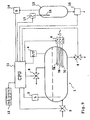
- figure 4 represents a simplified block diagram of a machine for producing hot drinks realised in accordance with the present invention.
- the elements which are functionally equivalent to those of figure 1 are identified with the same reference numerals.
- the machine comprises a saturated steam boiler 1, an exchanger 2, a transducer-indicator 3 of the boiler level, a transducer-indicator of the boiler temperature/pressure parameter, an actuation device 6 of the heating elements 7 of the boiler, a hot water dispenser 9 and coffee dispensing devices 10.
- control system with a central processing unit or CPU 11 and a command keypad 12.
- the components are substantially the same as the independent loop control of figure 1 and they have the same characteristics of flow rate and response time.
- the activation of the dispensing devices 8,9,10 can be controlled by the CPU according to commands received through the keypad 12 (alternatively the keypad 12 can directly command the devices 8,9,10 but at the same time send a corresponding signal to the CPU), so that the CPU can recognise the dispensing operations which are required, can control their execution and, according to the operations in progress or which are orderly programmed and according to the state of the system, it can manage the level and temperature restoring operations in an optimal manner, so as to minimise the reciprocal negative influences linked to the carrying out of the various functions.
- the CPU can anticipate the activation of the level and/or temperature/pressure restore commands, without waiting for the intervention of the level and temperature/pressure sensors, getting rid of the consequent delays.
- the machine fundamentally has three states: inactive (I), active in heating and water reloading (WR&H) and active only in heating (H).
- I inactive
- WR&H active in heating and water reloading
- H active only in heating
- the machine can step to the state H when there is a low pressure condition (LP true) or else if a steam dispensing is activated (SD true)
- the state H does not rule out the possibility of carrying out hot water dispensing: in this case the machine simply does not change its state.
- Figure 5 highlights the complexity of the interactions which develop in the control system of the present invention: in fact the regulation system is even more complex because besides the interaction between water and steam dispensing, level control and pressure/temperature control the CPU intervenes blocking the operation of the boiler or of certain functions in the case of detection of anomalous or inadmissible situations, which are also signalled, for example regarding the level or pressure, which in operating conditions must in any case be contained between a maximum value LM, PM and minimum value Lm, Pm, or even gradients GI (variations in level or pressure in time) which are inconsistent with the operations in progress.
- the state diagram of figure 5 is added to with the addition of a state A of alarm and/or block to which it passes, from one of the other states, when any of the events indicated above occurred (LM,PM, etc.).
- the CPU 11 of figure 4 is programmed to govern the equipment with the following logic:
- diagrams I and II represent in order the temperature of the water in the boiler and the corresponding pressure of the steam at varying times (X-axis) in seconds, respectively in the case of conventional control and in the case of intelligent control, according to the present invention.
- the diagrams WD, SD, WR, H of figure 7 represent, in the same time scale of figure 6, the active state, respectively, of dispensing hot water (WD), dispensing steam (SD), water refill (WR) and heating (H) in the case of conventional control.
- diagrams WD,SD,WR,H of figure 8 represent, in the same time scale of figure 6, the active state, respectively of hot water dispensing (WD), steam dispensing (SD), water refill (WR) and heating (H) in the case of control according to the present invention.
- the temperature of the water and the corresponding pressure in the boiler can be calculated, moment by moment, taking into account the initial thermal content of the boiler, referring to an arbitrary temperature, for example 23°C, the amount of heat subtracted or brought with the different operations (dispensing, refilling, heating) and the amount, variable in time, of the liquid plus steam in which the thermal content of the boiler, also variable in time, is distributed.
- Temperatures of 111°C and 105°C correspond to a relative pressure of about 0.5 e 0.25 bar respectively.
- the flow rate of the steam dispenser is minimal and is between 0.2 and 0.5 Cal/s (0.2-0.5•4.18 kJ).
- the threshold temperature of 120° is reached shortly beforehand, at time t11 (about 147 s from the start) and for the inertia of the transducer the heating is interrupted at time t12, after 157 s from the start, when the temperature of the water is slightly greater than 123°C (about 123.5°C).
- the CPU immediately associates the activation of the refill command of the boiler with the dispensing process without waiting for the signal from the transducer 3.
- the CPU shall continue to monitor the state of the transducers 3 and 4 which must in any case signal the lack of water and/or anomalous pressure conditions within a defined safety time.
- this temperature is detected by the transducer 4 and is transmitted to the CPU which, so as not to make the pressure/temperature fall further, stops the refilling process, keeping just the heating active.
- the CPU recognises the restoration of the normal conditions and reactivates the water refill operation. In the mean time the temperature in the boiler has risen further, to about 124°C.
- the steam dispensing takes place with an optimal pressure in the boiler, which initially corresponds to a steam flow rate, expressed in calories/sec equal to about 1.3 Cal/s (5.44 kW), thus greater than the heating power installed.
- the CPU then suspends the cold water refill process for all of the time in which the steam dispensing is in progress, keeping the heating active.
- the CPU Since the temperature is greater than that of the threshold, the CPU reactivates the water reintegration process in the boiler and the temperature starts to fall again.
- the threshold temperature is again exceeded and, with the hysteresis due to the transducer, at a time t10 which is set at around 130 s from the start the CPU stops the heating process and goes into inactive state awaiting new commands.
- the duration of the cycle was 2 minutes and 10 seconds, therefore shorter than the previous case and the heating of the milk was carried out in just 31 seconds, with the machine still in normal working conditions and capable of simultaneously offering other services to the operations carried out, like coffee dispensing, with repeatable results, because they are not influenced by appreciable variations in temperature.
- control logic described with reference to a boiler like the one of figure 4A also has an advantageous use in the case of a machine for hot drinks in which the dispensing of the coffee takes place from one or more auxiliary heaters, each heated by its heating element.
- Figure 9 represents a block diagram of a machine of this type.
- the machine of figure 9 comprises at least one auxiliary heater 13 (preferably two), for heating the water intended for preparing coffee.
- the capacity of the heater is 0.9 l.
- the heater 13 is equipped with a temperature transducer 14, which typically has a response delay of 10 seconds, with a coffee dispensing device 10, with a heating element 15, with a power of 1.5 kW, supplied through a switch device 17.
- the entry of water into the heater takes place automatically by depression in the heater, concurrently with the dispensing.
- the CPU if the machine is in heating state H of the -boiler, immediately before commanding the activation of the heating element of the auxiliary heater 13, can control the power absorbed by the boiler excluding one or more of the heating elements 7A, 7B, 7C thereof so as to limit the cumulative electrical power absorbed at a predetermined value.
- the transducer 14 can detect a temperature of the heater which is less than a predetermined lower threshold value.
- the transducer 17 instead of directly activating the switch device 17, the transducer 17 sends the information to the CPU which, before activating the heating element 15, verifies the active/inactive state of the different heating elements 7A, 7B, 7C of the boiler.
- the CPU 11 verifies that the heating element 15 is not active.
Landscapes
- Engineering & Computer Science (AREA)
- Food Science & Technology (AREA)
- Control Of Steam Boilers And Waste-Gas Boilers (AREA)
- Apparatus For Making Beverages (AREA)
- Heat Treatment Of Water, Waste Water Or Sewage (AREA)
- Bakery Products And Manufacturing Methods Therefor (AREA)
- Heat-Pump Type And Storage Water Heaters (AREA)
Abstract
Description
- together with the control criteria outlined above the electrical power absorbed can be limited, as proposed in US-A-5,408,917.
- figure 1 is a block diagram of a machine for preparing hot drinks of the prior art;
- figure 2 is a state diagram which describes the level reintegration function in the machine of figure 1;
- figure 3 is a state diagram which describes the pressure/temperature restoring function in the machine of figure 1;
- figure 4 is a block diagram of a machine for preparing hot drinks in accordance with the present invention;
- figure 5 is a state diagram which describes the operation of the machine of figure 4;
- figure 6 is a comparative time diagram of the evolution of the temperature/pressure in the machines of figures 1 and 4 during the course of an example of an operating cycle, which is identical for both machines;
- figure 7 is a time diagram which shows, with reference to the operating cycle of figure 6, the different steps of activity of the machine of figure 1;
- figure 8 is a time diagram which shows, with reference to the operating cycle of figure 6, the different steps of activity of the machine of figure 4;
- figure 9 is a block diagram of a variant of the machine of figure 4.
- volume of the boiler 1: 5 litres,
- volume of water at normal level (HL): 3 litres,
- volume occupied by steam: 2 litres,
- heating power of the boiler: 4500 W (1,075 Cal/s),
- operating pressure (HP) : 1.2 bar, corresponding to a temperature of about 123°C
- flow rate of the boiler refill device 5: 0.014 1/s,
- flow rate of hot water dispenser: 2 1/min (0.033 1/s)
- average response delay of the boiler level and pressure/temperature transducers-indicators: 10 s.
- HL level in the boiler normal (high),
- HP pressure in the boiler normal (high),
- LL level in the boiler low,
- LP pressure in the boiler low,
- WD active hot water dispenser signal, .
- SD active steam dispenser signal,
The symbol "+" has the meaning of OR logic operator.
The letter "N" which precedes an acronym has the meaning of inversion logic operator (NOT).
- when the
hot water dispenser 8 is activated the heating command and the boiler refill command is also immediately activated, i.e. the machine steps from the state I to the state WR&H (fig.5). - to ensure safety, the CPU continues to monitor the
pressure/
temperature sensor transducer 4 and thelevel sensor 3. The first must not in any case signal that a maximum safety pressure PM has been exceeded. Moreover, since the simultaneity of the dispensing process with a flow rate of 0.033 litres/s and of the refilling process with a flow rate of 0.014 1/s produces a negative balance, within a certain maximum period of time the second must detect the lowering of the boiler level. If this does not happen due to some abnormal operation, theCPU 11 has to appropriately signal the problem through the suitable output interfaces (display, sound warnings etc.) and has to deactivate the commands which can leads to situations of malfunction.
- If the
transducer 4 detects a lowering in the boiler pressure below the minimum efficiency threshold for steam dispensing, for example 1 bar, the CPU deactivates the refill command (the machine steps to state H of fig.5) to reactivate it (and to return to the state WR&H of fig. 5) only when the pressure has once again risen to the upper efficiency threshold HP, for example 1.2 bar.
In this way it is avoided that the entry of cold water in a single solution overly absorbs the heat produced by the heating resistances, causing a fall in pressure which would preclude a possible steam dispensing. The internal atmosphere of the boiler always remains ready to respond efficiently to the requirements of the dispensers, water or steam, subordinated to the single condition that the water level in the boiler does not fall below Lm. - also in this case the CPU keeps a surveillance
over the possible abnormal operations taking into account
a safety time out, for example 5 minutes, beyond which the
pressure must anyhow rise to normal operating values and
the refill must be completed.
To fully appreciate the advantages of the invention figures 6,7,8 jointly show a time diagram, for immediate comparison, of the behaviour of a conventional machine, like the one of figure 1 and that of a machine like the one of figure 4, having the same thermal characteristics, already specified, but controlled in an intelligent manner according to the invention.
could input water: 0.014•(30+16)= 0.63 litres
liquid in the boiler: 2.63 litres
heat drawn out by dispensing: 100 Cal (4,18.100 kJ)
input heat: 1.075•60 = 64.5 Cal
final thermal content: 264.5 Cal (4.18•264.5 kJ)
Claims (3)
- Machine for producing hot water, steam and hot drinks, of the type comprising a saturated steam accumulation boiler (1), a steam dispensing lance (9), a hot water dispenser (8), a first transducer (3) for monitoring the water level in the boiler, a second transducer (4) for monitoring a pressure/temperature paramiter in the boiler, at least one heating element (7) of the water in the boiler, a refill device (5) of the water in the boiler, a command device (6) of the heating element, a control system (11,12) with a central processing unit (12) which, in response to the activation of a hot water dispensing operation, immediately activates said command device (6) of the heating element (7) and, if the temperature/pressure parameter in the boiler, monitored by said said second transducer (4), is greater than a predetermined lower threshold value (LP), also activates said refill device (5), keeping it active in the time intervals in which the temperature/pressure parameter in the boiler, monitored by said second transducer (4) is greater than said lower threshold value (LP), until the restoration of a high level (HL) of water in the boiler recognised by said first transducer (3) and deactivating said command device (6) of the heating element (7) only when the water level in the boiler has been restored and the pressure/temperature of the boiler, monitored by said second transducer (4) exceeds a predetermined upper threshold value (HP),
characterised in that said control system, in response to the activation of a steam dispensing operation, immediately activates said command device (6) of the heating element (7), and in that said control system, in response to the activation of a steam dispensing operation when said refill device (5) is active, immediately deactivates said refill device (5) and keeps it inactive for all of the time in which the steam dispensing is in progress. - Machine according to claim 1, wherein said upper threshold value (HP) is equal to said lower threshold value (LP).
- Machine according to claims 1 and 2, further comprising a plurality of heating elements (7A, 7B, 7C) of the boiler water and at least one auxiliary water heater (13), equipped with a water dispenser (10), with a temperature transducer (14), with a heating element (15) and with a command device (17) of the heating element (15), wherein said control system subordinates the joint activation of all of the heating elements (7A, 7B, 7C) of the boiler water (1) upon the condition that the heating element (15) of the auxiliary heater (13) is inactive and rules out the activation of at least one of the heater elements of the boiler water if the activation of the heating element of the auxiliary heater is required.
Applications Claiming Priority (1)
| Application Number | Priority Date | Filing Date | Title |
|---|---|---|---|
| PCT/IT2002/000476 WO2004008926A1 (en) | 2002-07-19 | 2002-07-19 | Machine for the production of hot water, steam and hot drinks |
Publications (2)
| Publication Number | Publication Date |
|---|---|
| EP1523263A1 EP1523263A1 (en) | 2005-04-20 |
| EP1523263B1 true EP1523263B1 (en) | 2005-12-14 |
Family
ID=30471475
Family Applications (1)
| Application Number | Title | Priority Date | Filing Date |
|---|---|---|---|
| EP02765327A Expired - Lifetime EP1523263B1 (en) | 2002-07-19 | 2002-07-19 | Machine for the production of hot water, steam and hot drinks |
Country Status (5)
| Country | Link |
|---|---|
| EP (1) | EP1523263B1 (en) |
| AT (1) | ATE312543T1 (en) |
| DE (1) | DE60208084T2 (en) |
| ES (1) | ES2253554T3 (en) |
| WO (1) | WO2004008926A1 (en) |
Cited By (3)
| Publication number | Priority date | Publication date | Assignee | Title |
|---|---|---|---|---|
| EP2050372A1 (en) * | 2007-10-19 | 2009-04-22 | Gruppo Cimbali S.p.A. | Coffee machine with control of the dispensing temperature by means of a heat exchanger and controlled mixing |
| CN105182894A (en) * | 2015-09-21 | 2015-12-23 | 山东格瑞蓝热能设备有限公司 | Remote control system and method for heat energy equipment |
| TWI671048B (en) * | 2013-04-11 | 2019-09-11 | 美商莫得巴爾公司 | Modular beverage making and dispensing apparatus |
Families Citing this family (9)
| Publication number | Priority date | Publication date | Assignee | Title |
|---|---|---|---|---|
| WO2009000039A1 (en) * | 2007-06-26 | 2008-12-31 | Sunbeam Corporation Limited | A dual heater appliance such as a coffee machine |
| CN101498468B (en) * | 2009-02-17 | 2010-06-02 | 中国安全生产科学研究院 | Boiler and heat exchange station intelligent monitoring system |
| WO2016026327A1 (en) * | 2014-08-20 | 2016-02-25 | 佛山市顺德区美的饮水机制造有限公司 | Drinking water apparatus and quantitative water supply device therefor |
| CN104697578A (en) * | 2015-02-09 | 2015-06-10 | 杭州市特种设备检测研究院 | PLC based universal boiler internet of things monitoring signal acquisition system |
| CN105204429B (en) * | 2015-11-11 | 2018-03-30 | 天津市鑫鼎源科技发展有限公司 | A kind of industrial Multi-parameter data remote transmission device |
| RU180069U1 (en) * | 2017-10-27 | 2018-05-31 | Общество с ограниченной ответственностью "ГУФО" | COFFEE MACHINE |
| GB2576379B (en) | 2018-08-17 | 2021-05-12 | Lavazza Professional Uk Ltd | Beverage dispensing apparatus and method |
| CN109091013B (en) * | 2018-10-30 | 2021-03-16 | 四川爱创科技有限公司 | Dry burning prevention method for coffee machine system during starting |
| CN109044112B (en) * | 2018-10-30 | 2021-03-16 | 四川爱创科技有限公司 | Water-saving dry-burning preventing method for coffee machine system during starting |
Family Cites Families (2)
| Publication number | Priority date | Publication date | Assignee | Title |
|---|---|---|---|---|
| GB1470524A (en) * | 1973-08-09 | 1977-04-14 | Still Sons Ltd W | Water boilers |
| US5372061A (en) * | 1993-04-14 | 1994-12-13 | Avanti Espresso U.S.A., Inc. | Espresso/cappuccino apparatus and method |
-
2002
- 2002-07-19 WO PCT/IT2002/000476 patent/WO2004008926A1/en not_active Ceased
- 2002-07-19 EP EP02765327A patent/EP1523263B1/en not_active Expired - Lifetime
- 2002-07-19 DE DE60208084T patent/DE60208084T2/en not_active Expired - Lifetime
- 2002-07-19 AT AT02765327T patent/ATE312543T1/en active
- 2002-07-19 ES ES02765327T patent/ES2253554T3/en not_active Expired - Lifetime
Cited By (3)
| Publication number | Priority date | Publication date | Assignee | Title |
|---|---|---|---|---|
| EP2050372A1 (en) * | 2007-10-19 | 2009-04-22 | Gruppo Cimbali S.p.A. | Coffee machine with control of the dispensing temperature by means of a heat exchanger and controlled mixing |
| TWI671048B (en) * | 2013-04-11 | 2019-09-11 | 美商莫得巴爾公司 | Modular beverage making and dispensing apparatus |
| CN105182894A (en) * | 2015-09-21 | 2015-12-23 | 山东格瑞蓝热能设备有限公司 | Remote control system and method for heat energy equipment |
Also Published As
| Publication number | Publication date |
|---|---|
| EP1523263A1 (en) | 2005-04-20 |
| WO2004008926A1 (en) | 2004-01-29 |
| ATE312543T1 (en) | 2005-12-15 |
| DE60208084T2 (en) | 2006-08-17 |
| ES2253554T3 (en) | 2006-06-01 |
| DE60208084D1 (en) | 2006-01-19 |
Similar Documents
| Publication | Publication Date | Title |
|---|---|---|
| WO2004008926A1 (en) | Machine for the production of hot water, steam and hot drinks | |
| CA2116580C (en) | Appliance for preparation of hot drinks | |
| AU2011278542B2 (en) | Advanced heating device | |
| EP2571411B1 (en) | Device for heating water and producing steam | |
| CN103750734B (en) | A kind of steam cabinet intelligent control device | |
| JP2001507271A (en) | Steam iron predicts power control | |
| WO2019060371A1 (en) | System and method for operating a grid controlled water heater | |
| AU2008202833B2 (en) | Dual heater appliance such as a coffee machine | |
| CA2885694A1 (en) | Methods and systems for remotely managing water heating units in a water heater to address grid imbalances and related water heaters and circuits | |
| JPS61154631A (en) | Boiling and cooking process control apparatus | |
| EP2489290B1 (en) | An improved system for heating the water in a boiler and a respective method | |
| EP3057480B1 (en) | Apparatus and method for managing water levels in a boiler of a coffee machine | |
| EP1442688B1 (en) | Water heating appliances | |
| WO2015010006A1 (en) | Methods and systems for remotely managing water heating units in a water heater to address grid imbalances and related water heaters and circuits | |
| AU2014335804A1 (en) | Apparatus and method for managing water levels in a boiler of a coffee machine | |
| US20250031900A1 (en) | Machine for dispensing an infusion beverage and related method | |
| CN117722592A (en) | Stable liquid gas supply heating device | |
| JP7483209B2 (en) | Electric water heater system | |
| JP4006538B2 (en) | Steam supply system with backup boiler | |
| JPS61251996A (en) | Cup beverage vending machine | |
| JP2004288160A (en) | Control method of drink regulator | |
| JPH04288446A (en) | electric water heater system | |
| CN100333674C (en) | Appt.and method for preparing coffee-base beverage | |
| JP5034433B2 (en) | Vending machine control equipment | |
| JPS61282992A (en) | Cup beverage vending machine |
Legal Events
| Date | Code | Title | Description |
|---|---|---|---|
| PUAI | Public reference made under article 153(3) epc to a published international application that has entered the european phase |
Free format text: ORIGINAL CODE: 0009012 |
|
| 17P | Request for examination filed |
Effective date: 20041029 |
|
| AK | Designated contracting states |
Kind code of ref document: A1 Designated state(s): AT BE BG CH CY CZ DE DK EE ES FI FR GB GR IE IT LI LU MC NL PT SE SK TR |
|
| 17Q | First examination report despatched |
Effective date: 20050420 |
|
| GRAP | Despatch of communication of intention to grant a patent |
Free format text: ORIGINAL CODE: EPIDOSNIGR1 |
|
| GRAP | Despatch of communication of intention to grant a patent |
Free format text: ORIGINAL CODE: EPIDOSNIGR1 |
|
| GRAS | Grant fee paid |
Free format text: ORIGINAL CODE: EPIDOSNIGR3 |
|
| GRAA | (expected) grant |
Free format text: ORIGINAL CODE: 0009210 |
|
| RAP1 | Party data changed (applicant data changed or rights of an application transferred) |
Owner name: GRUPPO CIMBALI S.P.A. |
|
| AK | Designated contracting states |
Kind code of ref document: B1 Designated state(s): AT BE BG CH CY CZ DE DK EE ES FI FR GB GR IE IT LI LU MC NL PT SE SK TR |
|
| PG25 | Lapsed in a contracting state [announced via postgrant information from national office to epo] |
Ref country code: CZ Free format text: LAPSE BECAUSE OF FAILURE TO SUBMIT A TRANSLATION OF THE DESCRIPTION OR TO PAY THE FEE WITHIN THE PRESCRIBED TIME-LIMIT Effective date: 20051214 Ref country code: NL Free format text: LAPSE BECAUSE OF FAILURE TO SUBMIT A TRANSLATION OF THE DESCRIPTION OR TO PAY THE FEE WITHIN THE PRESCRIBED TIME-LIMIT Effective date: 20051214 Ref country code: SK Free format text: LAPSE BECAUSE OF FAILURE TO SUBMIT A TRANSLATION OF THE DESCRIPTION OR TO PAY THE FEE WITHIN THE PRESCRIBED TIME-LIMIT Effective date: 20051214 Ref country code: BE Free format text: LAPSE BECAUSE OF FAILURE TO SUBMIT A TRANSLATION OF THE DESCRIPTION OR TO PAY THE FEE WITHIN THE PRESCRIBED TIME-LIMIT Effective date: 20051214 Ref country code: FI Free format text: LAPSE BECAUSE OF FAILURE TO SUBMIT A TRANSLATION OF THE DESCRIPTION OR TO PAY THE FEE WITHIN THE PRESCRIBED TIME-LIMIT Effective date: 20051214 |
|
| REG | Reference to a national code |
Ref country code: GB Ref legal event code: FG4D |
|
| REG | Reference to a national code |
Ref country code: CH Ref legal event code: EP |
|
| REG | Reference to a national code |
Ref country code: IE Ref legal event code: FG4D |
|
| REF | Corresponds to: |
Ref document number: 60208084 Country of ref document: DE Date of ref document: 20060119 Kind code of ref document: P |
|
| REG | Reference to a national code |
Ref country code: CH Ref legal event code: NV Representative=s name: RIEDERER HASLER & PARTNER PATENTANWAELTE AG |
|
| PG25 | Lapsed in a contracting state [announced via postgrant information from national office to epo] |
Ref country code: GR Free format text: LAPSE BECAUSE OF FAILURE TO SUBMIT A TRANSLATION OF THE DESCRIPTION OR TO PAY THE FEE WITHIN THE PRESCRIBED TIME-LIMIT Effective date: 20060314 Ref country code: BG Free format text: LAPSE BECAUSE OF FAILURE TO SUBMIT A TRANSLATION OF THE DESCRIPTION OR TO PAY THE FEE WITHIN THE PRESCRIBED TIME-LIMIT Effective date: 20060314 Ref country code: DK Free format text: LAPSE BECAUSE OF FAILURE TO SUBMIT A TRANSLATION OF THE DESCRIPTION OR TO PAY THE FEE WITHIN THE PRESCRIBED TIME-LIMIT Effective date: 20060314 Ref country code: SE Free format text: LAPSE BECAUSE OF FAILURE TO SUBMIT A TRANSLATION OF THE DESCRIPTION OR TO PAY THE FEE WITHIN THE PRESCRIBED TIME-LIMIT Effective date: 20060314 |
|
| PG25 | Lapsed in a contracting state [announced via postgrant information from national office to epo] |
Ref country code: PT Free format text: LAPSE BECAUSE OF FAILURE TO SUBMIT A TRANSLATION OF THE DESCRIPTION OR TO PAY THE FEE WITHIN THE PRESCRIBED TIME-LIMIT Effective date: 20060515 |
|
| NLV1 | Nl: lapsed or annulled due to failure to fulfill the requirements of art. 29p and 29m of the patents act | ||
| REG | Reference to a national code |
Ref country code: ES Ref legal event code: FG2A Ref document number: 2253554 Country of ref document: ES Kind code of ref document: T3 |
|
| PG25 | Lapsed in a contracting state [announced via postgrant information from national office to epo] |
Ref country code: IE Free format text: LAPSE BECAUSE OF NON-PAYMENT OF DUE FEES Effective date: 20060719 |
|
| PG25 | Lapsed in a contracting state [announced via postgrant information from national office to epo] |
Ref country code: MC Free format text: LAPSE BECAUSE OF NON-PAYMENT OF DUE FEES Effective date: 20060731 |
|
| ET | Fr: translation filed | ||
| PLBE | No opposition filed within time limit |
Free format text: ORIGINAL CODE: 0009261 |
|
| STAA | Information on the status of an ep patent application or granted ep patent |
Free format text: STATUS: NO OPPOSITION FILED WITHIN TIME LIMIT |
|
| 26N | No opposition filed |
Effective date: 20060915 |
|
| PG25 | Lapsed in a contracting state [announced via postgrant information from national office to epo] |
Ref country code: EE Free format text: LAPSE BECAUSE OF FAILURE TO SUBMIT A TRANSLATION OF THE DESCRIPTION OR TO PAY THE FEE WITHIN THE PRESCRIBED TIME-LIMIT Effective date: 20051214 |
|
| PG25 | Lapsed in a contracting state [announced via postgrant information from national office to epo] |
Ref country code: LU Free format text: LAPSE BECAUSE OF NON-PAYMENT OF DUE FEES Effective date: 20060719 Ref country code: TR Free format text: LAPSE BECAUSE OF FAILURE TO SUBMIT A TRANSLATION OF THE DESCRIPTION OR TO PAY THE FEE WITHIN THE PRESCRIBED TIME-LIMIT Effective date: 20051214 |
|
| PG25 | Lapsed in a contracting state [announced via postgrant information from national office to epo] |
Ref country code: CY Free format text: LAPSE BECAUSE OF FAILURE TO SUBMIT A TRANSLATION OF THE DESCRIPTION OR TO PAY THE FEE WITHIN THE PRESCRIBED TIME-LIMIT Effective date: 20051214 |
|
| PG25 | Lapsed in a contracting state [announced via postgrant information from national office to epo] |
Ref country code: IT Free format text: LAPSE BECAUSE OF NON-PAYMENT OF DUE FEES Effective date: 20150719 |
|
| REG | Reference to a national code |
Ref country code: FR Ref legal event code: PLFP Year of fee payment: 15 |
|
| REG | Reference to a national code |
Ref country code: FR Ref legal event code: PLFP Year of fee payment: 16 |
|
| PG25 | Lapsed in a contracting state [announced via postgrant information from national office to epo] |
Ref country code: IT Free format text: LAPSE BECAUSE OF NON-PAYMENT OF DUE FEES Effective date: 20150719 |
|
| PGRI | Patent reinstated in contracting state [announced from national office to epo] |
Ref country code: IT Effective date: 20170710 |
|
| REG | Reference to a national code |
Ref country code: FR Ref legal event code: PLFP Year of fee payment: 17 |
|
| PGFP | Annual fee paid to national office [announced via postgrant information from national office to epo] |
Ref country code: ES Payment date: 20200922 Year of fee payment: 19 Ref country code: FR Payment date: 20200721 Year of fee payment: 19 Ref country code: GB Payment date: 20200727 Year of fee payment: 19 Ref country code: DE Payment date: 20200721 Year of fee payment: 19 |
|
| PGFP | Annual fee paid to national office [announced via postgrant information from national office to epo] |
Ref country code: CH Payment date: 20200721 Year of fee payment: 19 Ref country code: AT Payment date: 20200722 Year of fee payment: 19 |
|
| PGFP | Annual fee paid to national office [announced via postgrant information from national office to epo] |
Ref country code: IT Payment date: 20210720 Year of fee payment: 20 |
|
| REG | Reference to a national code |
Ref country code: DE Ref legal event code: R119 Ref document number: 60208084 Country of ref document: DE |
|
| REG | Reference to a national code |
Ref country code: CH Ref legal event code: PL |
|
| REG | Reference to a national code |
Ref country code: AT Ref legal event code: MM01 Ref document number: 312543 Country of ref document: AT Kind code of ref document: T Effective date: 20210719 |
|
| GBPC | Gb: european patent ceased through non-payment of renewal fee |
Effective date: 20210719 |
|
| PG25 | Lapsed in a contracting state [announced via postgrant information from national office to epo] |
Ref country code: LI Free format text: LAPSE BECAUSE OF NON-PAYMENT OF DUE FEES Effective date: 20210731 Ref country code: GB Free format text: LAPSE BECAUSE OF NON-PAYMENT OF DUE FEES Effective date: 20210719 Ref country code: DE Free format text: LAPSE BECAUSE OF NON-PAYMENT OF DUE FEES Effective date: 20220201 Ref country code: CH Free format text: LAPSE BECAUSE OF NON-PAYMENT OF DUE FEES Effective date: 20210731 Ref country code: AT Free format text: LAPSE BECAUSE OF NON-PAYMENT OF DUE FEES Effective date: 20210719 |
|
| PG25 | Lapsed in a contracting state [announced via postgrant information from national office to epo] |
Ref country code: FR Free format text: LAPSE BECAUSE OF NON-PAYMENT OF DUE FEES Effective date: 20210731 |
|
| REG | Reference to a national code |
Ref country code: ES Ref legal event code: FD2A Effective date: 20220902 |
|
| PG25 | Lapsed in a contracting state [announced via postgrant information from national office to epo] |
Ref country code: ES Free format text: LAPSE BECAUSE OF NON-PAYMENT OF DUE FEES Effective date: 20210720 |