EP1523113A1 - Failure detecting device - Google Patents
Failure detecting device Download PDFInfo
- Publication number
- EP1523113A1 EP1523113A1 EP03741209A EP03741209A EP1523113A1 EP 1523113 A1 EP1523113 A1 EP 1523113A1 EP 03741209 A EP03741209 A EP 03741209A EP 03741209 A EP03741209 A EP 03741209A EP 1523113 A1 EP1523113 A1 EP 1523113A1
- Authority
- EP
- European Patent Office
- Prior art keywords
- failure
- communication terminal
- receiver
- main apparatus
- difference
- Prior art date
- Legal status (The legal status is an assumption and is not a legal conclusion. Google has not performed a legal analysis and makes no representation as to the accuracy of the status listed.)
- Withdrawn
Links
- 230000005540 biological transmission Effects 0.000 claims abstract description 54
- 238000004891 communication Methods 0.000 claims description 74
- 230000002457 bidirectional effect Effects 0.000 claims description 14
- 238000011144 upstream manufacturing Methods 0.000 abstract description 22
- 238000012545 processing Methods 0.000 description 20
- 238000000034 method Methods 0.000 description 7
- 230000003321 amplification Effects 0.000 description 4
- 238000001514 detection method Methods 0.000 description 4
- 238000003199 nucleic acid amplification method Methods 0.000 description 4
- 238000010586 diagram Methods 0.000 description 2
- 238000006243 chemical reaction Methods 0.000 description 1
- 238000012937 correction Methods 0.000 description 1
- 230000007423 decrease Effects 0.000 description 1
- 230000003247 decreasing effect Effects 0.000 description 1
- 238000011156 evaluation Methods 0.000 description 1
- 238000005259 measurement Methods 0.000 description 1
- 238000012544 monitoring process Methods 0.000 description 1
- 230000008054 signal transmission Effects 0.000 description 1
Images



Classifications
-
- H—ELECTRICITY
- H04—ELECTRIC COMMUNICATION TECHNIQUE
- H04B—TRANSMISSION
- H04B17/00—Monitoring; Testing
- H04B17/30—Monitoring; Testing of propagation channels
- H04B17/373—Predicting channel quality or other radio frequency [RF] parameters
-
- H—ELECTRICITY
- H04—ELECTRIC COMMUNICATION TECHNIQUE
- H04B—TRANSMISSION
- H04B17/00—Monitoring; Testing
- H04B17/10—Monitoring; Testing of transmitters
-
- H—ELECTRICITY
- H04—ELECTRIC COMMUNICATION TECHNIQUE
- H04B—TRANSMISSION
- H04B17/00—Monitoring; Testing
- H04B17/10—Monitoring; Testing of transmitters
- H04B17/11—Monitoring; Testing of transmitters for calibration
-
- H—ELECTRICITY
- H04—ELECTRIC COMMUNICATION TECHNIQUE
- H04B—TRANSMISSION
- H04B17/00—Monitoring; Testing
- H04B17/30—Monitoring; Testing of propagation channels
- H04B17/309—Measuring or estimating channel quality parameters
- H04B17/318—Received signal strength
- H04B17/327—Received signal code power [RSCP]
Definitions
- difference checking means determines that some communication terminals fall outside the allowable range, it is determined that failures have occurred in the transmitters/receivers of these communication terminals found to fall outside the allowable range.
Landscapes
- Engineering & Computer Science (AREA)
- Physics & Mathematics (AREA)
- Electromagnetism (AREA)
- Computer Networks & Wireless Communication (AREA)
- Signal Processing (AREA)
- Quality & Reliability (AREA)
- Mobile Radio Communication Systems (AREA)
- Monitoring And Testing Of Transmission In General (AREA)
Abstract
A base station (202) receives, from mobile
stations (2031 - 203N), notifications of transmission
and reception powers thereof, which are input to a
failure detecting part (218) together with the
information about transmission and reception powers of
the main device for the mobile stations. The failure
detecting part (218) obtains upstream and downstream
propagation losses of each one of propagation paths
(2041 - 204N). When the difference between those losses
exceeds a predetermined tolerance, the failure detecting
part (218) determines, based on such an exceeding
difference, which one of the transmitters or receivers
has a failure. In this way, there is no need to provide
any special circuit for detecting a failure of a
transmitter or receiver.
Description
Generally, a failure of a transmitter can be
readily detected by detecting, around the transmitter,
transmission output power actually output from the
transmitter and comparing the power of a transmitted
input signal input to the transmitter with the
transmission output power (Japanese Patent Laid-Open
No. 2000-230737). On the other hand, a failure of a
receiver is considered as follows. Although the
reception power itself of the receiver can be detected
by the output from the receiver, an input signal to the
receiver is very weak, and the input timing of the
signal is not accurately known. Therefore, it is
generally impossible to detect input power to the
receiver. Accordingly, a failure of the receiver cannot
be detected by comparing the input and output powers as
in the case of the transmitter.
Conventionally, therefore, a failure is
detected by monitoring the current consumption of the
receiver or a voltage (bias voltage) set for an
amplifier in each stage of a circuit forming the
receiver, and checking variations in current consumption
or bias voltage.
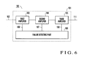
FIG. 6 shows an example of the circuit
configuration of a conventional receiver failure
detecting device. A receiver failure detecting device
100 includes first to third amplifiers 103 to 105 which
input and sequentially amplify a reception signal 102
inside a receiver 101, and a failure detecting part 109
which inputs bias voltages 106 to 108 in predetermined
portions (not shown) of the first to third amplifiers
103 to 105. An amplified reception output 111 is
obtained from the third amplifier 105.
In the receiver failure detecting device 100
as described above, the failure detecting part 109
prestores the bias voltages 106 to 108 when the first to
third amplifiers 103 to 105 are normal. While the
receiver 101 is in operation, the failure detecting part
109 always checks whether the bias voltages are held
within the normal range of the bias voltages 106 to 108,
by using a circuit (not shown) which compares these
voltages. If, as a result of this check, at least one
of the bias voltages 106 to 108 falls outside the normal
range at a certain time, the failure detecting part 109
determines that shortcircuit may have occurred or an
obstacle such as disconnection or burning of a circuit
component may have occurred in a portion of the first
amplifiers 103 to 105, thereby detecting a failure.
In this failure detecting device, different
amplifiers normally have different bias voltages to be
monitored. Accordingly, a plurality of voltage
comparators must be prepared.
Also, to accurately determine a failure, the
voltages of as many circuit portions as possible of one
amplifier must be checked. This increases the number of
voltage comparators required for the failure detecting
device, and increases the cost of the device.
Furthermore, to allow the failure detecting
device to accurately operate, even if the individual
components have variations in characteristics, the
voltage of each part of the receiver must be adjusted
within the range of predetermined values. For example,
even if the amplification factor of the first amplifier
103 of the first to third amplifiers 103 to 106 shown in
Fig. 6 increases, it is difficult to adjust the
amplification factor of the whole by decreasing the
amplification factor of the second amplifier 104 by an
amount corresponding to this increase, and this makes
flexible adjustment difficult, resulting in
time-consuming receiver adjustment.
It is an object of the present invention to
provide a failure detecting device which requires no
special circuit for detecting a failure of a transmitter
or receiver.
A failure detecting device according to the
present invention comprises ( ) notification receiving
means for receiving, from at least one communication
terminal of a communication partner, notification of
both reception power of a signal transmitted from a main
apparatus and transmission power of a signal transmitted
to the main apparatus, (□) determining means for
determining the reception power from the communication
terminal and the transmission power to the communication
terminal, (
) notification receiving
means for receiving, from at least one communication
terminal of a communication partner, notification of
both reception power of a signal transmitted from a main
apparatus and transmission power of a signal transmitted
to the main apparatus, (□) determining means for
determining the reception power from the communication
terminal and the transmission power to the communication
terminal, ( ) propagation loss calculating means for
calculating bidirectional propagation losses between the
communication terminal and main apparatus, from the two
powers output from the notification receiving means and
the two powers output from the determining means, (=)
difference checking means for checking whether a
difference between the propagation losses falls within a
predetermined allowable range, and (
) propagation loss calculating means for
calculating bidirectional propagation losses between the
communication terminal and main apparatus, from the two
powers output from the notification receiving means and
the two powers output from the determining means, (=)
difference checking means for checking whether a
difference between the propagation losses falls within a
predetermined allowable range, and ( ) failure
determining means for determining that a
transmitter/receiver of at least one of the
communication terminal and main apparatus has a failure,
if the difference checking means determines that the
difference falls outside the allowable range.
) failure
determining means for determining that a
transmitter/receiver of at least one of the
communication terminal and main apparatus has a failure,
if the difference checking means determines that the
difference falls outside the allowable range.
An embodiment of the present invention will be
described in detail below.
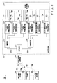
Fig. 1 shows a communication system including
a failure detecting device according to the embodiment
of the present invention. A communication system 200
includes a base station 202 having a base station
antenna 201, and first to Nth mobile stations 2031 to
203N which communicate with the base station 202 by a
CDMA (Code Division Multiple Access) method.
First to Nth propagation paths 2041 to 204N
are formed when signals are exchanged between the base
station antenna 201 and first to Nth mobile stations
2031 to 203N. The propagation losses of the first to
Nth propagation paths 2041 to 204N change in accordance
with the arrangement environment, e.g., the positions of
the first to Nth mobile stations 2031 to 203N. In this
embodiment, however, these propagation losses are
represented by first to Nth propagation losses L1 to LN.
The base station 202 has a duplexer 211
connected to the base station antenna 201. A reception
signal 212 obtained from the base station antenna 201 is
supplied through the duplexer 211, and input to and
received by a receiver 213 connected to the duplexer
211. The output side of the receiver 213 is connected
first to Nth reception signal processing parts 2141 to
214N arranged in one-to-one correspondence with the
first to Nth mobile stations 2031 to 203N.
The first to Nth reception signal processing
parts 2141 to 214N input mobile station transmission
powers Ptm1 to PtmN and mobile station reception powers
Prm1 to PrmN to a failure detecting part 218 connected to
the first to Nth reception signal processing parts 2141
to 214N.
From first to Nth transmission signal
processing parts 2211 to 221N, the failure detecting
part 218 receives base station transmission powers Ptb1
to PtbN corresponding to the first to Nth base stations
2031 to 203N. Also, if a failure occurs in any of the
first to Nth mobile stations 2031 to 203N, the failure
detecting part 218 outputs the corresponding one of
first to Nth failure notification signals 2231 to 223N
to the corresponding one of the first to Nth mobile
stations 2031 to 203N.
The first to Nth transmission signal
processing parts 2211 to 221N are connected to a
transmitter 225. A transmission signal 226 output from
the transmitter 225 is supplied to the base station
antenna 201 via the duplexer 211, and transmitted from
the base station antenna 201 to the first to Nth mobile
stations 2031 to 203N via the first to Nth propagation
paths 2041 to 204N.
In the communication system 200 as described
above, transmission signals from the first to Nth mobile
stations 2031 to 203N are received by the base station
202 via the base station antenna 201. The received
signals are separated from the transmission signal 226
by the duplexer 211, and input as reception signals 212
to the receiver 213. The receiver 213 converts the
reception signals 212, transmitted from the first to Nth
mobile stations 2031 to 203N and received by the base
station 202, into a frequency which can undergo signal
processing, and amplifies the converted signals to a
predetermined power. The first to Nth reception signal
processing parts 2141 to 214N despread the amplified
signals, and extract the mobile station signals
transmitted from the mobile stations 2031 to 203N. The
first to Nth reception signal processing parts 2141 to
214N detect the reception powers of these extracted
reception signals. The detected reception powers are
represented by base station reception powers Prb1 to
PrbN.
In the communication system 200, the first to
Nth mobile stations 2031 to 203N detect the transmission
powers transmitted from them to the base station 202 and
the reception powers of the transmission signal 226
transmitted from the base station 202, and transmit the
detection results to the base station 202 when
transmitting signals.
The first to Nth reception signal processing
parts 2141 to 214N demodulate and extract information
about the mobile station transmission powers Ptm1 to PtmN
and mobile station reception powers Prm1 to PrmN
transmitted from the first to Nth mobile stations 2031
to 203N. The first to Nth reception signal processing
parts 2141 to 214N supply, to the failure detecting part
218, the mobile station transmission powers Ptm1 to PtmN
and mobile station reception powers Prm1 to PrmN together
with the base station reception powers Prb1 to PrbN.
Also, the base station 202 supplies, to the
failure detecting part 218, the base station
transmission powers Ptb1 to PtbN transmitted from the
transmitter 225 via the first to Nth transmission signal
processing parts 2211 to 221N.
Fig. 2 shows the relationship between these
four types of powers of the mobile station and base
station. That is, Fig. 2 shows the relationship between
an arbitrary mobile station X, an Xth upstream
propagation path 204Xn, an Xth downstream propagation
path 204Xd, and the base station.
The failure detecting part 218 shown in Fig. 1
calculates the propagation loss between the base station
202 and mobile station 203X by using base station
reception power PrbX, base station transmission power
PtbX, mobile station transmission power PtmX, and mobile
station reception power PrmX.
Also, the failure detecting part 218 compares
the results of calculations by the first to Nth mobile
stations 2031 to 203N. In this manner, the failure
detecting part 218 detects a failure of the receiver 213
of the base station 202 or a failure of any of the
mobile stations 2031 to 203N. This will be explained in
detail later.
If the failure detecting part 218 detects a
failure of any station, and if this failure concerns any
of the first to Nth transmission signal processing parts
2211 to 221N, the base station 202 notifies the
corresponding mobile station 203 of the failure.
This notification indicating that the failure
is found is supplied from the failure detecting part 218
to the portion corresponding to the failure in any of
the first to Nth transmission signal processing parts
2211 to 221N, and supplied to the transmitter 225. The
transmitter 225 converts the notification into an RF
signal by frequency conversion, and amplifies the signal
to power necessary for transmission. The amplified
signal is synthesized with the reception signal by the
duplexer 211, and transmitted via the base station
antenna 201. Consequently, the corresponding one of the
first to Nth mobile stations 2031 to 203N can receive
the information indicating that the failure is found.
Details of the failure detecting part 218 will
be described below.
As shown in Fig. 3, the failure detecting part
218 includes a notification receiver 218a which receives
the notification of the mobile station transmission
power Ptmx and mobile station reception power Prmx from
the first to Nth mobile stations 2031 to 203N, and a
determinator 218b which determines the base station
reception power Prbx and base station transmission power
Ptbx extracted from the first to Nth reception signal
processing parts 2141 to 214N.
The failure detecting part 218 also includes a
propagation loss calculator 218c which is connected to
the notification receiver 218a and determinator 218b,
and calculates bidirectional propagation losses between
the first to Nth mobile stations 2031 to 203N and base
station 202, from the mobile station transmission power
Ptmx and mobile station reception power Prmx input from
the notification receiver 218a, and the base station
reception power Prbx and base station transmission power
Ptbx input from the determinator 218b.
In addition, the failure detecting part 218
includes a difference checking unit 218d which is
connected to the propagation loss calculator 218c, and
checks, for each of the first to Nth mobile stations
2031 to 203N, whether the difference between the
bidirectional propagation losses calculated by the
propagation loss calculator 218c falls within an
allowable range.
Furthermore, the failure detecting part 218
includes a failure determinator 218e which is connected
to the difference checking unit 218d, and determines
whether a failure has occurred in a mobile station and
base station for which the difference checking unit 218d
determines that the propagation loss difference falls
outside the allowable range.
The failure detecting part 218 also includes a
failure notification unit 218f which is connected to the
failure determinator 218e, and notifies a mobile station
and base station, found to have a failure by the failure
determinator 218e, of the presence of the failure.
Assume that the mobile station transmission
powers and mobile station reception powers of the N
mobile stations 2031 to 203N shown in Fig. 1 are as
follows. In this state, all the mobile stations 2031 to
203N are normally operating.
Assume that in this state, the base station
transmission powers and base station reception powers of
the base station with respect to the mobile stations
2031 to 203N are as follows. In this state, the base
station is normally operating.
In this example, the failure detecting part
218 can calculate the transmission losses of the
transmission paths 2041 to 204N between the base station
202 and mobile stations 2031 to 203N by using the above
measurement results by
 where symbol X indicates an arbitrary transmission path.
Also, the propagation losses of the mobile
stations 2031 to 203N are calculated by
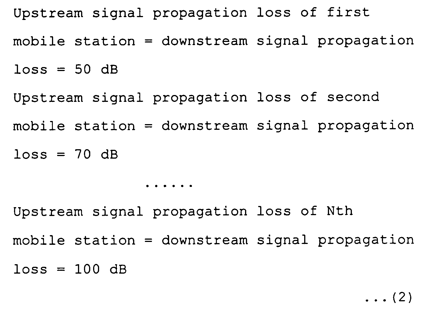
Normally, however, the frequencies of upstream
and downstream signals in the same mobile station 203
are different. Therefore, the upstream and downstream
signal propagation losses take different values. To
simplify the explanation, in this example it is assumed
that the downstream and upstream signal propagation
losses are equal. However, the frequencies of upstream
and downstream signals are known in practice.
Accordingly, the upstream and downstream signal
propagation losses of the same propagation path can be
calculated. Correction of the propagation losses is
also easy.
A case in which the receiver 213 of the base
station 202 fails and as a consequence all the reception
levels of the base station 202 lower by 10 dB will be
explained below. In this state, all the first to Nth
mobile stations 2031 to 203N are normal. Under the
assumption, all the reception powers from the first to
Nth mobile stations 2031 to 203N detected by the base
station 202 lower by 10 dB. However, these reception
powers are not always equal even when the receiver 213
of the base station 202 is normal. Therefore, it is
impossible to determine, from information indicating the
detected reception powers, whether the level of the
receiver 225 has lowered or the input signal levels of
signals transmitted from the first to Nth mobile
stations 2031 to 203N have lowered.
In this embodiment, to perform this
determination, the propagation losses between the base
station 202 and first to Nth mobile stations 2031 to
203N are calculated. Equations (2) presented above are
based on the assumption that the upstream and downstream
signal propagation losses are equal. Accordingly, the
propagation losses of the mobile stations 2031 to 203N
after the receiver 213 of the base station 202 has
failed are indicated by
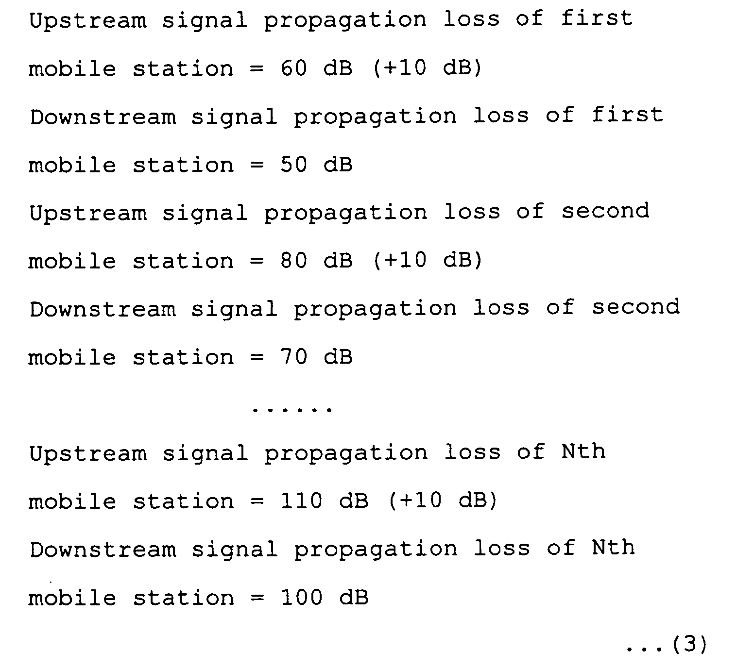
The comparison of equations (3) with equations
(2) shows that in all the first to Nth mobile stations
2031 to 203N, the upstream signal propagation loss
increases by 10 dB from the downstream signal
propagation loss. Consequently, it is determined that
the gain of the receiver 225 of the base station 202
lowers by 10 dB, i.e., the receiver 225 alone has
failed.
Consider a case in which the receiver (not
shown) of the first mobile station 2031 alone fails and
as a consequence the gain lowers by 10 dB will be
described below. In this state, the second to Nth
mobile stations 2032 to 203N and base station 202 are
normal. In this case, the propagation losses of the
mobile stations 2031 to 203N are indicated by

Consequently, it is determined by comparing
equations (4) with equations (2) that the gain of the
receiver of the first mobile station 2031 has lowered by
10 dB, i.e., the receiver of the first mobile station
2031 alone has failed.
Consider a case in which the gains of the base
station 202 and first mobile station 2031 lower by 10 dB
at the same time will be described below. In this
state, all the second to Nth mobile stations 2032 to
203N are normal. In this case, the propagation losses
of the mobile stations 2031 to 203N are indicated by
 where (+ 10dB) indicates the difference from equations
(4). In equations (5) as shown above, the upstream and
downstream signal propagation losses are equal only in
the first mobile station 2031, and the upstream signal
propagation loss is larger by 10 dB than the downstream
signal propagation loss in all the second to Nth mobile
stations 2032 to 203N.
where (+ 10dB) indicates the difference from equations
(4). In equations (5) as shown above, the upstream and
downstream signal propagation losses are equal only in
the first mobile station 2031, and the upstream signal
propagation loss is larger by 10 dB than the downstream
signal propagation loss in all the second to Nth mobile
stations 2032 to 203N.
Normally, the probability that some stations
fail is much higher than the probability that all
stations fail together. Since, therefore, the upstream
signal propagation losses of all the mobile stations
2031 to 203N lower by 10 dB, it is determined that the
gain of the base station 202 has lowered by 10 dB.
Then, it is possible to assume that the number of fault
mobile stations is much smaller than the number of
normal mobile stations, so it is determined that the
gain of the receiver of the first mobile station 2031
has lowered by 10 dB.
In the failure detecting device of this
embodiment, the base station 202 exclusively performs
failure detection. Accordingly, the base station 202
can recognize the status of its own failures and those
of the first to Nth mobile stations 2031 to 203N, but
the first to Nth mobile stations 2031 to 203N cannot
recognize failures by themselves. Therefore, if, for
example, the first mobile station 2031 alone has failed,
the base station 202 outputs this information to the
first transmission signal processing part 2211, and the
transmitter 225 transmits the information to the first
mobile station 2031. As a consequence, the first mobile
station 2031 can recognize the failure of its own
transmitter or receiver, and take a measure to correct
the failure.
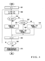
Fig. 4 shows an outline of the flow of a
failure detecting process used in the failure detecting
part according to this embodiment described above. The
failure detecting part 218 shown in Fig. 1 has a CPU
(Central Processing Unit, not shown), and executes the
failure detecting process by executing a predetermined
control program stored in a storage medium such as a ROM
(Read Only Memory, not shown).
First, the failure detecting part 218
initializes a variable n to "1" (step S301). At the
same time, the failure detecting part 218 clears the
contents of a buffer (to be explained later). The
propagation loss calculator 218c calculates an upstream
signal propagation loss Lnu and downstream signal
propagation loss Lnd of an nth mobile station 203n by
equations (1) (step S302). Since the variable n is "1",
an operation indicated by equations (6) below is
actually performed.

Then, the difference checking unit 218d checks
whether the upstream and downstream signal propagation
losses Lnu and Lnd calculated in step S302 fall within
substantially equal ranges (step S303). Although the
difference between the two is "0" in the above
explanation, in this example it is assumed that the
difference between the two is approximated to "0" if it
falls within the range of ±10 dB. If the difference
between the two is "0" (YES), "0" is recorded in that
area of the buffer memory (not shown) where the variable
n is "1", which corresponds to the first mobile station
2031 (step S304).
When this processing is complete, the variable
n is counted up by "1" (step S305), and whether the
variable n is larger than a total number "N" of the
mobile stations 2031 to 203N is checked (step S306). If
the variable n is equal to or smaller than the total
number "N", a mobile station 203 whose transmitter and
receiver are to be checked still remains (NO). In this
case, therefore, the flow returns to step S302 to
proceed to processing for the second mobile station
2032.
On the other hand, if it is determined in step
S303 that the upstream and downstream signal propagation
losses Lnu and Lnd fall outside the allowable ranges, and
if the upstream signal propagation loss Lnu is larger
than the downstream signal propagation loss Lnd (step
S307: YES), "+" is recorded in that portion of the
buffer memory, which corresponds to the variable n (step
S308). The flow then advances to the processing in step
S305. Also, if it is determined in step S303 that the
upstream and downstream signal propagation losses Lnu
and Lnd fall outside the allowable ranges, and if the
upstream signal propagation loss Lnu is smaller than the
downstream signal propagation loss Lnd (step S307: NO),
"-" is recorded in that portion of the buffer memory,
which corresponds to the variable n (step S309). The
flow then advances to the processing in step S305.
In this manner, whether the difference between
the upstream and downstream signal propagation losses
Lnu and Lnd is within the allowable range ("0"), larger
than the allowable range ("+"), or smaller than the
allowable range ("-") is checked for each of the first
to Nth mobile stations 2031 to 203N in order from the
first mobile station 2031. If this check up to the Nth
mobile station 203N is complete in step S306 (YES), the
failure determinator 218e determines the
presence/absence of a failure in the base station 202
and first to Nth mobile stations 2031 to 203N in
accordance with the contents of the buffer memory (step
S310).
Fig. 5 shows details of the process of
determining the presence/absence of a failure of the
transmitter or receiver in step S310 of Fig. 4. First,
if the difference between the upstream and downstream
signal propagation losses Lnu and Lnd is found to fall
within the allowable range ("0") for all the variables
"1" to "n" stored in the buffer memory (step S321: YES),
it is determined that the transmitters and receivers of
all the base station 202 and first to Nth mobile
stations 2031 to 203N are normal (step S322).
Note that if the transmitters and receivers of
all the base station 202 and first to Nth mobile
stations 2031 to 203N have failed, a phenomenon in which
the difference between the upstream and downstream
signal propagation losses Lnu and Lnd falls within the
allowable range ("0") for all the first to Nth mobile
stations 2031 to 203N can occur. However, this
embodiment does not assume such an extremely exceptional
failure mode. Note also that as already described
above, a failure of the transmitter of any of the base
station 202 and first to Nth mobile stations 2031 to
203N can be detected independently of the present
invention. Therefore, failure determination can be
performed more accurately by using the two methods at
the same time, but this will not particularly be
considered below.
If it is determined in step S321 that not all
the variables n fall within the allowable range ("0")
(NO), whether all the variables n are "+" is checked
(step S323). If all the variables n are "+" (YES), the
downstream transmission path propagation loss is larger
than the upstream transmission path propagation loss in
all the stations. This phenomenon can occur when the
transmitter 225 of the base station 202 has failed, or
when the receivers of all the first to Nth mobile
stations 2031 to 203N have failed. However, the
possibility that the receivers of all the first to Nth
mobile stations 2031 to 203N fail at the same time is
extremely low. In this case, therefore, it is
determined that the transmitter 225 of the base station
202 has failed (step S324).
If some variables n are "+" (step S325: YES),
it is determined that the receivers of mobile stations
203 found to be "+" have failed (step S326). In this
case, when the base station 202 transmits a signal to
the mobile stations 203 found to have failed, the
failure notification unit 218f notifies that their
receivers have failed (step S327). Consequently, each
mobile station 203 having received this notification can
recognize the occurrence of the failure by reproducing
the notification by the receiver, and rapidly correct
the failure.
If all the variables n fall outside the
allowable range ("0") and at least some variables n are
not "+" (step S323: NO, and step S325: NO), whether all
the variables n are "-" is checked (step S328). If all
the variables n are "-" (YES), it is determined that the
receiver 213 (Fig. 1) of the base station 202 has failed
(step S329).
Finally, a case in which some variables n are
"-" (step S328: NO) will be explained below. In this
case, it is determined that the transmitters of mobile
stations whose variables n are "-" have failed (step
S330). In this case, as in the above case, when the
base station 202 transmits a signal to the mobile
stations 203 found to have failed, these mobile stations
are notified that their receivers have failed (step
S331). Consequently, each mobile station 203 having
received this notification can recognize the occurrence
of the failure by reproducing the notification by the
receiver, and rapidly correct the failure.
In the embodiment described above, a failure
of the receiver or transmitter is detected by two-stage
evaluation, i.e., by the presence/absence of a failure.
However, the degrees of failures may also be more finely
classified into, e.g., a failure by which the
amplification factor only slightly increases or
decreases, and a failure worse than that. Additionally,
a failure of the transmitter is also determined in the
embodiment. However, only a failure of the receiver can
also be determined.
Although detection of a failure of a mobile
station such as a cell phone is explained in the above
embodiment, the present invention is, of course, also
applicable to other radio apparatuses.
In the above-mentioned embodiment, a source
apparatus, e.g., a base station receives, from a
communication terminal of a communication partner with
which the base station communicates, the notification of
both the reception power of a signal transmitted by the
source apparatus and the transmission power of a signal
transmitted to the source apparatus, determines the
reception power and transmission power of the source
apparatus with respect to the communication terminal,
and calculates bidirectional propagation losses between
the communication terminal and source apparatus on the
basis of these four types of data. The difference
checking means checks whether the difference between the
bidirectional propagation losses falls within a
predetermined allowable range. If the
transmitters/receivers of the two apparatuses are
normal, the bidirectional propagation losses of one
propagation path are equal or fall within the
predetermined allowable range. Therefore, if the
bidirectional propagation losses fall outside the
allowable range, it is determined that either the
communication terminal or source apparatus as the two
ends of the propagation path has a failure. That is, by
detecting the signal transmission power and reception
power of each of the source apparatus and the
communication terminal of the communication partner, the
presence/absence of a failure of the
transmitters/receivers of these two apparatuses can be
determined without using any special hardware.
Also, a failure of a source apparatus which
communicates with a plurality of communication terminals
can be detected. In this case, the source apparatus
receives, from each of these communication terminals,
the notification of the reception power of a signal
transmitted by the source apparatus and the transmission
power of a signal transmitted to the source apparatus,
determines the reception power and transmission power of
the source apparatus with respect to each of these
communication terminals, and calculates bidirectional
propagation losses between each communication terminal
and the source apparatus on the basis of these four
types of data. The difference checking means checks
whether the difference between the bidirectional
propagation losses falls within a predetermined
allowable range. If the transmitters/receivers of the
two apparatuses are normal, the bidirectional
propagation losses of one propagation path are equal or
fall within the predetermined allowable range.
Therefore, for a pair of the source apparatus and a
communication terminal by which the bidirectional
propagation losses fall outside the allowable range, it
is determined that either the communication terminal or
source apparatus has a failure. It is also possible to
perform more precise failure detection on the basis of
the correlation with a plurality of communication
terminals. That is, when communicating with a plurality
of communication terminals, the source apparatus
calculates propagation losses between these
communication terminals and the source apparatus, and
determines that a failure has occurred in the
transmitter/receiver of one of a communication terminal
and the source apparatus by which the difference between
the bidirectional propagation losses falls outside the
predetermined allowable range, so the presence/absence
of a failure of these apparatuses can be determined
without using any special hardware.
In addition, if the difference checking means
determines that all the communication terminals fall
outside the allowable range, all these communication
terminals may have failed or the source apparatus may
have failed. However, if the failure rates of the
source apparatus and each communication terminal are
equal, the probability that the source apparatus fails
is higher than the probability that all the
communication terminals fail. In this case, therefore,
it is determined that the transmitter/receiver of the
source apparatus has failed.
If the difference checking means determines
that some communication terminals fall outside the
allowable range, it is determined that failures have
occurred in the transmitters/receivers of these
communication terminals found to fall outside the
allowable range.
Also, if it is determined that the
transmitter/receiver of the source apparatus has failed,
more precise failure determination is performed. That
is, if the propagation loss of a propagation path to the
source apparatus is smaller than that of a propagation
path to each communication terminal, it is determined
that the receiver of the source apparatus has failed.
In the opposite case, it is determined that the
transmitter of the source apparatus has failed. More
specifically, if it is determined that a value obtained
by subtracting the transmission power of the source
apparatus with respect to a communication terminal from
the reception power of the communication terminal is
larger than a value obtained by subtracting the
transmission power of the communication terminal from
the reception power of the source apparatus with respect
to the communication terminal, it is determined that the
receiver of the source apparatus has failed. Otherwise,
it is determined that the transmitter of the source
apparatus has failed.
Likewise, if it is determined that the
transmitter or receiver of the communication terminal
has failed, more precise failure determination is
performed. That is, if the propagation loss of a
propagation path to the source apparatus is smaller than
that of a propagation path to each communication
terminal, it is determined that the transmitter of a
communication terminal found to fall outside the
allowable range has failed. Otherwise, it is determined
that the receiver of the communication terminal found to
fall outside the allowable range has failed. More
specifically, determination is performed on the basis of
the relationship between a value obtained by subtracting
the transmission power of a communication terminal from
the reception power of the source apparatus with respect
to the communication terminal and a value obtained by
subtracting the transmission power of the source
apparatus with respect to the communication terminal
from the reception power of the communication terminal.
Furthermore, although the source apparatus
determines a failure, if the source apparatus determines
that a communication terminal has failed, the source
apparatus notifies the communication terminal of the
failure. Accordingly, the corresponding communication
terminal can recognize that its receiver or the like has
failed, and take a necessary countermeasure.
As described above, the failure detecting
device according to the present invention which detects
a failure of a circuit apparatus such as a receiver is
suited to detecting a failure of a receiver such as a
base station receiver or a receiver of a mobile
terminal.
Claims (8)
- A failure detecting device characterized by comprising:notification receiving means for receiving, from at least one communication terminal of a communication partner, notification of both reception power of a signal transmitted from a main apparatus and transmission power of a signal transmitted to said main apparatus;determining means for determining the reception power from said communication terminal and the transmission power to said communication terminal;propagation loss calculating means for calculating bidirectional propagation losses between said communication terminal and main apparatus, from the two powers output from said notification receiving means and the two powers output from said determining means;difference checking means for checking whether a difference between the propagation losses falls within a predetermined allowable range; andfailure determining means for determining that a transmitter/receiver of at least one of said communication terminal and main apparatus has a failure, if said difference checking means determines that the difference falls outside the allowable range.
- A failure detecting device according to claim 1, characterized by further comprising a plurality of communication terminals,
wherein said notification receiving meansreceives, from each of said plurality of communication terminals of a communication partner, notification of both reception power of a signal transmitted from said main apparatus and transmission power of a signal transmitted to said main apparatus,said determining means determines, for each communication terminal, the reception powers from said plurality of communication terminals and the transmission powers to said plurality of communication terminals,said propagation loss calculating means calculates bidirectional propagation losses between each communication terminal and said main apparatus, from the two powers output from said notification receiving means and the two powers output from said determining means,said difference checking means checks whether a difference between the propagation losses falls within a predetermined allowable range, andsaid failure determining means determines that a transmitter/receiver of at least one of said communication terminal and main apparatus has a failure, if said difference checking means determines that the difference falls outside the allowable range. - A failure detecting device according to claim 2, characterized in that if said difference checking means determines that the difference falls outside the allowable range for all of said plurality of communication terminals, said failure determining means determines that a transmitter/receiver of said main apparatus has a failure.
- A failure detecting device according to claim 2, characterized in that if said difference checking means determines that the difference falls outside the allowable range for some of said plurality of communication terminals, said failure determining means determines that a transmitter/receiver of each of said communication terminals, which is found to fall outside the allowable range has a failure.
- A failure detecting device according to claim 3, characterized in that if it is determined that a propagation loss of a propagation path to said main apparatus is smaller than a propagation loss of a propagation path to each communication terminal, said failure determining means determines that a receiver of said main apparatus has failed, and, otherwise, said failure determining means determines that a transmitter of said main apparatus has failed.
- A failure detecting device according to claim 4, characterized in that if it is determined that a propagation loss of a propagation path to said main apparatus is smaller than a propagation loss of a propagation path to each communication terminal, said failure determining means determines that a transmitter of a communication terminal found to fall outside the allowable range has failed, and, otherwise, said failure determining means determines that a receiver of a communication terminal found to fall outside the allowable range has failed.
- A failure detecting device according to claim 1, characterized in that if it is determined that a propagation loss of a propagation path to said main apparatus is equal to a propagation loss of a propagation path to each communication terminal, said failure determining means determines that said communication terminal and main apparatus are normal.
- A failure detecting device according to claim 1, characterized by further comprising failure notifying means for notifying said communication terminal of a detected failure.
Applications Claiming Priority (3)
| Application Number | Priority Date | Filing Date | Title |
|---|---|---|---|
| JP2002207307A JP4048855B2 (en) | 2002-07-16 | 2002-07-16 | Failure detection device |
| JP2002207307 | 2002-07-16 | ||
| PCT/JP2003/008557 WO2004008661A1 (en) | 2002-07-16 | 2003-07-04 | Failure detecting device |
Publications (1)
| Publication Number | Publication Date |
|---|---|
| EP1523113A1 true EP1523113A1 (en) | 2005-04-13 |
Family
ID=30112817
Family Applications (1)
| Application Number | Title | Priority Date | Filing Date |
|---|---|---|---|
| EP03741209A Withdrawn EP1523113A1 (en) | 2002-07-16 | 2003-07-04 | Failure detecting device |
Country Status (6)
| Country | Link |
|---|---|
| US (1) | US20050209806A1 (en) |
| EP (1) | EP1523113A1 (en) |
| JP (1) | JP4048855B2 (en) |
| KR (1) | KR100629287B1 (en) |
| CN (1) | CN100495948C (en) |
| WO (1) | WO2004008661A1 (en) |
Cited By (1)
| Publication number | Priority date | Publication date | Assignee | Title |
|---|---|---|---|---|
| EP2830349A1 (en) * | 2013-07-22 | 2015-01-28 | Siemens S.A.S. | Devices and method for automatic detection of a failure of a radio transceiver |
Families Citing this family (12)
| Publication number | Priority date | Publication date | Assignee | Title |
|---|---|---|---|---|
| CN101291176B (en) * | 2007-04-18 | 2012-07-04 | 华为技术有限公司 | Fault detection method, system and apparatus for optical distributed network |
| US8995829B2 (en) * | 2007-06-05 | 2015-03-31 | Cisco Technology, Inc. | Optical link quality monitoring in a computer network |
| JP4983439B2 (en) * | 2007-06-29 | 2012-07-25 | 三菱電機株式会社 | Data communication method |
| CN102036278A (en) * | 2009-09-27 | 2011-04-27 | 中兴通讯股份有限公司 | Base station receiving channel fault positioning method and base station |
| KR101500299B1 (en) * | 2010-08-17 | 2015-03-18 | 에스케이텔레콤 주식회사 | Remote repair system and method |
| CN102711161B (en) * | 2012-06-25 | 2016-07-13 | 华为技术有限公司 | Alarm method and device |
| JP6104615B2 (en) * | 2013-01-23 | 2017-03-29 | 株式会社東芝 | Failure detection apparatus and method |
| CN106028387B (en) * | 2016-06-30 | 2019-08-20 | 维沃移动通信有限公司 | A kind of collection method and mobile terminal of communication abnormality |
| KR102443062B1 (en) * | 2018-03-27 | 2022-09-14 | 삼성전자주식회사 | Apparatus and method for controlling transmission of electronic devices |
| US10819616B2 (en) * | 2019-01-15 | 2020-10-27 | Litepoint Corporation | System and method for testing a data packet signal transceiver |
| US10666542B1 (en) * | 2019-01-15 | 2020-05-26 | Litepoint Corporation | System and method for testing a data packet signal transceiver |
| US12355563B2 (en) | 2022-01-24 | 2025-07-08 | Cisco Technology, Inc. | Correlating transceiver parameters for insight into transceiver health |
Family Cites Families (13)
| Publication number | Priority date | Publication date | Assignee | Title |
|---|---|---|---|---|
| US4807224A (en) * | 1987-08-21 | 1989-02-21 | Naron Steven E | Multicast data distribution system and method |
| JP2503889B2 (en) * | 1993-07-07 | 1996-06-05 | 日本電気株式会社 | Receiver amplifier failure detection method for wireless transceiver |
| US6481005B1 (en) * | 1993-12-20 | 2002-11-12 | Lucent Technologies Inc. | Event correlation feature for a telephone network operations support system |
| SE9401713D0 (en) * | 1994-05-16 | 1994-05-16 | Ericsson Telefon Ab L M | Method to improve measurement accuracy in handover decision |
| JPH10276127A (en) * | 1997-03-28 | 1998-10-13 | Saitama Nippon Denki Kk | Radio base station equipment with fault detection function and mobile communication system using the same |
| CA2238791C (en) * | 1997-08-11 | 2004-07-13 | Nec Corporation | Cdma type mobile radio communication system capable of realizing an effective system operation without excess and deficiency of radio base stations simultaneously connected |
| JP3397677B2 (en) * | 1998-02-10 | 2003-04-21 | 松下電器産業株式会社 | Transmission power control device and wireless communication device |
| JP3125776B2 (en) * | 1998-03-27 | 2001-01-22 | 日本電気株式会社 | Transmission power control method and base station apparatus in cellular system |
| US6278879B1 (en) * | 1998-09-22 | 2001-08-21 | Motorola, Inc. | Method for determining a transmit power of a base station in a cellular communication system |
| GB9902745D0 (en) * | 1999-02-09 | 1999-03-31 | Hewlett Packard Co | Assessing path imbalance in mobile communications networks |
| JP3473555B2 (en) * | 2000-06-30 | 2003-12-08 | 日本電気株式会社 | Transmission power control system, control method, base station, control station, and recording medium |
| DE10055103A1 (en) * | 2000-11-07 | 2002-05-08 | Daimler Chrysler Ag | Operating data network involves defining current level reserve for overdriving limit, that is between current transmitter power and current receiver overdriving limit, for test mode |
| JP3844957B2 (en) * | 2000-11-15 | 2006-11-15 | 株式会社エヌ・ティ・ティ・ドコモ | Retransmission control method and apparatus |
-
2002
- 2002-07-16 JP JP2002207307A patent/JP4048855B2/en not_active Expired - Fee Related
-
2003
- 2003-07-04 US US10/519,496 patent/US20050209806A1/en not_active Abandoned
- 2003-07-04 KR KR1020057000746A patent/KR100629287B1/en not_active Expired - Fee Related
- 2003-07-04 WO PCT/JP2003/008557 patent/WO2004008661A1/en not_active Ceased
- 2003-07-04 EP EP03741209A patent/EP1523113A1/en not_active Withdrawn
- 2003-07-04 CN CNB038169401A patent/CN100495948C/en not_active Expired - Fee Related
Non-Patent Citations (1)
| Title |
|---|
| See references of WO2004008661A1 * |
Cited By (1)
| Publication number | Priority date | Publication date | Assignee | Title |
|---|---|---|---|---|
| EP2830349A1 (en) * | 2013-07-22 | 2015-01-28 | Siemens S.A.S. | Devices and method for automatic detection of a failure of a radio transceiver |
Also Published As
| Publication number | Publication date |
|---|---|
| CN100495948C (en) | 2009-06-03 |
| JP2004056216A (en) | 2004-02-19 |
| KR100629287B1 (en) | 2006-09-28 |
| WO2004008661A1 (en) | 2004-01-22 |
| KR20050021482A (en) | 2005-03-07 |
| CN1669247A (en) | 2005-09-14 |
| US20050209806A1 (en) | 2005-09-22 |
| JP4048855B2 (en) | 2008-02-20 |
Similar Documents
| Publication | Publication Date | Title |
|---|---|---|
| KR100353413B1 (en) | Booster, monitoring apparatus, booster system, control method and monitoring method | |
| EP1523113A1 (en) | Failure detecting device | |
| US20130053020A1 (en) | Oscillation detection and oscillation mitigation in amplifiers | |
| KR100862127B1 (en) | Transmitter load impedance faulty detecting system | |
| KR100299025B1 (en) | Method and apparatus for fault diagnostic of transceiver in base station | |
| EP1361666A1 (en) | Time division multiplexing connection transceiver and its receiving automatic gain control method | |
| JP3052162B2 (en) | Abnormality monitoring device for outdoor receiver | |
| CN110995372A (en) | Wireless communication terminal, power detection circuit and power calibration method | |
| KR20040033917A (en) | A device and a operating method of controlling output power for mobile phone | |
| KR100355773B1 (en) | Apparatus for diagnosing oscillation state of wireless repeater | |
| CN118971997A (en) | RF signal amplifier self-test circuit and method, RF front-end module and communication equipment | |
| KR100682714B1 (en) | Reverse noise detection device and method for mobile communication wireless repeater | |
| EP3759815B1 (en) | Method and a device for detecting oscillation and signal coupling device | |
| JP3990362B2 (en) | High frequency synthesis circuit and transmitter | |
| JP7058626B2 (en) | Signal test equipment and its self-test method | |
| KR100640480B1 (en) | Apparatus and method for controlling transmit power in mobile communication terminal | |
| KR100820165B1 (en) | PIM signal monitoring system and PIM signal monitoring method using the same | |
| KR0135764Y1 (en) | Monitor for antenna | |
| RU2172563C2 (en) | Method detecting faults in receiving hf path in system of base station of digital cellular communication with code- division multiple access | |
| KR100957641B1 (en) | Passive Mutual Distortion Signal Detection Method and Apparatus | |
| KR101587000B1 (en) | Apparatus and method for judgmenting normal operation of portable terminal | |
| CN113014336A (en) | Diversity antenna sensitivity evaluation method, device, system and tester | |
| JPH11205253A (en) | Wireless device | |
| GB2382954A (en) | A telecommunications station such as a umts base station and a method of detecting a parameter of a signal transmitted therefrom | |
| KR20040085711A (en) | Apparatus for measuring transmission VSWR amending call state of base station and method thereof |
Legal Events
| Date | Code | Title | Description |
|---|---|---|---|
| PUAI | Public reference made under article 153(3) epc to a published international application that has entered the european phase |
Free format text: ORIGINAL CODE: 0009012 |
|
| 17P | Request for examination filed |
Effective date: 20041230 |
|
| AK | Designated contracting states |
Kind code of ref document: A1 Designated state(s): AT BE BG CH CY CZ DE DK EE ES FI FR GB GR HU IE IT LI LU MC NL PT RO SE SI SK TR |
|
| RBV | Designated contracting states (corrected) |
Designated state(s): DE ES FR GB IT NL |
|
| STAA | Information on the status of an ep patent application or granted ep patent |
Free format text: STATUS: THE APPLICATION HAS BEEN WITHDRAWN |
|
| 18W | Application withdrawn |
Effective date: 20090921 |