EP1522659A2 - Electric lock with multiple-function spring - Google Patents
Electric lock with multiple-function spring Download PDFInfo
- Publication number
- EP1522659A2 EP1522659A2 EP04023760A EP04023760A EP1522659A2 EP 1522659 A2 EP1522659 A2 EP 1522659A2 EP 04023760 A EP04023760 A EP 04023760A EP 04023760 A EP04023760 A EP 04023760A EP 1522659 A2 EP1522659 A2 EP 1522659A2
- Authority
- EP
- European Patent Office
- Prior art keywords
- slider
- lock according
- lock
- plate
- sleeve
- Prior art date
- Legal status (The legal status is an assumption and is not a legal conclusion. Google has not performed a legal analysis and makes no representation as to the accuracy of the status listed.)
- Granted
Links
Images


Classifications
-
- E—FIXED CONSTRUCTIONS
- E05—LOCKS; KEYS; WINDOW OR DOOR FITTINGS; SAFES
- E05B—LOCKS; ACCESSORIES THEREFOR; HANDCUFFS
- E05B55/00—Locks in which a sliding latch is used also as a locking bolt
- E05B55/06—Locks in which a sliding latch is used also as a locking bolt the handle being disconnected
-
- E—FIXED CONSTRUCTIONS
- E05—LOCKS; KEYS; WINDOW OR DOOR FITTINGS; SAFES
- E05B—LOCKS; ACCESSORIES THEREFOR; HANDCUFFS
- E05B47/00—Operating or controlling locks or other fastening devices by electric or magnetic means
- E05B47/06—Controlling mechanically-operated bolts by electro-magnetically-operated detents
- E05B47/0676—Controlling mechanically-operated bolts by electro-magnetically-operated detents by disconnecting the handle
- E05B47/0684—Controlling mechanically-operated bolts by electro-magnetically-operated detents by disconnecting the handle radially
- E05B47/0692—Controlling mechanically-operated bolts by electro-magnetically-operated detents by disconnecting the handle radially with a rectilinearly moveable coupling element
-
- E—FIXED CONSTRUCTIONS
- E05—LOCKS; KEYS; WINDOW OR DOOR FITTINGS; SAFES
- E05B—LOCKS; ACCESSORIES THEREFOR; HANDCUFFS
- E05B15/00—Other details of locks; Parts for engagement by bolts of fastening devices
- E05B15/04—Spring arrangements in locks
- E05B2015/0496—Springs actuated by cams or the like
-
- E—FIXED CONSTRUCTIONS
- E05—LOCKS; KEYS; WINDOW OR DOOR FITTINGS; SAFES
- E05B—LOCKS; ACCESSORIES THEREFOR; HANDCUFFS
- E05B47/00—Operating or controlling locks or other fastening devices by electric or magnetic means
- E05B47/0001—Operating or controlling locks or other fastening devices by electric or magnetic means with electric actuators; Constructional features thereof
- E05B2047/0014—Constructional features of actuators or power transmissions therefor
- E05B2047/0015—Output elements of actuators
- E05B2047/0016—Output elements of actuators with linearly reciprocating motion
-
- E—FIXED CONSTRUCTIONS
- E05—LOCKS; KEYS; WINDOW OR DOOR FITTINGS; SAFES
- E05B—LOCKS; ACCESSORIES THEREFOR; HANDCUFFS
- E05B47/00—Operating or controlling locks or other fastening devices by electric or magnetic means
- E05B47/0001—Operating or controlling locks or other fastening devices by electric or magnetic means with electric actuators; Constructional features thereof
- E05B2047/0014—Constructional features of actuators or power transmissions therefor
- E05B2047/0018—Details of actuator transmissions
- E05B2047/0026—Clutches, couplings or braking arrangements
- E05B2047/0031—Clutches, couplings or braking arrangements of the elastic type
-
- E—FIXED CONSTRUCTIONS
- E05—LOCKS; KEYS; WINDOW OR DOOR FITTINGS; SAFES
- E05B—LOCKS; ACCESSORIES THEREFOR; HANDCUFFS
- E05B47/00—Operating or controlling locks or other fastening devices by electric or magnetic means
- E05B47/0001—Operating or controlling locks or other fastening devices by electric or magnetic means with electric actuators; Constructional features thereof
- E05B47/0012—Operating or controlling locks or other fastening devices by electric or magnetic means with electric actuators; Constructional features thereof with rotary electromotors
-
- E—FIXED CONSTRUCTIONS
- E05—LOCKS; KEYS; WINDOW OR DOOR FITTINGS; SAFES
- E05B—LOCKS; ACCESSORIES THEREFOR; HANDCUFFS
- E05B47/00—Operating or controlling locks or other fastening devices by electric or magnetic means
- E05B47/0038—Operating or controlling locks or other fastening devices by electric or magnetic means using permanent magnets
-
- E—FIXED CONSTRUCTIONS
- E05—LOCKS; KEYS; WINDOW OR DOOR FITTINGS; SAFES
- E05B—LOCKS; ACCESSORIES THEREFOR; HANDCUFFS
- E05B65/00—Locks or fastenings for special use
- E05B65/10—Locks or fastenings for special use for panic or emergency doors
- E05B65/1086—Locks with panic function, e.g. allowing opening from the inside without a ley even when locked from the outside
-
- Y—GENERAL TAGGING OF NEW TECHNOLOGICAL DEVELOPMENTS; GENERAL TAGGING OF CROSS-SECTIONAL TECHNOLOGIES SPANNING OVER SEVERAL SECTIONS OF THE IPC; TECHNICAL SUBJECTS COVERED BY FORMER USPC CROSS-REFERENCE ART COLLECTIONS [XRACs] AND DIGESTS
- Y10—TECHNICAL SUBJECTS COVERED BY FORMER USPC
- Y10T—TECHNICAL SUBJECTS COVERED BY FORMER US CLASSIFICATION
- Y10T70/00—Locks
- Y10T70/50—Special application
- Y10T70/5093—For closures
- Y10T70/5155—Door
- Y10T70/5199—Swinging door
- Y10T70/5372—Locking latch bolts, biased
- Y10T70/5385—Spring projected
- Y10T70/5389—Manually operable
- Y10T70/5394—Directly acting dog for exterior, manual, bolt manipulator
-
- Y—GENERAL TAGGING OF NEW TECHNOLOGICAL DEVELOPMENTS; GENERAL TAGGING OF CROSS-SECTIONAL TECHNOLOGIES SPANNING OVER SEVERAL SECTIONS OF THE IPC; TECHNICAL SUBJECTS COVERED BY FORMER USPC CROSS-REFERENCE ART COLLECTIONS [XRACs] AND DIGESTS
- Y10—TECHNICAL SUBJECTS COVERED BY FORMER USPC
- Y10T—TECHNICAL SUBJECTS COVERED BY FORMER US CLASSIFICATION
- Y10T70/00—Locks
- Y10T70/50—Special application
- Y10T70/5611—For control and machine elements
- Y10T70/5757—Handle, handwheel or knob
- Y10T70/5765—Rotary or swinging
- Y10T70/5805—Freely movable when locked
- Y10T70/5819—Handle-carried key lock
- Y10T70/5823—Coaxial clutch connection
-
- Y—GENERAL TAGGING OF NEW TECHNOLOGICAL DEVELOPMENTS; GENERAL TAGGING OF CROSS-SECTIONAL TECHNOLOGIES SPANNING OVER SEVERAL SECTIONS OF THE IPC; TECHNICAL SUBJECTS COVERED BY FORMER USPC CROSS-REFERENCE ART COLLECTIONS [XRACs] AND DIGESTS
- Y10—TECHNICAL SUBJECTS COVERED BY FORMER USPC
- Y10T—TECHNICAL SUBJECTS COVERED BY FORMER US CLASSIFICATION
- Y10T70/00—Locks
- Y10T70/70—Operating mechanism
- Y10T70/7051—Using a powered device [e.g., motor]
- Y10T70/7057—Permanent magnet
-
- Y—GENERAL TAGGING OF NEW TECHNOLOGICAL DEVELOPMENTS; GENERAL TAGGING OF CROSS-SECTIONAL TECHNOLOGIES SPANNING OVER SEVERAL SECTIONS OF THE IPC; TECHNICAL SUBJECTS COVERED BY FORMER USPC CROSS-REFERENCE ART COLLECTIONS [XRACs] AND DIGESTS
- Y10—TECHNICAL SUBJECTS COVERED BY FORMER USPC
- Y10T—TECHNICAL SUBJECTS COVERED BY FORMER US CLASSIFICATION
- Y10T70/00—Locks
- Y10T70/70—Operating mechanism
- Y10T70/7051—Using a powered device [e.g., motor]
- Y10T70/7062—Electrical type [e.g., solenoid]
- Y10T70/7102—And details of blocking system [e.g., linkage, latch, pawl, spring]
-
- Y—GENERAL TAGGING OF NEW TECHNOLOGICAL DEVELOPMENTS; GENERAL TAGGING OF CROSS-SECTIONAL TECHNOLOGIES SPANNING OVER SEVERAL SECTIONS OF THE IPC; TECHNICAL SUBJECTS COVERED BY FORMER USPC CROSS-REFERENCE ART COLLECTIONS [XRACs] AND DIGESTS
- Y10—TECHNICAL SUBJECTS COVERED BY FORMER USPC
- Y10T—TECHNICAL SUBJECTS COVERED BY FORMER US CLASSIFICATION
- Y10T70/00—Locks
- Y10T70/70—Operating mechanism
- Y10T70/7051—Using a powered device [e.g., motor]
- Y10T70/7062—Electrical type [e.g., solenoid]
- Y10T70/713—Dogging manual operator
Definitions
- the present invention relates to an electric lock with multiple-function spring.
- Electrically operated locks suitable to be applied to doors for accessing spaces such as rooms, offices and apartments use a component that is provided with a code as an access key.
- This component is generally a card that can contain a microprocessor or can be provided with a magnetic strip: in any case, its purpose is to store a code that is correlated to the lock to be operated.
- the door protected with this type of lock generally has an internal handle (or knob), which acts directly on the locking element of the lock, always allowing to open said lock from the inside.
- the apparatuses normally used to enable opening when the lock has received the correct access code are constituted by a plurality of components: the high complexity of the apparatus makes malfunctions more likely, and said malfunctions moreover entail high maintenance costs, indeed because of the need to disassemble and reassemble the many parts, which are often small.
- the aim of the present invention is to obviate the above-mentioned drawbacks and to meet the mentioned requirements, by providing an electric lock with multiple-function spring that is constituted by a small number of simple elements, which can be easily operated manually in case of failure of the electric power supply.
- an object of the present invention is to provide an electric lock that is simple, relatively easy to provide in practice, safe in use, effective in operation, and has a relatively low cost.
- the present electric lock with multiple-function spring of the type that comprises a locking element that engages in a respective selvage of the jamb, a decoding assembly adapted to accommodate a component that bears a code, a first actuation element, which is connected to an internal handle and is directly associated with said locking element, and a second actuation element, which is connected to an external handle and is coupled to said locking element by means of an electromechanical device, characterized in that said second actuation element comprises, rigidly coupled to said external handle, a protruding stem that ends with a rotating plate and a contrast plate, which is likewise rotatable, said plates resting freely on a sleeve, which is likewise rotatable and is rigidly coupled to said locking element, said plate, said contrast plate and said sleeve being provided with respective notches, and in that said electromechanical device is constituted by an electric motor, on the shaft of which a worm screw is fitted,
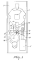
- the reference numeral 1 generally designates an electric lock with multiple-function spring.
- Each lock 1 is constituted by a fixed body 2, from which a stem 3 protrudes outward (the knob or handle for opening from the outside is connected to said stem).
- the stem 3 has, at its base, a plate 4, which can rotate on a sleeve 5, the upper edge 6 of which rests on a contrast plate 7.
- the sleeve 5 is associated with the locking element, not shown in the figure, and therefore a rotation thereof entails a corresponding retraction (or protrusion) of said locking element; the sleeve 5 is constantly associated with the internal handle.
- the plate 4, the sleeve 5 and the contrast plate 7 have respective notches 8, which are substantially shaped in a similar manner.
- a slider 9 is located below the plate 4 and the sleeve 5, can slide on a respective linear guide, and is provided with a cylindrical pin 10 that is substantially parallel to the axis of the stem 3.
- a spring 11 is constituted by a central portion 12, which forms a cylindrical winding of metal turns, and by two linear arms 13.
- the central portion 12 is fitted on the pin 10 and covers it completely, while the two arms 13 are respectively coupled within a fixed part of the body 2 and engaged on a worm screw 14, between two successive crests 15.
- the worm screw 14 is arranged laterally with respect to the slider 9 and is parallel to the linear guide of the slider 9; a first end of the worm screw rests in a fixed seat 16 of the body 2 and a second end is rigidly coupled to the shaft of an electric motor 17.
- a magnet 18 is fixed to the upper end of the slider 9 and is designed to retain a roller 19 by magnetic attraction in close contact with the slider 9.
- the motor 17 is supplied with power so that it turns the worm screw 14.
- the arm 13, arranged between two successive crests 15 of the worm screw 14, is transferred from the configuration shown in Figure 3 (arm 13 proximate to the motor 17) to the configuration shown in Figure 4 (arm 13 proximate to the fixed seat 16).
- the slider 9 is subjected to a translational motion that causes its upper end (the one that accommodates the magnet 18) to face the plate 4, the contrast plate 7, and the sleeve 5.
- the roller 19 is accommodated within the notches 8 of the plate 4, of the contrast plate 7 and of the sleeve 5, which are mutually superimposed.
- roller 19 in this position entails that said roller rigidly couples the plate 4, the contrast plate 7 and the sleeve 5 to each other: in this configuration ( Figure 4), a rotation of the outer knob (or handle), which induces a similar rotation of the stem 3, of the plate 4 and of the contrast plate 7, also rotates the sleeve 5, entailing the actuation of the locking element and therefore the opening of the lock 1.
- Access may be possible only by having an appropriately provided key, by means of which it is possible to turn the bit 20, with a consequent action of the inclined surface 21 on the lower surface of the slider 9 that entails an upward translational motion of the slider 9 (as shown in Figure 5).
- the spring 11 undergoes a deformation, reducing the angle between its two arms 13 (because the arm 13 remains engaged in the worm screw 14 proximate to the motor 17), tending to return the slider 9 downward (return translational motion prevented by the presence of the inclined surface 21).
- the upward translational motion of the slider 9 entails the engagement of the roller 19 in the notches 8 and therefore allows actuation of the locking element by means of the knob (or handle) fitted on the stem 3.
- the slider 9 By returning the bit 20 to its initial configuration, the slider 9 again performs a downward translational motion by way of the action of the spring 11, and the rotation of the stem 3 is again independent of the rotation of the sleeve 5.
Abstract
Description
Claims (13)
- An electric lock with multiple-function spring (11), of the type comprising a locking element that engages in a respective selvage of the jamb, a decoding assembly adapted to accommodate a component that bears a code, a first actuation element, which is connected to an internal handle and is directly associated with said locking element, and a second actuation element, which is connected to an external handle and is coupled to said locking element by means of an electromechanical device, characterized in that said second actuation element comprises, rigidly coupled to said external handle, a protruding stem (3) that ends with a rotating plate (4) and a contrast plate (7), which is likewise rotatable, said plates resting freely on a sleeve (5), which is likewise rotatable and is rigidly coupled to said locking element, said plate (4), said contrast plate (7) and said sleeve (5) being provided with respective notches (8), and in that said electromechanical device is constituted by an electric motor (17), on the shaft of which a worm screw (14) is fitted, and by a slider (9), which is coupled to said worm screw (14) by means of a spring (11) in which one end (13) is fixed on the body (2) of the lock (1), the central portion (12) is engaged on said slider (9), and the opposite end (13) is accommodated between two successive crests (15) of said worm screw (14), said slider (9) being provided, on its head, with a coupling means (19) that is adapted to enter said notches (8) when the slider (9) is in the forward position, in order to rigidly couple to each other said plate (4), said contrast plate (7) and said sleeve (5).
- The lock according to claim 1, characterized in that said worm screw (14) has an end that is keyed on the shaft of the motor (17), the opposite end resting in a fixed seat (16) that is rigidly coupled to the body (2) of the lock (1).
- The lock according to claim 1, characterized in that said spring (11) is provided-with two long linear arms (13) that protrude from said central portion (12) that is wound in a spiral shaped like a hollow cylinder.
- The lock according to claim 3, characterized in that said slider (9) has a pin (10) that protrudes in order to accommodate said central portion (12).
- The lock according to one or more of the preceding claims, characterized in that said slider (9) is fitted so that it can slide within a guide and can perform a translational motion from a first configuration, in which the coupling means (19) arranged on its head is entirely external to said notches (8) of the plate (4), of the contrast plate (7) and of the sleeve (5), to a second configuration, in which said means (19) is accommodated within said notches (8), rigidly coupling the plate (4), the contrast plate (7) and the sleeve (5).
- The lock according to one or more of the preceding claims, characterized in that said second configuration of said slider (9) corresponds to a position, reached by rotation of the shaft of the motor (17) and therefore of said worm screw (14), of the arm (13) of the spring (11) in which it is engaged on the worm screw (14) between the two end crests (15), the ones that are closest to said fixed seat (16) that is rigidly coupled to the body (2) of the lock (1).
- The lock according to one or more of the preceding claims, characterized in that said second configuration of said slider (9) corresponds to an arrangement of the slider (9), by way of the external mechanical action of an operator, if electric power is not available, with a consequent deformation of the spring (11) that is constituted by a reduction of the angle comprised between the two arms (13).
- The lock according to one or more of the preceding claims, characterized in that a bit (20) is arranged below the slide (9) and can move from a first configuration, in which an inclined surface (21) that protrudes from it is arranged laterally to the slider (9), to a second configuration, in which said inclined surface (21) rests on the lower surface of said slider (9), having moved it upward with said coupling means (19) within said notches (8).
- The lock according to claim 8, characterized in that said bit (20) is rotationally actuated by an operator by means of an appropriately provided key.
- The lock according to one or more of the preceding claims, characterized in that the coupling means is a roller (19) that is detachably coupled to the head of the slider (9).
- The lock according to claim 10, characterized in that said roller (19) is rigidly coupled to said head by means of an interlocking coupling.
- The lock according to claim 10 and as an alternative to claim 11, characterized in that said roller (19) is rigidly coupled on said head by means of a magnet (18).
- The lock according to one or more of the preceding claims, characterized in that the power supply of said electric motor (17) is activated following insertion of said component provided with the code in a respective receptacle of the decoding assembly.
Applications Claiming Priority (2)
| Application Number | Priority Date | Filing Date | Title |
|---|---|---|---|
| ITBO20030582 ITBO20030582A1 (en) | 2003-10-10 | 2003-10-10 | ELECTRIC LOCK PROVIDED WITH MULTIFUNCTIONAL SPRING |
| ITBO20030582 | 2003-10-10 |
Publications (3)
| Publication Number | Publication Date |
|---|---|
| EP1522659A2 true EP1522659A2 (en) | 2005-04-13 |
| EP1522659A3 EP1522659A3 (en) | 2006-12-06 |
| EP1522659B1 EP1522659B1 (en) | 2010-02-24 |
Family
ID=34308087
Family Applications (1)
| Application Number | Title | Priority Date | Filing Date |
|---|---|---|---|
| EP20040023760 Not-in-force EP1522659B1 (en) | 2003-10-10 | 2004-10-06 | Electric lock with multiple-function spring |
Country Status (7)
| Country | Link |
|---|---|
| US (1) | US7168276B2 (en) |
| EP (1) | EP1522659B1 (en) |
| CN (1) | CN1605701B (en) |
| AT (1) | ATE458888T1 (en) |
| DE (1) | DE602004025656D1 (en) |
| ES (1) | ES2339858T3 (en) |
| IT (1) | ITBO20030582A1 (en) |
Cited By (14)
| Publication number | Priority date | Publication date | Assignee | Title |
|---|---|---|---|---|
| EP1881135A1 (en) * | 2006-06-26 | 2008-01-23 | Salto Systems, S.L. | Clutch mechanism couplable to door locks with locking bolt operated by handles or knobs |
| DE102009006352A1 (en) | 2009-01-28 | 2010-08-05 | G. Schwepper Beschlag Gmbh + Co | Lock box |
| DE102009018471A1 (en) | 2009-04-22 | 2011-01-05 | G. Schwepper Beschlag Gmbh + Co | Lock box with piezomotor |
| CN101963007A (en) * | 2010-09-09 | 2011-02-02 | 苏州孔雀信天游电子有限公司 | Electric opened and closed safety mechanism of barrel-type spherical door lock |
| CN102444336A (en) * | 2011-12-07 | 2012-05-09 | 北京鼎汉技术股份有限公司 | Door lock of safety door |
| EP2466043A1 (en) * | 2010-12-20 | 2012-06-20 | Microhard S.R.L. | A coupling device of an external handle to a lock |
| EP2136019A3 (en) * | 2008-06-17 | 2013-06-19 | ASSA ABLOY Sicherheitstechnik GmbH | Sub-assembly for blocking or releasing a door lock |
| EP2754798A3 (en) * | 2013-01-11 | 2015-10-14 | ASSA ABLOY Sicherheitstechnik GmbH | Door locking device for a door with at least one door leaf |
| EP2565352A4 (en) * | 2010-04-26 | 2017-12-27 | Irevo, Inc. | Door lock drive assembly |
| DE102014103666C5 (en) | 2014-03-18 | 2019-03-14 | Günter Uhlmann | door handles |
| DE102018122016B3 (en) | 2018-09-10 | 2020-01-16 | Dom Sicherheitstechnik Gmbh & Co Kg | Coupling device for a door fitting, door fitting system and method for coupling or uncoupling a coupling device |
| EP3805489A1 (en) * | 2019-10-11 | 2021-04-14 | Henry Squire & Sons Holdings Ltd | A component for use in a locking device |
| WO2021246869A1 (en) * | 2020-06-03 | 2021-12-09 | M & C Protect B.V. | Door handle assembly |
| SE2050989A1 (en) * | 2020-08-26 | 2022-02-27 | Assa Abloy Ab | Arrangement for lock device, and lock device comprising arrangement |
Families Citing this family (19)
| Publication number | Priority date | Publication date | Assignee | Title |
|---|---|---|---|---|
| CA2650128C (en) | 2006-04-13 | 2016-11-22 | Schlage Lock Company | Electronic deadbolt lock |
| EP2017412B1 (en) * | 2007-07-18 | 2015-10-14 | iLOQ Oy | Electromechanical lock |
| TR200801927A2 (en) * | 2008-03-24 | 2009-01-21 | Vemus Endüstri̇yel Elektroni̇k Sanayi̇ Ve Ti̇caret Li̇mi̇ted Şi̇rketi̇ | Locking system with micro motor. |
| WO2010062282A1 (en) * | 2008-11-28 | 2010-06-03 | Utc Fire & Security Corporation | Semi-active electrorheological fluid clutch for electronic door lock |
| CN101696608B (en) * | 2009-10-17 | 2012-05-30 | 烟台三环科技有限公司 | Eccentric link mechanism |
| CN101705769B (en) * | 2009-11-23 | 2012-02-15 | 烟台三环科技有限公司 | Lockset |
| US8800402B2 (en) * | 2010-03-04 | 2014-08-12 | Vingcard Elsafe As | Motor mechanism |
| US8590948B2 (en) * | 2011-01-12 | 2013-11-26 | I-Tek Metal Mfg. Co., Ltd | Outer operational device for panic exit door lock |
| US9051761B2 (en) | 2011-08-02 | 2015-06-09 | Kwikset Corporation | Manually driven electronic deadbolt assembly with fixed turnpiece |
| US8904836B2 (en) * | 2012-07-18 | 2014-12-09 | Scyan Electronics LLC | Handle fixing mechanisms and methods of making and using thereof |
| US20150372488A1 (en) * | 2013-02-07 | 2015-12-24 | Nec Corporation | Electric power control system |
| WO2014151024A1 (en) | 2013-03-15 | 2014-09-25 | Kwikset Corporation | Electro-mechanical locks with bezel turning function |
| US9540847B2 (en) * | 2014-06-06 | 2017-01-10 | Rodolfo Pena | Magnetically enhanced key and lock system |
| TWI544130B (en) * | 2014-08-21 | 2016-08-01 | 台灣福興工業股份有限公司 | Handle mechanism |
| DE102015112859B3 (en) | 2015-08-05 | 2016-11-03 | Uhlmann & Zacher Gmbh | Door handle and drive carrier |
| US10738506B2 (en) | 2018-07-24 | 2020-08-11 | Schlage Lock Company Llc | Modular clutching mechanism |
| WO2020055851A1 (en) * | 2018-09-10 | 2020-03-19 | Spectrum Brands, Inc. | Locking assembly with spring mechanism |
| CN109184356A (en) * | 2018-09-19 | 2019-01-11 | 深圳市奈士迪技术研发有限公司 | A kind of safe type intelligent lock based on block chain technology |
| US20230160235A1 (en) * | 2021-11-19 | 2023-05-25 | Schlage Lock Company Llc | Lock module with mechanical override |
Citations (6)
| Publication number | Priority date | Publication date | Assignee | Title |
|---|---|---|---|---|
| WO1998028508A1 (en) * | 1996-12-24 | 1998-07-02 | Kaba Schliesssysteme Ag | Locking device |
| EP0861959A2 (en) * | 1997-02-27 | 1998-09-02 | Talleres De Escoriaza, S.A. (TESA) | Security lock with access control |
| EP1098053A2 (en) * | 1999-11-03 | 2001-05-09 | Kaba Gege GmbH | Split mandrel |
| EP1113130A1 (en) * | 1999-12-31 | 2001-07-04 | Escudos Kala Internacional S.L. | Clutch mechanism for electronic locks |
| AT6045U1 (en) * | 2002-01-30 | 2003-03-25 | Grundmann Beschlagtechnik Gmbh | DOOR LOCK WITH DIVIDED LOCKNUT |
| DE10225490A1 (en) * | 2002-03-16 | 2003-10-09 | Burg Waechter Kg | Mortise lock for door has shaft sections actively interconnected via coupling upon recognition of authorization code |
Family Cites Families (11)
| Publication number | Priority date | Publication date | Assignee | Title |
|---|---|---|---|---|
| US4820330A (en) * | 1987-07-30 | 1989-04-11 | Jeun-Kuen Lee | Structure for controlling the dead bolt used in an electronic lock |
| US5027629A (en) * | 1990-01-22 | 1991-07-02 | Liu Yin Chic | Control mechanism of electronic lock |
| US5475996A (en) * | 1994-08-29 | 1995-12-19 | Chen; Tsun-Hsing | Electromagnetic door lock |
| US6145353A (en) * | 1999-02-02 | 2000-11-14 | Unican Electronics | Electronically activated door lock assembly |
| DE19960791C1 (en) * | 1999-12-16 | 2001-04-05 | Sphinx Elektronik Gmbh | Electromechanical coupling device for door lock uses electromechanical transducer for operation of interlock between driving and driven elements |
| ES2193793B2 (en) * | 2000-03-01 | 2005-02-01 | Escudos Kala Internacional, S.L. | CONDEMNATION MECHANISM FOR ELECTRONIC LOCKS. |
| US6666053B2 (en) * | 2001-12-19 | 2003-12-23 | Randall C. Hansen | Reversible spring-loaded lock slide |
| GB2390394B (en) * | 2002-07-03 | 2004-05-26 | Shyang Feng Electric & Machine | Improved electronic lock |
| CN2565913Y (en) * | 2002-07-22 | 2003-08-13 | 祥枫工业股份有限公司 | Improved electronic lock |
| US6851291B2 (en) * | 2002-11-26 | 2005-02-08 | Sargent Manufacturing | Motorized locking mechanism |
| US7096698B2 (en) * | 2003-03-11 | 2006-08-29 | Harrow Products Llc | Override assembly for door lock systems having a clutch mechanism |
-
2003
- 2003-10-10 IT ITBO20030582 patent/ITBO20030582A1/en unknown
-
2004
- 2004-10-06 ES ES04023760T patent/ES2339858T3/en active Active
- 2004-10-06 AT AT04023760T patent/ATE458888T1/en active
- 2004-10-06 DE DE200460025656 patent/DE602004025656D1/en active Active
- 2004-10-06 EP EP20040023760 patent/EP1522659B1/en not_active Not-in-force
- 2004-10-07 US US10/959,101 patent/US7168276B2/en not_active Expired - Fee Related
- 2004-10-10 CN CN2004100855330A patent/CN1605701B/en not_active Expired - Fee Related
Patent Citations (6)
| Publication number | Priority date | Publication date | Assignee | Title |
|---|---|---|---|---|
| WO1998028508A1 (en) * | 1996-12-24 | 1998-07-02 | Kaba Schliesssysteme Ag | Locking device |
| EP0861959A2 (en) * | 1997-02-27 | 1998-09-02 | Talleres De Escoriaza, S.A. (TESA) | Security lock with access control |
| EP1098053A2 (en) * | 1999-11-03 | 2001-05-09 | Kaba Gege GmbH | Split mandrel |
| EP1113130A1 (en) * | 1999-12-31 | 2001-07-04 | Escudos Kala Internacional S.L. | Clutch mechanism for electronic locks |
| AT6045U1 (en) * | 2002-01-30 | 2003-03-25 | Grundmann Beschlagtechnik Gmbh | DOOR LOCK WITH DIVIDED LOCKNUT |
| DE10225490A1 (en) * | 2002-03-16 | 2003-10-09 | Burg Waechter Kg | Mortise lock for door has shaft sections actively interconnected via coupling upon recognition of authorization code |
Cited By (23)
| Publication number | Priority date | Publication date | Assignee | Title |
|---|---|---|---|---|
| ES2323201A1 (en) * | 2006-06-26 | 2009-07-08 | Salto Systems S.L. | Clutch mechanism couplable to door locks with locking bolt operated by handles or knobs |
| EP1881135A1 (en) * | 2006-06-26 | 2008-01-23 | Salto Systems, S.L. | Clutch mechanism couplable to door locks with locking bolt operated by handles or knobs |
| EP2136019A3 (en) * | 2008-06-17 | 2013-06-19 | ASSA ABLOY Sicherheitstechnik GmbH | Sub-assembly for blocking or releasing a door lock |
| DE102009006352A1 (en) | 2009-01-28 | 2010-08-05 | G. Schwepper Beschlag Gmbh + Co | Lock box |
| DE102009006352B4 (en) * | 2009-01-28 | 2011-02-17 | G. Schwepper Beschlag Gmbh + Co | Lock box |
| DE102009018471A1 (en) | 2009-04-22 | 2011-01-05 | G. Schwepper Beschlag Gmbh + Co | Lock box with piezomotor |
| DE102009018471B4 (en) * | 2009-04-22 | 2021-02-04 | SÜD-Metall Schließsysteme Leipzig GmbH | Lock box with piezo motor |
| EP2565352A4 (en) * | 2010-04-26 | 2017-12-27 | Irevo, Inc. | Door lock drive assembly |
| CN101963007A (en) * | 2010-09-09 | 2011-02-02 | 苏州孔雀信天游电子有限公司 | Electric opened and closed safety mechanism of barrel-type spherical door lock |
| EP2466043A1 (en) * | 2010-12-20 | 2012-06-20 | Microhard S.R.L. | A coupling device of an external handle to a lock |
| ITMI20102326A1 (en) * | 2010-12-20 | 2012-06-21 | Microhard Srl | PAIR OF THE EXTERNAL HANDLE WITH A LOCK |
| CN102444336B (en) * | 2011-12-07 | 2013-08-21 | 北京鼎汉技术股份有限公司 | Door lock of safety door |
| CN102444336A (en) * | 2011-12-07 | 2012-05-09 | 北京鼎汉技术股份有限公司 | Door lock of safety door |
| EP2754798A3 (en) * | 2013-01-11 | 2015-10-14 | ASSA ABLOY Sicherheitstechnik GmbH | Door locking device for a door with at least one door leaf |
| DE102014103666C5 (en) | 2014-03-18 | 2019-03-14 | Günter Uhlmann | door handles |
| DE102014103666C9 (en) | 2014-03-18 | 2019-06-06 | Günter Uhlmann | door handles |
| DE102018122016B3 (en) | 2018-09-10 | 2020-01-16 | Dom Sicherheitstechnik Gmbh & Co Kg | Coupling device for a door fitting, door fitting system and method for coupling or uncoupling a coupling device |
| EP3620598A1 (en) | 2018-09-10 | 2020-03-11 | DOM-Sicherheitstechnik GmbH & Co. KG | Coupling device for a door fitting, door fitting system and method for coupling or uncoupling of a coupling device |
| EP3805489A1 (en) * | 2019-10-11 | 2021-04-14 | Henry Squire & Sons Holdings Ltd | A component for use in a locking device |
| WO2021246869A1 (en) * | 2020-06-03 | 2021-12-09 | M & C Protect B.V. | Door handle assembly |
| NL2025736B1 (en) * | 2020-06-03 | 2022-01-26 | M & C Protect B V | door handle assembly |
| SE2050989A1 (en) * | 2020-08-26 | 2022-02-27 | Assa Abloy Ab | Arrangement for lock device, and lock device comprising arrangement |
| SE544835C2 (en) * | 2020-08-26 | 2022-12-06 | Assa Abloy Ab | Arrangement for lock device, and lock device comprising arrangement |
Also Published As
| Publication number | Publication date |
|---|---|
| DE602004025656D1 (en) | 2010-04-08 |
| EP1522659B1 (en) | 2010-02-24 |
| US7168276B2 (en) | 2007-01-30 |
| CN1605701A (en) | 2005-04-13 |
| ATE458888T1 (en) | 2010-03-15 |
| EP1522659A3 (en) | 2006-12-06 |
| US20050086984A1 (en) | 2005-04-28 |
| CN1605701B (en) | 2010-12-08 |
| ES2339858T3 (en) | 2010-05-26 |
| ITBO20030582A1 (en) | 2005-04-11 |
Similar Documents
| Publication | Publication Date | Title |
|---|---|---|
| EP1522659A2 (en) | Electric lock with multiple-function spring | |
| EP1522658B1 (en) | Electric lock with magnetic support of the coupling element | |
| US5421178A (en) | Motorized lock actuator for cylindrical lockset | |
| US7874190B2 (en) | Electromechanical lock cylinder | |
| RU2337220C2 (en) | Cylinder door lock | |
| US5953942A (en) | Catch mechanism for locks | |
| US8516863B2 (en) | High security lock | |
| US8978428B2 (en) | Apparatus for automatically returning a lock to a desired orientation | |
| PL190093B1 (en) | Closing device | |
| US5931430A (en) | Motor assembly for cylindrical lockset | |
| ES2926957T3 (en) | Actuating element for a box lock | |
| KR20010072604A (en) | Electrically controlled lock | |
| WO1998015703A1 (en) | Electro-mechanical lock | |
| PT1842989E (en) | Mortise lock | |
| US5865483A (en) | Electromechanical locking system | |
| WO2004072418A1 (en) | Padlock with solenoid | |
| EP1526235B1 (en) | Lock having a lockable handle shaft | |
| US3336775A (en) | Door lock visual indicator pin | |
| CZ294473B6 (en) | Cylinder-type lock | |
| US11982104B2 (en) | Lock cylinder | |
| JP2010106547A (en) | Lock breakage preventing device for handle lock | |
| US20210388637A1 (en) | Lock cylinder | |
| RU2015278C1 (en) | Door lock | |
| JP2001032590A5 (en) | ||
| ES2263380B1 (en) | MECHANISM OF ELECTROMECHANICAL DRIVING FOR A LOCK. |
Legal Events
| Date | Code | Title | Description |
|---|---|---|---|
| PUAI | Public reference made under article 153(3) epc to a published international application that has entered the european phase |
Free format text: ORIGINAL CODE: 0009012 |
|
| AK | Designated contracting states |
Kind code of ref document: A2 Designated state(s): AT BE BG CH CY CZ DE DK EE ES FI FR GB GR HU IE IT LI LU MC NL PL PT RO SE SI SK TR |
|
| AX | Request for extension of the european patent |
Extension state: AL HR LT LV MK |
|
| RAP1 | Party data changed (applicant data changed or rights of an application transferred) |
Owner name: CISA S.P.A. |
|
| PUAL | Search report despatched |
Free format text: ORIGINAL CODE: 0009013 |
|
| AK | Designated contracting states |
Kind code of ref document: A3 Designated state(s): AT BE BG CH CY CZ DE DK EE ES FI FR GB GR HU IE IT LI LU MC NL PL PT RO SE SI SK TR |
|
| AX | Request for extension of the european patent |
Extension state: AL HR LT LV MK |
|
| 17P | Request for examination filed |
Effective date: 20070521 |
|
| AKX | Designation fees paid |
Designated state(s): AT BE BG CH CY CZ DE DK EE ES FI FR GB GR HU IE IT LI LU MC NL PL PT RO SE SI SK TR |
|
| 17Q | First examination report despatched |
Effective date: 20080606 |
|
| GRAP | Despatch of communication of intention to grant a patent |
Free format text: ORIGINAL CODE: EPIDOSNIGR1 |
|
| GRAS | Grant fee paid |
Free format text: ORIGINAL CODE: EPIDOSNIGR3 |
|
| GRAA | (expected) grant |
Free format text: ORIGINAL CODE: 0009210 |
|
| AK | Designated contracting states |
Kind code of ref document: B1 Designated state(s): AT BE BG CH CY CZ DE DK EE ES FI FR GB GR HU IE IT LI LU MC NL PL PT RO SE SI SK TR |
|
| REG | Reference to a national code |
Ref country code: GB Ref legal event code: FG4D |
|
| REG | Reference to a national code |
Ref country code: CH Ref legal event code: EP |
|
| REG | Reference to a national code |
Ref country code: IE Ref legal event code: FG4D |
|
| REF | Corresponds to: |
Ref document number: 602004025656 Country of ref document: DE Date of ref document: 20100408 Kind code of ref document: P |
|
| REG | Reference to a national code |
Ref country code: NL Ref legal event code: T3 |
|
| REG | Reference to a national code |
Ref country code: GR Ref legal event code: EP Ref document number: 20100400912 Country of ref document: GR |
|
| REG | Reference to a national code |
Ref country code: ES Ref legal event code: FG2A Ref document number: 2339858 Country of ref document: ES Kind code of ref document: T3 |
|
| PG25 | Lapsed in a contracting state [announced via postgrant information from national office to epo] |
Ref country code: PT Free format text: LAPSE BECAUSE OF FAILURE TO SUBMIT A TRANSLATION OF THE DESCRIPTION OR TO PAY THE FEE WITHIN THE PRESCRIBED TIME-LIMIT Effective date: 20100625 |
|
| PG25 | Lapsed in a contracting state [announced via postgrant information from national office to epo] |
Ref country code: PL Free format text: LAPSE BECAUSE OF FAILURE TO SUBMIT A TRANSLATION OF THE DESCRIPTION OR TO PAY THE FEE WITHIN THE PRESCRIBED TIME-LIMIT Effective date: 20100224 Ref country code: FI Free format text: LAPSE BECAUSE OF FAILURE TO SUBMIT A TRANSLATION OF THE DESCRIPTION OR TO PAY THE FEE WITHIN THE PRESCRIBED TIME-LIMIT Effective date: 20100224 Ref country code: SI Free format text: LAPSE BECAUSE OF FAILURE TO SUBMIT A TRANSLATION OF THE DESCRIPTION OR TO PAY THE FEE WITHIN THE PRESCRIBED TIME-LIMIT Effective date: 20100224 |
|
| PG25 | Lapsed in a contracting state [announced via postgrant information from national office to epo] |
Ref country code: CY Free format text: LAPSE BECAUSE OF FAILURE TO SUBMIT A TRANSLATION OF THE DESCRIPTION OR TO PAY THE FEE WITHIN THE PRESCRIBED TIME-LIMIT Effective date: 20100224 Ref country code: EE Free format text: LAPSE BECAUSE OF FAILURE TO SUBMIT A TRANSLATION OF THE DESCRIPTION OR TO PAY THE FEE WITHIN THE PRESCRIBED TIME-LIMIT Effective date: 20100224 Ref country code: RO Free format text: LAPSE BECAUSE OF FAILURE TO SUBMIT A TRANSLATION OF THE DESCRIPTION OR TO PAY THE FEE WITHIN THE PRESCRIBED TIME-LIMIT Effective date: 20100224 Ref country code: SE Free format text: LAPSE BECAUSE OF FAILURE TO SUBMIT A TRANSLATION OF THE DESCRIPTION OR TO PAY THE FEE WITHIN THE PRESCRIBED TIME-LIMIT Effective date: 20100224 |
|
| PG25 | Lapsed in a contracting state [announced via postgrant information from national office to epo] |
Ref country code: CZ Free format text: LAPSE BECAUSE OF FAILURE TO SUBMIT A TRANSLATION OF THE DESCRIPTION OR TO PAY THE FEE WITHIN THE PRESCRIBED TIME-LIMIT Effective date: 20100224 Ref country code: BG Free format text: LAPSE BECAUSE OF FAILURE TO SUBMIT A TRANSLATION OF THE DESCRIPTION OR TO PAY THE FEE WITHIN THE PRESCRIBED TIME-LIMIT Effective date: 20100524 Ref country code: SK Free format text: LAPSE BECAUSE OF FAILURE TO SUBMIT A TRANSLATION OF THE DESCRIPTION OR TO PAY THE FEE WITHIN THE PRESCRIBED TIME-LIMIT Effective date: 20100224 |
|
| PLBE | No opposition filed within time limit |
Free format text: ORIGINAL CODE: 0009261 |
|
| STAA | Information on the status of an ep patent application or granted ep patent |
Free format text: STATUS: NO OPPOSITION FILED WITHIN TIME LIMIT |
|
| PG25 | Lapsed in a contracting state [announced via postgrant information from national office to epo] |
Ref country code: DK Free format text: LAPSE BECAUSE OF FAILURE TO SUBMIT A TRANSLATION OF THE DESCRIPTION OR TO PAY THE FEE WITHIN THE PRESCRIBED TIME-LIMIT Effective date: 20100224 |
|
| PGFP | Annual fee paid to national office [announced via postgrant information from national office to epo] |
Ref country code: NL Payment date: 20101028 Year of fee payment: 7 |
|
| 26N | No opposition filed |
Effective date: 20101125 |
|
| PG25 | Lapsed in a contracting state [announced via postgrant information from national office to epo] |
Ref country code: MC Free format text: LAPSE BECAUSE OF NON-PAYMENT OF DUE FEES Effective date: 20101031 |
|
| REG | Reference to a national code |
Ref country code: CH Ref legal event code: PL |
|
| PG25 | Lapsed in a contracting state [announced via postgrant information from national office to epo] |
Ref country code: CH Free format text: LAPSE BECAUSE OF NON-PAYMENT OF DUE FEES Effective date: 20101031 Ref country code: LI Free format text: LAPSE BECAUSE OF NON-PAYMENT OF DUE FEES Effective date: 20101031 |
|
| PG25 | Lapsed in a contracting state [announced via postgrant information from national office to epo] |
Ref country code: IE Free format text: LAPSE BECAUSE OF NON-PAYMENT OF DUE FEES Effective date: 20101006 |
|
| REG | Reference to a national code |
Ref country code: NL Ref legal event code: V1 Effective date: 20120501 |
|
| PG25 | Lapsed in a contracting state [announced via postgrant information from national office to epo] |
Ref country code: NL Free format text: LAPSE BECAUSE OF NON-PAYMENT OF DUE FEES Effective date: 20120501 |
|
| PG25 | Lapsed in a contracting state [announced via postgrant information from national office to epo] |
Ref country code: LU Free format text: LAPSE BECAUSE OF NON-PAYMENT OF DUE FEES Effective date: 20101006 Ref country code: HU Free format text: LAPSE BECAUSE OF FAILURE TO SUBMIT A TRANSLATION OF THE DESCRIPTION OR TO PAY THE FEE WITHIN THE PRESCRIBED TIME-LIMIT Effective date: 20100825 |
|
| PGFP | Annual fee paid to national office [announced via postgrant information from national office to epo] |
Ref country code: TR Payment date: 20120918 Year of fee payment: 9 |
|
| PGFP | Annual fee paid to national office [announced via postgrant information from national office to epo] |
Ref country code: BE Payment date: 20120926 Year of fee payment: 9 Ref country code: DE Payment date: 20121019 Year of fee payment: 9 |
|
| PGFP | Annual fee paid to national office [announced via postgrant information from national office to epo] |
Ref country code: AT Payment date: 20121030 Year of fee payment: 9 |
|
| PGFP | Annual fee paid to national office [announced via postgrant information from national office to epo] |
Ref country code: GB Payment date: 20130930 Year of fee payment: 10 |
|
| PGFP | Annual fee paid to national office [announced via postgrant information from national office to epo] |
Ref country code: GR Payment date: 20131030 Year of fee payment: 10 |
|
| BERE | Be: lapsed |
Owner name: CISA S.P.A. Effective date: 20131031 |
|
| REG | Reference to a national code |
Ref country code: AT Ref legal event code: MM01 Ref document number: 458888 Country of ref document: AT Kind code of ref document: T Effective date: 20131006 |
|
| REG | Reference to a national code |
Ref country code: DE Ref legal event code: R119 Ref document number: 602004025656 Country of ref document: DE Effective date: 20140501 |
|
| PG25 | Lapsed in a contracting state [announced via postgrant information from national office to epo] |
Ref country code: DE Free format text: LAPSE BECAUSE OF NON-PAYMENT OF DUE FEES Effective date: 20140501 Ref country code: AT Free format text: LAPSE BECAUSE OF NON-PAYMENT OF DUE FEES Effective date: 20131006 |
|
| PG25 | Lapsed in a contracting state [announced via postgrant information from national office to epo] |
Ref country code: BE Free format text: LAPSE BECAUSE OF NON-PAYMENT OF DUE FEES Effective date: 20131031 |
|
| GBPC | Gb: european patent ceased through non-payment of renewal fee |
Effective date: 20141006 |
|
| REG | Reference to a national code |
Ref country code: GR Ref legal event code: ML Ref document number: 20100400912 Country of ref document: GR Effective date: 20150505 |
|
| PG25 | Lapsed in a contracting state [announced via postgrant information from national office to epo] |
Ref country code: GB Free format text: LAPSE BECAUSE OF NON-PAYMENT OF DUE FEES Effective date: 20141006 |
|
| PG25 | Lapsed in a contracting state [announced via postgrant information from national office to epo] |
Ref country code: GR Free format text: LAPSE BECAUSE OF NON-PAYMENT OF DUE FEES Effective date: 20150505 |
|
| PG25 | Lapsed in a contracting state [announced via postgrant information from national office to epo] |
Ref country code: TR Free format text: LAPSE BECAUSE OF NON-PAYMENT OF DUE FEES Effective date: 20131006 |
|
| REG | Reference to a national code |
Ref country code: FR Ref legal event code: PLFP Year of fee payment: 12 |
|
| REG | Reference to a national code |
Ref country code: FR Ref legal event code: PLFP Year of fee payment: 13 |
|
| PGFP | Annual fee paid to national office [announced via postgrant information from national office to epo] |
Ref country code: ES Payment date: 20161026 Year of fee payment: 13 |
|
| REG | Reference to a national code |
Ref country code: FR Ref legal event code: PLFP Year of fee payment: 14 |
|
| PGFP | Annual fee paid to national office [announced via postgrant information from national office to epo] |
Ref country code: FR Payment date: 20171013 Year of fee payment: 14 |
|
| PGFP | Annual fee paid to national office [announced via postgrant information from national office to epo] |
Ref country code: IT Payment date: 20171024 Year of fee payment: 14 |
|
| REG | Reference to a national code |
Ref country code: ES Ref legal event code: FD2A Effective date: 20181220 |
|
| PG25 | Lapsed in a contracting state [announced via postgrant information from national office to epo] |
Ref country code: ES Free format text: LAPSE BECAUSE OF NON-PAYMENT OF DUE FEES Effective date: 20171007 |
|
| PG25 | Lapsed in a contracting state [announced via postgrant information from national office to epo] |
Ref country code: FR Free format text: LAPSE BECAUSE OF NON-PAYMENT OF DUE FEES Effective date: 20181031 |
|
| PG25 | Lapsed in a contracting state [announced via postgrant information from national office to epo] |
Ref country code: IT Free format text: LAPSE BECAUSE OF NON-PAYMENT OF DUE FEES Effective date: 20181006 |