EP1522432A1 - Suspension - Google Patents
Suspension Download PDFInfo
- Publication number
- EP1522432A1 EP1522432A1 EP04022418A EP04022418A EP1522432A1 EP 1522432 A1 EP1522432 A1 EP 1522432A1 EP 04022418 A EP04022418 A EP 04022418A EP 04022418 A EP04022418 A EP 04022418A EP 1522432 A1 EP1522432 A1 EP 1522432A1
- Authority
- EP
- European Patent Office
- Prior art keywords
- wheel
- lower arm
- stabilizer bar
- suspension
- arm
- Prior art date
- Legal status (The legal status is an assumption and is not a legal conclusion. Google has not performed a legal analysis and makes no representation as to the accuracy of the status listed.)
- Granted
Links
- 239000000725 suspension Substances 0.000 title claims abstract description 58
- 239000003381 stabilizer Substances 0.000 claims abstract description 83
- 239000006096 absorbing agent Substances 0.000 claims description 9
- 230000035939 shock Effects 0.000 claims description 9
- 238000005096 rolling process Methods 0.000 claims description 4
- 239000002184 metal Substances 0.000 description 14
- 229910052751 metal Inorganic materials 0.000 description 14
- 230000007935 neutral effect Effects 0.000 description 9
- 230000000694 effects Effects 0.000 description 3
- 238000005242 forging Methods 0.000 description 2
- 230000003247 decreasing effect Effects 0.000 description 1
- 239000000463 material Substances 0.000 description 1
- 150000002739 metals Chemical class 0.000 description 1
Images


Classifications
-
- B—PERFORMING OPERATIONS; TRANSPORTING
- B60—VEHICLES IN GENERAL
- B60G—VEHICLE SUSPENSION ARRANGEMENTS
- B60G21/00—Interconnection systems for two or more resiliently-suspended wheels, e.g. for stabilising a vehicle body with respect to acceleration, deceleration or centrifugal forces
- B60G21/02—Interconnection systems for two or more resiliently-suspended wheels, e.g. for stabilising a vehicle body with respect to acceleration, deceleration or centrifugal forces permanently interconnected
- B60G21/04—Interconnection systems for two or more resiliently-suspended wheels, e.g. for stabilising a vehicle body with respect to acceleration, deceleration or centrifugal forces permanently interconnected mechanically
- B60G21/05—Interconnection systems for two or more resiliently-suspended wheels, e.g. for stabilising a vehicle body with respect to acceleration, deceleration or centrifugal forces permanently interconnected mechanically between wheels on the same axle but on different sides of the vehicle, i.e. the left and right wheel suspensions being interconnected
- B60G21/055—Stabiliser bars
- B60G21/0551—Mounting means therefor
-
- B—PERFORMING OPERATIONS; TRANSPORTING
- B60—VEHICLES IN GENERAL
- B60G—VEHICLE SUSPENSION ARRANGEMENTS
- B60G3/00—Resilient suspensions for a single wheel
- B60G3/02—Resilient suspensions for a single wheel with a single pivoted arm
- B60G3/04—Resilient suspensions for a single wheel with a single pivoted arm the arm being essentially transverse to the longitudinal axis of the vehicle
- B60G3/06—Resilient suspensions for a single wheel with a single pivoted arm the arm being essentially transverse to the longitudinal axis of the vehicle the arm being rigid
-
- B—PERFORMING OPERATIONS; TRANSPORTING
- B60—VEHICLES IN GENERAL
- B60G—VEHICLE SUSPENSION ARRANGEMENTS
- B60G7/00—Pivoted suspension arms; Accessories thereof
- B60G7/001—Suspension arms, e.g. constructional features
-
- B—PERFORMING OPERATIONS; TRANSPORTING
- B60—VEHICLES IN GENERAL
- B60G—VEHICLE SUSPENSION ARRANGEMENTS
- B60G2200/00—Indexing codes relating to suspension types
- B60G2200/10—Independent suspensions
- B60G2200/14—Independent suspensions with lateral arms
- B60G2200/142—Independent suspensions with lateral arms with a single lateral arm, e.g. MacPherson type
-
- B—PERFORMING OPERATIONS; TRANSPORTING
- B60—VEHICLES IN GENERAL
- B60G—VEHICLE SUSPENSION ARRANGEMENTS
- B60G2200/00—Indexing codes relating to suspension types
- B60G2200/40—Indexing codes relating to the wheels in the suspensions
- B60G2200/44—Indexing codes relating to the wheels in the suspensions steerable
-
- B—PERFORMING OPERATIONS; TRANSPORTING
- B60—VEHICLES IN GENERAL
- B60G—VEHICLE SUSPENSION ARRANGEMENTS
- B60G2202/00—Indexing codes relating to the type of spring, damper or actuator
- B60G2202/10—Type of spring
- B60G2202/13—Torsion spring
- B60G2202/135—Stabiliser bar and/or tube
-
- B—PERFORMING OPERATIONS; TRANSPORTING
- B60—VEHICLES IN GENERAL
- B60G—VEHICLE SUSPENSION ARRANGEMENTS
- B60G2204/00—Indexing codes related to suspensions per se or to auxiliary parts
- B60G2204/10—Mounting of suspension elements
- B60G2204/12—Mounting of springs or dampers
- B60G2204/122—Mounting of torsion springs
- B60G2204/1222—Middle mounts of stabiliser on vehicle body or chassis
-
- B—PERFORMING OPERATIONS; TRANSPORTING
- B60—VEHICLES IN GENERAL
- B60G—VEHICLE SUSPENSION ARRANGEMENTS
- B60G2204/00—Indexing codes related to suspensions per se or to auxiliary parts
- B60G2204/10—Mounting of suspension elements
- B60G2204/12—Mounting of springs or dampers
- B60G2204/122—Mounting of torsion springs
- B60G2204/1224—End mounts of stabiliser on wheel suspension
-
- B—PERFORMING OPERATIONS; TRANSPORTING
- B60—VEHICLES IN GENERAL
- B60G—VEHICLE SUSPENSION ARRANGEMENTS
- B60G2204/00—Indexing codes related to suspensions per se or to auxiliary parts
- B60G2204/10—Mounting of suspension elements
- B60G2204/15—Mounting of subframes
-
- B—PERFORMING OPERATIONS; TRANSPORTING
- B60—VEHICLES IN GENERAL
- B60G—VEHICLE SUSPENSION ARRANGEMENTS
- B60G2206/00—Indexing codes related to the manufacturing of suspensions: constructional features, the materials used, procedures or tools
- B60G2206/01—Constructional features of suspension elements, e.g. arms, dampers, springs
- B60G2206/10—Constructional features of arms
- B60G2206/122—Constructional features of arms the arm having L-shape
-
- B—PERFORMING OPERATIONS; TRANSPORTING
- B60—VEHICLES IN GENERAL
- B60G—VEHICLE SUSPENSION ARRANGEMENTS
- B60G2206/00—Indexing codes related to the manufacturing of suspensions: constructional features, the materials used, procedures or tools
- B60G2206/01—Constructional features of suspension elements, e.g. arms, dampers, springs
- B60G2206/10—Constructional features of arms
- B60G2206/16—Constructional features of arms the arm having a U profile and/or made of a plate
-
- B—PERFORMING OPERATIONS; TRANSPORTING
- B60—VEHICLES IN GENERAL
- B60G—VEHICLE SUSPENSION ARRANGEMENTS
- B60G2206/00—Indexing codes related to the manufacturing of suspensions: constructional features, the materials used, procedures or tools
- B60G2206/01—Constructional features of suspension elements, e.g. arms, dampers, springs
- B60G2206/40—Constructional features of dampers and/or springs
- B60G2206/42—Springs
- B60G2206/427—Stabiliser bars or tubes
-
- B—PERFORMING OPERATIONS; TRANSPORTING
- B60—VEHICLES IN GENERAL
- B60G—VEHICLE SUSPENSION ARRANGEMENTS
- B60G2206/00—Indexing codes related to the manufacturing of suspensions: constructional features, the materials used, procedures or tools
- B60G2206/01—Constructional features of suspension elements, e.g. arms, dampers, springs
- B60G2206/60—Subframe construction
Definitions
- the present invention relates to a suspension including a stabilizer bar and two lower arms.
- Japanese Patent Application Publication No. 2001-171326 discloses a suspension including a stabilizer bar and a lower arm, wherein a space is provided between the lower arm and a portion of a body-side member, and the lower arm and the stabilizer bar are attached such that a portion of the stabilizer bar is accommodated by the space.
- Japanese Patent Application Publications Nos. 8-318722 and 9-123722 each. disclose a lower arm having a recess opening upward.
- a suspension for use with a vehicle having a first pair of front left wheel and front right wheel and a second pair of rear left wheel and rear right wheel, the suspension including a left lower arm and a right lower arm corresponding to the left wheel and the right wheel of at least one pair of the first and second pairs, respectively; and a stabilizer bar which is provided between the left wheel and the right wheel, the left lower arm, the right lower arm, and the stabilizer bar being provided such that at least when the suspension fully rebounds, at least a portion of a first cross section of each of opposite wheel-side portions of the stabilizer bar that are located on respective sides of the left wheel and the right wheel is positioned below a straight line connecting between respective upper ends of two portions of a second cross section of a corresponding one of the left lower arm and the right lower arm, the first and second cross sections being taken along a plane perpendicular to an axis line of the each wheel-side portion of the stabilizer bar, the two portions of the second cross section being located on either side of
- the stabilizer bar has, in its plan view, a generally U-shaped configuration, and is provided between a right wheel and a left wheel of a vehicle.
- the stabilizer bar includes an intermediate portion extending in a direction substantially parallel to a widthwise direction of the vehicle, and a left arm (or wheel-side) portion and a right arm (or wheel-side) portion which are located on either side of the intermediate portion and each of which extends in a direction having a component parallel to a lengthwise direction of the vehicle. Therefore, an axis line of the stabilizer bar extends, in the intermediate portion of the bar, in the direction substantially parallel to the widthwise direction of the vehicle, and extends, in each of the left and right arm portions of the bar, in the direction having the component parallel to the lengthwise direction of the vehicle.
- Respective free ends of the left and right arm portions of the stabilizer bar are supported by two wheel-side members, such as the two lower arms, or two shock absorbers, that are related to the left and right wheels of the vehicle, respectively, such that the left and right arm portions are pivotable or swingable, but are not upwardly or downwardly movable, relative to the two wheel-side members, respectively.
- the intermediate portion of the stabilizer bar is supported by a body-side member such that the intermediate portion is not upwardly or downwardly movable relative to the body-side member.
- the left and right arm portions of the stabilizer bar extend above the two lower arms, respectively.
- the stabilizer bar may be provided such that when an arbitrary one of the two wheel-side members fully rebounds relative to the body-side member, a portion of the first cross section of the stabilizer bar is positioned below the straight line passing through the respective upper ends of the two side portions of the second cross section of a corresponding one of the two lower arms that are located on either side of the bar, or such that when the arbitrary wheel-side member fully rebounds relative to the body-side member, an entirety of the first cross section of the stabilizer bar is positioned below the straight line.
- the stabilizer bar may be provided such that not only when an arbitrary one of the two wheel-side members fully rebounds, but also when the arbitrary wheel-side member is in a normal or neutral state, a portion of the first cross section of the stabilizer bar is positioned below the straight line.
- the normal or neutral state means, e.g., a state in which the arbitrary wheel-side member takes a reference height position relative to the body-side member, or a state in which the vehicle carries a standard load and is stopped, or is straightly running, on a horizontal road surface.
- the stabilizer bar is provided such that even when the arbitrary wheel-side member fully rebounds, the stabilizer bar is not interfered with by the corresponding lower arm.
- the twisting of the stabilizer bar that is caused by the rolling of the vehicle is not limited by the lower arms.
- the lower arms may be either of so-called “A” type or of so-called “L” type.
- Each lower arm has a generally flat shape, and may be produced by press working of a metal sheet.
- the suspension may be of strut type (i.e., Mcfarson strut type) or of double Wishborn type.
- the suspension in accordance with the present invention can be provided in a reduced space, without lowering a rolling-restraining effect of the stabilizer bar thereof.
- each of the left lower arm and the right lower arm has a recess opening upward, and at least when the suspension fully rebounds, at least the portion of the first cross section of the each wheel-side portion of the stabilizer bar is positioned in the recess of the corresponding one lower arm.
- each of the left lower arm and the right lower arm has a through-hole formed through a thickness thereof and opening upward and downward, and at least when the suspension fully rebounds, at least the portion of the first cross section of the each wheel-side portion of the stabilizer bar is positioned in the through-hole of the corresponding one lower arm.
- Each of the two lower arms may have a recess or a through-hole that is formed to have a required strength or a decreased weight.
- the recess or the through-hole may be utilized to accommodate a portion of the stabilizer bar.
- each lower arm may have a recess or a through-hole that is exclusively used to accommodate a portion of the stabilizer bar.
- each lower arm has the recess or the through-hole, in at least a portion thereof specified by a positional relationship between the each lower arm and the stabilizer bar.
- the term "recess” means a vacant space which opens upward but does not open downward, that is, does not extend through a thickness of each lower arm but has a bottom wall constituted by the material of the each lower arm.
- the metal sheet may be inwardly curved, as shown in Fig. 5, so that the recess of the lower arm is defined by an outer surface of the lower arm, or alternatively the metal sheet may be outwardly curved, as shown in Fig. 7, so that the recess of the lower arm is defined by an inner surface of the lower arm.
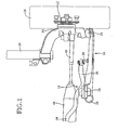
- the present suspension is a Mcfarson strut type suspension.
- two steering wheels 10 (only one steering wheel 10 is shown in the figures) as two front wheels out of four wheels of the vehicle are fixed, with bolts, to two axle hubs 12 (only one axle hub 12 is shown in the figures), respectively, and two steering knuckles 14 (only one steering knuckle 14 is shown in the figures) are attached to the two axle hubs 12, respectively, such that the steering knuckles 14 are rotatable relative to the corresponding axle hubs 12.
- the present suspension includes two lower arms 16 (only one lower arm 16 is shown in the figures), a stabilizer bar 18, and two shock absorbers 20 (only one shock absorber 20 is shown in the figures).
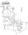
- Each lower arm 16 is of so-called “L” type, and is produced by press working of a sheet metal. This lower arm 16 is lighter than a lower arm produced by forging.
- Each lower arm 16 is attached, at one of opposite end portions thereof, to a lower end portion of the corresponding steering knuckle 14 via a ball joint 24, such that the lower arm 16 is rollable relative to the steering knuckle 14.
- the other end portion of the lower arm 16 includes two connection portions 26, 28 each of which includes a rubber bushing and is connected to a body-side member 30, shown in Fig. 2, such that the lower arm 16 is pivotable relative to the body-side member 30. As shown in Figs.
- the lower arm 16 has a recess 32 that opens in an upper surface thereof and is located in a central portion thereof.
- the recess 32 extends over a generally entire area of the upper surface of the lower arm 16. As shown in Fig. 5, the recess 32 opens upward, and a shear center of the lower arm 16 is located in the vicinity of a plane passing through an upper end of the recess 32.
- the recess 32 of the lower arm 16 is formed by deforming the metal sheet such that a central portion of the metal sheet is inwardly curved. Thus, an outer surface Sout of the sheet metal defines the recess 32.
- the stabilizer bar 18 has, in its plan view, a generally U-shaped configuration, and is provided between the left and right steering wheels 10 of the vehicle.
- the stabilizer bar 18 includes an intermediate portion 34 extending generally parallel to a widthwise direction of the vehicle, and a left and a right arm (or wheel-side) portion 36 (only one arm portion 36 is shown in the figures) which are provided on either side of the intermediate portion 34 and extend generally parallel to a lengthwise direction of the vehicle. As shown in Fig.
- an axis line, Ls, of the stabilizer bar 18 extends such that in the intermediate portion 34 of the bar 18, the axis line Ls extends generally parallel to the widthwise direction of the vehicle and, in each of the two arm portions 36 of the bar 18, the axis line Ls extends in a direction having a component parallel to the lengthwise direction of the vehicle.
- a free end portion of each of the two arm portions 36 of the stabilizer bar 18 is attached via a corresponding one of two connection portions 38 (only one connection portion 38 is shown) to a corresponding one of the two lower arms 16, such that the each arm portion 36 or the bar 18 is pivotable relative to the one lower arm 16, and is not movable in an upward or downward direction relative to the same 16.
- the intermediate portion 34 of the stabilizer bar 18 is supported by the body-side member 30 via two support portions 40 (only one support portion 40 is shown) each of which includes a rubber bushing, such that the intermediate portion 34 or the bar 18 is not movable in the upward or downward direction relative to the body-side member 30.
- Each of the two arm portions 36 extends above a corresponding one of the two lower arms 16.
- the two shock absorbers 20 are attached to respective upper end portions of the two steering knuckles 14. Each shock absorber 20 is provided between the corresponding steering knuckle 14 and another body-side member, not shown, of the vehicle, and functions as a link member.
- Two knuckle arms 15 (only one knuckle arm 15 is shown) are supported by the two steering knuckles 14, respectively, and two tie rods 46 (only one tie rod 46 is shown in the figures) are connected to the two knuckle arms 15, respectively. When the tie rods 46 are moved in the widthwise direction of the vehicle, the left and right steering wheels 10 are steered.
- the stabilizer bar 18 extends below the tie rods 46. It is preferred that the tie rods 46 be located in the vicinity of the corresponding lower arms 16, in view of adjustment of a toe angle of each steering wheel 10. Meanwhile, the two connection portions 38 with which the stabilizer bar 18 is connected to the two lower arms 16, are located at respective positions nearer to a front end of the vehicle than respective positions where the two tie rods 46 are connected to the corresponding knuckle arms 15, and the two arm portions 36 of the bar 18 extend from the two connection portions 38, respectively, toward a rear end of the vehicle.
- the stabilizer bar 18 extends across the corresponding tie rod 46 and/or a gear box 48. More specifically described, the stabilizer bar 18 extends below at least one of the corresponding tie rod 46 and the gear box 48.
- Fig. 5 that is a cross-sectional view taken along a plane perpendicular to the axis line Ls of each of the two arm portions 36 of the stabilizer bar 18, the stabilizer bar 18 and the two lower arms 16 are provided such that, in a normal or neutral state of each of the two steering wheels 10, a corresponding one of the two arm (or wheel-side) portions 36 of the bar 18 is located in the recess 32 of a corresponding one of the two lower arms 16.
- each steering wheel 10 a portion of a cross section of the corresponding arm portion 36 of the stabilizer bar 18 is positioned below a straight line, Lh, connecting between respective upper ends of two shoulder portions 33 of a cross section of the corresponding lower arm 16 that are located on either side of the corresponding arm portion 36 of the bar 18.
- the normal or neutral state means a state in which each of the two steering wheels 10 (or the two lower arms 16) takes an upward-and-downward-direction reference position relative to the body-side member 30.
- the neutral state is a state in which the vehicle carries a standard load and is stopped, or is straightly running, on a horizontal road surface. Below the stabilizer bar 18, no vacant spaces but the lower arms (or the sheet metals) 16 are located.
- a relative positional relationship between the stabilizer bar 18 and each of the two lower arms 16. changes when a corresponding one of the two steering wheels 10 moves in the upward and downward directions relative to the body-side portion 30. More specifically described, the stabilizer bar 18 is pivotable about the support portions 40, whereas each lower arm 16 is pivotable about the connection portions 26, 28. Therefore, when each steering wheel 10 fully rebounds relative to the body-side member 30, that is, when each steering wheel 10 takes the lowest position relative to the body-side member 30 in the upward and downward directions, the stabilizer bar 18 takes the nearest position to the corresponding lower arm 16.
- the stabilizer bar 18 is kept away from the corresponding lower arm 16, i.e., the outer surface Sout defining the recess 32, and is prevented from butting the surface Sout.
- the stabilizer bar 18 is provided in such a state in which the bar 18 can be elastically twisted corresponding to the rolling of the vehicle and can produce a sufficiently great restoring force.
- the stabilizer bar 18 can enjoy a sufficiently great rolling-restraining effect, without needing to enlarge the space in which the suspension is provided.
- the tie rods 46 can be located at the respective height positions that are near to the corresponding lower arms 16.
- the stabilizer bar 18 can restrain deformation of at least one of the lower arms 16, for example, when the vehicle collides with another vehicle or anything else, and accordingly the bar 18 can restrain deformation of other suspension-related members and/or the steering wheels 10.
- a space in which a portion of a stabilizer bar is located is provided in a large curved portion of a body-side member of a vehicle, or is provided by attaching two lower arms to the body-side member at respective outer positions in a widthwise direction of the vehicle.
- a strength of the body-side member lowers.
- an overall width of the vehicle must be increased unless respective lengths of the lower arms are changed.
- the stabilizer bar 18 can enjoy the above-described advantages, while the strength of the body-side member 30 does not lower and the alignment of the steering wheels 10 does not largely change.
- the respective recesses 32 of the two lower arms 16 may be either ones that are primarily used for one or more different purposes, or ones that are exclusively used for accommodating the two arm portions 36 of the stabilizer bar 18.
- the illustrated suspension is arranged such that in the neutral state of each of the steering wheels 10, the corresponding one of the two arm portions 36 of the stabilizer bar 18 is accommodated by a corresponding one of the two recesses 32.
- the suspension may be modified such that in the neutral state of each steering wheel 10, the corresponding arm portion 36 of the stabilizer bar 18 is located above the straight line Lh passing through the respective upper ends of the two shoulder portions 33 of a corresponding one of the two lower arms 16, in the cross section taken along the plane perpendicular to the axis line Ls and, when the each steering wheel 10 fully rebounds, the corresponding arm portion 36 of the bar 18 is accommodated by the corresponding recess 32.
- the illustrated suspension is arranged such that in the neutral state of each steering wheel 10, or when each steering wheel 10 rebounds, the corresponding arm portion 36 of the stabilizer bar 18 in the above-described cross section is accommodated. by the corresponding recess 32.
- the suspension may be modified such that when each steering wheel 10 fully rebounds, the cross section of the corresponding arm portion 36 of the stabilizer bar 18 is entirely accommodated by the corresponding recess 32.
- Each of the recesses 32 need not be formed in the entire upper surface of a corresponding one of the lower arms 16, so long as the each recess 32 is formed in at least the portion R where the stabilizer bar 18 extends across at least one of the corresponding tie rod 46 and the gear box 48.
- the present invention is applied to the strut type suspension.
- the present invention is also applicable to a double Wishborn type suspension.
- a stabilizer bar is partly accommodated by respective recesses, or respective through-holes, of two lower arms each of so-called "A" type.
- the lower arms 16 produced by press working may be replaced with lower arms produced by forging.
- the recess 32 of each lower arm 16 is formed by inwardly curving the central portion of the metal sheet, so that the recess 32 is defined by the outer surface Sout of the metal sheet.
- a recess 82 of each of two lower arms 80 is formed by outwardly curving a central portion of a metal sheet, so that the recess 82 is defined by an inner surface, Sin, of the metal sheet.
- two arm portions 36 of a stabilizer bar 18 are accommodated by respective through-holes 102 of two lower arms 100 (only one lower arm 100 is shown in this figure).
- no portions of the lower arms 100 i.e., no portions of the metal sheets
- the respective through-holes 102 of the two lower arms 100 may be ones that are primarily used for one or more different purposes, e.g., for the purpose of lightening the same 100, or ones that are exclusively used for accommodating the two arm portions 36 of the stabilizer bar 18.
- the suspension is used with the front left and right wheels 10 of the vehicle.
- this suspension may be used with the rear left and right wheels of the vehicle.
- an additional suspension may be employed for use with the rear left and right wheels of the vehicle.
- the suspension includes a left lower arm and a right lower arm (16; 80; 100) corresponding to the left wheel and the right wheel of at least one pair of the first and second pairs, respectively; and a stabilizer bar (18) which is provided between the left wheel and the right wheel.
- the left lower arm, the right lower arm (16; 80; 100), and the stabilizer bar (18) are provided such that at least when the suspension fully rebounds, at least a portion of a first cross section of each of opposite wheel-side portions (36) of the stabilizer bar that are located on respective sides of the left wheel and the right wheel (10) is positioned below a straight line (Lh) connecting between respective upper ends of two portions (33) of a second cross section of a corresponding one of the left lower arm and the right lower arm.
- the first and second cross sections are taken along a plane perpendicular to an axis line (Ls) of the each wheel-side portion of the stabilizer bar.
- the two portions of the second cross section are located on either side of at least the portion of the first cross section.
Landscapes
- Engineering & Computer Science (AREA)
- Mechanical Engineering (AREA)
- Vehicle Body Suspensions (AREA)
Abstract
Description
Claims (8)
- A suspension for use with a vehicle having a first pair of front left wheel and front right wheel (10) and a second pair of rear left wheel and rear right wheel, the suspension includinga left lower arm and a right lower arm (16; 80; 100) corresponding to the left wheel and the right wheel of at least one pair of the first and second pairs, respectively; anda stabilizer bar (18) which is provided between the left wheel and the right wheel,the suspension being characterized in thatthe left lower arm, the right lower arm (16; 80; 100), and the stabilizer bar (18) are provided such that at least when the suspension fully rebounds, at least a portion of a first cross section of each of opposite wheel-side portions (36) of the stabilizer bar that are located on respective sides of the left wheel and the right wheel (10) is positioned below a straight line (Lh) connecting between respective upper ends of two portions (33) of a second cross section of a corresponding one of the left lower arm and the right lower arm, the first and second cross sections being taken along a plane perpendicular to an axis line (Ls) of said each wheel-side portion of the stabilizer bar, said two portions of the second cross section being located on either side of at least said portion of the first cross section.
- The suspension according to claim 1, wherein each of the left lower arm and the right lower arm (16; 80) has a recess (32; 82) opening upward, and wherein at least when the suspension fully rebounds, at least said portion of the first cross section of said each wheel-side portion (36) of the stabilizer bar (18) is positioned in the recess of said corresponding one lower arm.
- The suspension according to claim 1, wherein each of the left lower arm and the right lower arm (100) has a through-hole (102) formed through a thickness thereof and opening upward and downward, and wherein at least when the suspension fully rebounds, at least said portion of the first cross section of said each wheel-side portion (36) of the stabilizer bar (18) is positioned in the through-hole of said corresponding one lower arm.
- The suspension according to any of claims 1 through 3, wherein each of the left lower arm and the right lower arm (16; 80; 100) has a generally flat shape, and is produced by press working.
- The suspension according to any of claims 1 through 4, wherein each of the left lower arm and the right lower arm (16; 18; 100) is of an L type.
- The suspension according to any of claims 1 through 5, wherein the left lower arm, the right lower arm (16; 80; 100), and the stabilizer bar (18) are provided such that when the suspension fully rebounds, the stabilizer bar does not contact with the left lower arm and the right lower arm, and is twistable by rolling of the vehicle so as to produce a restoring force.
- The suspension according to any of claims 1 through 6, further comprising a left shock absorber which is provided between the left wheel and a body-side member of the vehicle that is provided on a side of a body of the vehicle, and a right shock absorber (20) which is provided between the right wheel (10) and the body-side member of the vehicle, wherein the suspension is of a strut type in which each of the left. shock absorber and the right shock absorber functions as a link member.
- The suspension according to any of claims 1 through 7, wherein the left wheel and the right wheel comprise a left steering wheel and a right steering wheel (10), respectively, and the left lower arm and the right lower arm (16; 80; 100) correspond to the left steering wheel and the right steering wheel, respectively, wherein the vehicle has a left knuckle arm and a right knuckle arm (15) corresponding to the left steering wheel and the right steering wheel, respectively; a left tie rod and a right tie rod (46) which are connected to the left knuckle arm and the right knuckle arm, respectively; and a gear box (48) which is provided between the left and right tie rods, and wherein said each of the opposite wheel-side portions (36) of the stabilizer bar (18) extends below at least one of the bear box and a corresponding one of the left and right tie rods.
Applications Claiming Priority (2)
| Application Number | Priority Date | Filing Date | Title |
|---|---|---|---|
| JP2003350385A JP4151553B2 (en) | 2003-10-09 | 2003-10-09 | suspension |
| JP2003350385 | 2003-10-09 |
Publications (2)
| Publication Number | Publication Date |
|---|---|
| EP1522432A1 true EP1522432A1 (en) | 2005-04-13 |
| EP1522432B1 EP1522432B1 (en) | 2008-02-20 |
Family
ID=34309249
Family Applications (1)
| Application Number | Title | Priority Date | Filing Date |
|---|---|---|---|
| EP20040022418 Expired - Lifetime EP1522432B1 (en) | 2003-10-09 | 2004-09-21 | Suspension |
Country Status (4)
| Country | Link |
|---|---|
| EP (1) | EP1522432B1 (en) |
| JP (1) | JP4151553B2 (en) |
| CN (1) | CN100375684C (en) |
| DE (1) | DE602004011866T2 (en) |
Families Citing this family (8)
| Publication number | Priority date | Publication date | Assignee | Title |
|---|---|---|---|---|
| JP4654859B2 (en) * | 2005-09-27 | 2011-03-23 | マツダ株式会社 | Suspension device |
| DE102010003332B4 (en) * | 2010-03-26 | 2020-06-18 | Ford Global Technologies, Llc | Active rear suspension |
| EP3042794A1 (en) * | 2010-08-03 | 2016-07-13 | Polaris Industries Inc. | Side-by-side vehicle |
| KR101316870B1 (en) * | 2011-12-12 | 2013-10-08 | 현대자동차주식회사 | Active roll control system |
| KR101361287B1 (en) * | 2012-05-15 | 2014-02-12 | 현대자동차주식회사 | Suspension arm jointing device for vehicle |
| DE102014213111B4 (en) * | 2013-07-15 | 2020-06-18 | Ford Global Technologies, Llc | Device for stabilizing a motor vehicle against roll movements |
| JP7388117B2 (en) * | 2019-10-16 | 2023-11-29 | 株式会社ジェイテクト | Suspension arm and steering device |
| KR102764062B1 (en) * | 2020-06-22 | 2025-02-05 | 현대자동차주식회사 | Joining Structure for Suspension |
Citations (5)
| Publication number | Priority date | Publication date | Assignee | Title |
|---|---|---|---|---|
| EP0477654A2 (en) * | 1990-09-26 | 1992-04-01 | Mazda Motor Corporation | Front body structure of automotive vehicle |
| US5707074A (en) * | 1994-11-04 | 1998-01-13 | Nissan Motor Co., Ltd. | Stabilizer support structure |
| JPH10258763A (en) * | 1997-03-18 | 1998-09-29 | Nissan Motor Co Ltd | Suspension subframe structure |
| JP2000071734A (en) * | 1998-09-02 | 2000-03-07 | Mazda Motor Corp | Vehicle suspension support structure |
| JP2001171326A (en) * | 1999-12-17 | 2001-06-26 | Nissan Motor Co Ltd | Suspension structure |
Family Cites Families (2)
| Publication number | Priority date | Publication date | Assignee | Title |
|---|---|---|---|---|
| JPH08318722A (en) * | 1995-03-23 | 1996-12-03 | Toyota Motor Corp | Suspension arm |
| JP3191654B2 (en) * | 1995-08-30 | 2001-07-23 | トヨタ自動車株式会社 | Suspension arm |
-
2003
- 2003-10-09 JP JP2003350385A patent/JP4151553B2/en not_active Expired - Fee Related
-
2004
- 2004-09-21 DE DE200460011866 patent/DE602004011866T2/en not_active Expired - Lifetime
- 2004-09-21 EP EP20040022418 patent/EP1522432B1/en not_active Expired - Lifetime
- 2004-10-09 CN CNB2004100808359A patent/CN100375684C/en not_active Expired - Fee Related
Patent Citations (5)
| Publication number | Priority date | Publication date | Assignee | Title |
|---|---|---|---|---|
| EP0477654A2 (en) * | 1990-09-26 | 1992-04-01 | Mazda Motor Corporation | Front body structure of automotive vehicle |
| US5707074A (en) * | 1994-11-04 | 1998-01-13 | Nissan Motor Co., Ltd. | Stabilizer support structure |
| JPH10258763A (en) * | 1997-03-18 | 1998-09-29 | Nissan Motor Co Ltd | Suspension subframe structure |
| JP2000071734A (en) * | 1998-09-02 | 2000-03-07 | Mazda Motor Corp | Vehicle suspension support structure |
| JP2001171326A (en) * | 1999-12-17 | 2001-06-26 | Nissan Motor Co Ltd | Suspension structure |
Non-Patent Citations (3)
| Title |
|---|
| PATENT ABSTRACTS OF JAPAN vol. 1998, no. 14 31 December 1998 (1998-12-31) * |
| PATENT ABSTRACTS OF JAPAN vol. 2000, no. 06 22 September 2000 (2000-09-22) * |
| PATENT ABSTRACTS OF JAPAN vol. 2000, no. 23 10 February 2001 (2001-02-10) * |
Also Published As
| Publication number | Publication date |
|---|---|
| CN1605487A (en) | 2005-04-13 |
| JP2005112213A (en) | 2005-04-28 |
| CN100375684C (en) | 2008-03-19 |
| DE602004011866T2 (en) | 2009-02-26 |
| DE602004011866D1 (en) | 2008-04-03 |
| EP1522432B1 (en) | 2008-02-20 |
| JP4151553B2 (en) | 2008-09-17 |
Similar Documents
| Publication | Publication Date | Title |
|---|---|---|
| CN101557950B (en) | Wishbone-shaped link component and suspension system using the component | |
| JP4939310B2 (en) | Strut suspension system | |
| US7407174B2 (en) | Suspension system for vehicle | |
| CN113795394A (en) | Rear axle for a two-track vehicle and two-track vehicle having such a rear axle | |
| KR101906317B1 (en) | Front leaf spring | |
| EP1522432B1 (en) | Suspension | |
| JP4356669B2 (en) | Stabilizer | |
| JP2569714B2 (en) | Rear suspension for vehicles | |
| JP4678295B2 (en) | Suspension device | |
| JP2000515460A (en) | Axle suspension for rigid axle of vehicle | |
| JP5237474B2 (en) | Strut suspension system | |
| JP4036286B2 (en) | Suspension link | |
| JP4114920B2 (en) | Suspension link | |
| JP2007118672A (en) | Suspension device for front wheels | |
| JP2006175913A (en) | Vehicle suspension system | |
| CN202080084U (en) | Suspension device for vehicle | |
| JPH0525283Y2 (en) | ||
| KR200260742Y1 (en) | An axle suspension system for automobile | |
| JP2007168753A (en) | Strut suspension system | |
| JP2007022295A (en) | Suspension link | |
| WO2005084970A1 (en) | Torsion bar | |
| CN117794754A (en) | Running gear for vehicles | |
| JPH0789311A (en) | Steering wheel suspension | |
| JP2006143001A (en) | Axle bracket and suspension device using the same | |
| KR20050076872A (en) | Torsion beam axle suspension |
Legal Events
| Date | Code | Title | Description |
|---|---|---|---|
| PUAI | Public reference made under article 153(3) epc to a published international application that has entered the european phase |
Free format text: ORIGINAL CODE: 0009012 |
|
| 17P | Request for examination filed |
Effective date: 20040921 |
|
| AK | Designated contracting states |
Kind code of ref document: A1 Designated state(s): AT BE BG CH CY CZ DE DK EE ES FI FR GB GR HU IE IT LI LU MC NL PL PT RO SE SI SK TR |
|
| AX | Request for extension of the european patent |
Extension state: AL HR LT LV MK |
|
| AKX | Designation fees paid |
Designated state(s): DE FR GB IT |
|
| GRAP | Despatch of communication of intention to grant a patent |
Free format text: ORIGINAL CODE: EPIDOSNIGR1 |
|
| RIN1 | Information on inventor provided before grant (corrected) |
Inventor name: OGURA, NOBORU |
|
| GRAS | Grant fee paid |
Free format text: ORIGINAL CODE: EPIDOSNIGR3 |
|
| GRAA | (expected) grant |
Free format text: ORIGINAL CODE: 0009210 |
|
| AK | Designated contracting states |
Kind code of ref document: B1 Designated state(s): DE FR GB IT |
|
| REG | Reference to a national code |
Ref country code: GB Ref legal event code: FG4D |
|
| REF | Corresponds to: |
Ref document number: 602004011866 Country of ref document: DE Date of ref document: 20080403 Kind code of ref document: P |
|
| ET | Fr: translation filed | ||
| PLBE | No opposition filed within time limit |
Free format text: ORIGINAL CODE: 0009261 |
|
| STAA | Information on the status of an ep patent application or granted ep patent |
Free format text: STATUS: NO OPPOSITION FILED WITHIN TIME LIMIT |
|
| 26N | No opposition filed |
Effective date: 20081121 |
|
| REG | Reference to a national code |
Ref country code: GB Ref legal event code: 746 Effective date: 20130624 |
|
| REG | Reference to a national code |
Ref country code: DE Ref legal event code: R084 Ref document number: 602004011866 Country of ref document: DE Effective date: 20130614 |
|
| REG | Reference to a national code |
Ref country code: FR Ref legal event code: PLFP Year of fee payment: 12 |
|
| PGFP | Annual fee paid to national office [announced via postgrant information from national office to epo] |
Ref country code: DE Payment date: 20150916 Year of fee payment: 12 Ref country code: GB Payment date: 20150916 Year of fee payment: 12 |
|
| PGFP | Annual fee paid to national office [announced via postgrant information from national office to epo] |
Ref country code: FR Payment date: 20150629 Year of fee payment: 12 |
|
| PGFP | Annual fee paid to national office [announced via postgrant information from national office to epo] |
Ref country code: IT Payment date: 20150925 Year of fee payment: 12 |
|
| REG | Reference to a national code |
Ref country code: DE Ref legal event code: R119 Ref document number: 602004011866 Country of ref document: DE |
|
| GBPC | Gb: european patent ceased through non-payment of renewal fee |
Effective date: 20160921 |
|
| REG | Reference to a national code |
Ref country code: FR Ref legal event code: ST Effective date: 20170531 |
|
| PG25 | Lapsed in a contracting state [announced via postgrant information from national office to epo] |
Ref country code: DE Free format text: LAPSE BECAUSE OF NON-PAYMENT OF DUE FEES Effective date: 20170401 Ref country code: GB Free format text: LAPSE BECAUSE OF NON-PAYMENT OF DUE FEES Effective date: 20160921 Ref country code: FR Free format text: LAPSE BECAUSE OF NON-PAYMENT OF DUE FEES Effective date: 20160930 |
|
| PG25 | Lapsed in a contracting state [announced via postgrant information from national office to epo] |
Ref country code: IT Free format text: LAPSE BECAUSE OF NON-PAYMENT OF DUE FEES Effective date: 20160921 |