EP1522379A1 - Jig plate for a workpiece to be machined - Google Patents
Jig plate for a workpiece to be machined Download PDFInfo
- Publication number
- EP1522379A1 EP1522379A1 EP04022889A EP04022889A EP1522379A1 EP 1522379 A1 EP1522379 A1 EP 1522379A1 EP 04022889 A EP04022889 A EP 04022889A EP 04022889 A EP04022889 A EP 04022889A EP 1522379 A1 EP1522379 A1 EP 1522379A1
- Authority
- EP
- European Patent Office
- Prior art keywords
- work
- jig plate
- main spindle
- main body
- chuck
- Prior art date
- Legal status (The legal status is an assumption and is not a legal conclusion. Google has not performed a legal analysis and makes no representation as to the accuracy of the status listed.)
- Granted
Links
- 210000000078 claw Anatomy 0.000 abstract description 7
- 238000000034 method Methods 0.000 abstract description 3
- 238000003801 milling Methods 0.000 description 7
- 238000003754 machining Methods 0.000 description 4
- 230000001788 irregular Effects 0.000 description 3
- 238000005266 casting Methods 0.000 description 1
Images



Classifications
-
- B—PERFORMING OPERATIONS; TRANSPORTING
- B23—MACHINE TOOLS; METAL-WORKING NOT OTHERWISE PROVIDED FOR
- B23Q—DETAILS, COMPONENTS, OR ACCESSORIES FOR MACHINE TOOLS, e.g. ARRANGEMENTS FOR COPYING OR CONTROLLING; MACHINE TOOLS IN GENERAL CHARACTERISED BY THE CONSTRUCTION OF PARTICULAR DETAILS OR COMPONENTS; COMBINATIONS OR ASSOCIATIONS OF METAL-WORKING MACHINES, NOT DIRECTED TO A PARTICULAR RESULT
- B23Q1/00—Members which are comprised in the general build-up of a form of machine, particularly relatively large fixed members
- B23Q1/0063—Connecting non-slidable parts of machine tools to each other
-
- B—PERFORMING OPERATIONS; TRANSPORTING
- B23—MACHINE TOOLS; METAL-WORKING NOT OTHERWISE PROVIDED FOR
- B23B—TURNING; BORING
- B23B31/00—Chucks; Expansion mandrels; Adaptations thereof for remote control
- B23B31/02—Chucks
- B23B31/10—Chucks characterised by the retaining or gripping devices or their immediate operating means
- B23B31/12—Chucks with simultaneously-acting jaws, whether or not also individually adjustable
- B23B31/16—Chucks with simultaneously-acting jaws, whether or not also individually adjustable moving radially
- B23B31/1627—Details of the jaws
- B23B31/16275—Form of the jaws
-
- B—PERFORMING OPERATIONS; TRANSPORTING
- B23—MACHINE TOOLS; METAL-WORKING NOT OTHERWISE PROVIDED FOR
- B23B—TURNING; BORING
- B23B31/00—Chucks; Expansion mandrels; Adaptations thereof for remote control
- B23B31/02—Chucks
- B23B31/10—Chucks characterised by the retaining or gripping devices or their immediate operating means
- B23B31/12—Chucks with simultaneously-acting jaws, whether or not also individually adjustable
- B23B31/16—Chucks with simultaneously-acting jaws, whether or not also individually adjustable moving radially
- B23B31/1627—Details of the jaws
- B23B31/16283—Indivudually adjustable jaws
-
- B—PERFORMING OPERATIONS; TRANSPORTING
- B23—MACHINE TOOLS; METAL-WORKING NOT OTHERWISE PROVIDED FOR
- B23Q—DETAILS, COMPONENTS, OR ACCESSORIES FOR MACHINE TOOLS, e.g. ARRANGEMENTS FOR COPYING OR CONTROLLING; MACHINE TOOLS IN GENERAL CHARACTERISED BY THE CONSTRUCTION OF PARTICULAR DETAILS OR COMPONENTS; COMBINATIONS OR ASSOCIATIONS OF METAL-WORKING MACHINES, NOT DIRECTED TO A PARTICULAR RESULT
- B23Q3/00—Devices holding, supporting, or positioning work or tools, of a kind normally removable from the machine
- B23Q3/02—Devices holding, supporting, or positioning work or tools, of a kind normally removable from the machine for mounting on a work-table, tool-slide, or analogous part
- B23Q3/06—Work-clamping means
-
- B—PERFORMING OPERATIONS; TRANSPORTING
- B23—MACHINE TOOLS; METAL-WORKING NOT OTHERWISE PROVIDED FOR
- B23Q—DETAILS, COMPONENTS, OR ACCESSORIES FOR MACHINE TOOLS, e.g. ARRANGEMENTS FOR COPYING OR CONTROLLING; MACHINE TOOLS IN GENERAL CHARACTERISED BY THE CONSTRUCTION OF PARTICULAR DETAILS OR COMPONENTS; COMBINATIONS OR ASSOCIATIONS OF METAL-WORKING MACHINES, NOT DIRECTED TO A PARTICULAR RESULT
- B23Q39/00—Metal-working machines incorporating a plurality of sub-assemblies, each capable of performing a metal-working operation
- B23Q39/04—Metal-working machines incorporating a plurality of sub-assemblies, each capable of performing a metal-working operation the sub-assemblies being arranged to operate simultaneously at different stations, e.g. with an annular work-table moved in steps
- B23Q39/048—Metal-working machines incorporating a plurality of sub-assemblies, each capable of performing a metal-working operation the sub-assemblies being arranged to operate simultaneously at different stations, e.g. with an annular work-table moved in steps the work holder of a work station transfers directly its workpiece to the work holder of a following work station
-
- Y—GENERAL TAGGING OF NEW TECHNOLOGICAL DEVELOPMENTS; GENERAL TAGGING OF CROSS-SECTIONAL TECHNOLOGIES SPANNING OVER SEVERAL SECTIONS OF THE IPC; TECHNICAL SUBJECTS COVERED BY FORMER USPC CROSS-REFERENCE ART COLLECTIONS [XRACs] AND DIGESTS
- Y10—TECHNICAL SUBJECTS COVERED BY FORMER USPC
- Y10T—TECHNICAL SUBJECTS COVERED BY FORMER US CLASSIFICATION
- Y10T279/00—Chucks or sockets
- Y10T279/34—Accessory or component
- Y10T279/3406—Adapter
-
- Y—GENERAL TAGGING OF NEW TECHNOLOGICAL DEVELOPMENTS; GENERAL TAGGING OF CROSS-SECTIONAL TECHNOLOGIES SPANNING OVER SEVERAL SECTIONS OF THE IPC; TECHNICAL SUBJECTS COVERED BY FORMER USPC CROSS-REFERENCE ART COLLECTIONS [XRACs] AND DIGESTS
- Y10—TECHNICAL SUBJECTS COVERED BY FORMER USPC
- Y10T—TECHNICAL SUBJECTS COVERED BY FORMER US CLASSIFICATION
- Y10T29/00—Metal working
- Y10T29/51—Plural diverse manufacturing apparatus including means for metal shaping or assembling
- Y10T29/5196—Multiple station with conveyor
-
- Y—GENERAL TAGGING OF NEW TECHNOLOGICAL DEVELOPMENTS; GENERAL TAGGING OF CROSS-SECTIONAL TECHNOLOGIES SPANNING OVER SEVERAL SECTIONS OF THE IPC; TECHNICAL SUBJECTS COVERED BY FORMER USPC CROSS-REFERENCE ART COLLECTIONS [XRACs] AND DIGESTS
- Y10—TECHNICAL SUBJECTS COVERED BY FORMER USPC
- Y10T—TECHNICAL SUBJECTS COVERED BY FORMER US CLASSIFICATION
- Y10T409/00—Gear cutting, milling, or planing
- Y10T409/30—Milling
- Y10T409/30868—Work support
Definitions
- the present invention is related to a jig plate for fixing a work thereto and which is gripped by a main spindle, and more specifically, to a jigplate suitable for application to a system for automatically processing all six surfaces of the work in a lathe-type machine tool or a machining center.
- the object of the present invention is to provide a jig plate to be used in an automatic six-surface processing system thatautomaticallyprocessesallthesurfacesofaworkincluding an irregular shaped object such as a cast material, the system equipped with one general-purpose lathe-type machine tool and one general-purpose robot.
- the jig plate gripped by a main spindle of a lathe-type machine tool comprises a main body provided with a fixing surface to be detachably fixed to an end surface of a work, and an inverse tapered portion provided to the opposite side of the fixing surface of the main body and gripped by a chuck of the main spindle.
- the inverse tapered portion has a common size and shape, and the main body corresponds to the size and shape of the work, and a means for detachably fixing the main body of the jig plate to the end surface of the work is a bolt to be inserted to the main body.
- the inverse tapered portion of the jig plate is provided with three notches on the circumference thereof.
- FIG. 1 is a plan view showing the outline of an automatic six-surface processing system which adopts the present invention.
- An automatic six-surface processing system indicated as a whole by reference number 1 is equipped with a lathe-type machine tool 10 and one robot 30.
- a stage exchange station 40 is provided to the vicinity of the robot 30.
- the lathe-type machine tool 10 comprises, on a base 12 thereof, a first main spindle 110 and a second main spindle 120 equipped facing the first spindle 110, and is equipped with a function of delivering a work processed by the first main spindle 110 to the second main spindle 120, and performing subsequent processing to the work.
- the milling main spindle 150 may be equipped with a rotating tool for milling, a setup tool such as a torque wrench, besides machining tools.
- a tool magazine 160 for storing exchange tools On the base 12 of the lathe-type machine tool 10, there are placed a tool magazine 160 for storing exchange tools, and an automatic tool changer 165, and provides necessary tool to the milling main spindle 150.
- the robot 30 comprises a robot main body 300 and a robot arm 310, and transfers the work, the jig or the like by a robot hand 320 attached to the leading end of the robot arm 310.
- the stage exchange station 40 is provided with a jig storage 410 and work pallets 420 and 430, and supplies necessary jig and work to the lathe-type machine tool 10 with the robot 30.
- FIG. 2 and FIG. 3 are explanatory views showing the processing steps of the automatic six-surface processing system of the present invention.
- the first main spindle 110 of the lathe-type machine tool 10 is equipped with a universal chuck with grip range adjuster 50, which is so-called a form lock chuck, and grips a work 80.
- the universal chuck with grip range adjuster 50 comprises a main body 500 and a holding member 510, which slidably opens and closes in a radial direction with respect to the main body 500.
- the holding member 510 supports a clamping member 520, andto the inner side of the clampingmember 520, there is provided a plurality of trace pins 530.
- the work 80 as the object of automatic six-surface processing is, for example, a casting material with a hole 82.
- An outer surface 800 of the work 80 is a non-processed cast surface, and does not have a reference plane for gripping.
- the universal chuck with grip range adjuster 50 grips the work 80 with an appropriate pressure by the trace pins 530 coming into contact with the outer surface 800 of the work 80 at a constant pressure.
- the universal chuck may be provided at the interior thereof with a patch block or the like.
- a machining of the outer circumferential surface 810 and an end surface 820 is performed to the edge portion of the work 80 using the first main spindle 110 and the milling main spindle 150.
- a screw hole 830 for fixing the jig plate is also machined to the end surface 820.
- a jig plate 60 suitable for the work is transferred from the jig storage 410 of the stage exchange station 40 to the vicinity of the first main spindle 110.
- the jig plate 60 is equipped with a main body 600, and an inverse tapered portion 610 of a so-called bayonet structure to the side of the main body 600 facing the second main spindle 120.
- the hand of the robot contacts an end surface 630 of the jig plate 60 to the processed end surface 820 of the work 80.
- the jig plate 60 comprises a fixing bolt 620, and the center of the fixing bolt 620 is fit to the screw hole 830 for fixing that is processed to the work 80. Then, the torque wrench 70 mounted to the milling main spindle is activated, and the jig plate 60 is automatically attached to the work 80.
- the second main spindle 120 advances to the first main spindle side, and grips with a chuck claw 122 of a chuck 121 the jig plate 60 integrated with the work 80.
- the milling main spindle performs necessaryprocessing using various tools.
- all six surfaces can be processed automatically by the processing in the condition where the work 80 is gripped by the first main spindle, and the processing in the condition where the work 80 is transferred and gripped by the second main spindle.
- the jig plate 60 prepared on the jig storage 410 has the same size and structure to correspond to the common inverse tapered portion 610.
- the size and structure of the main body 600 differs to correspond to the work.
- the secondmain spindle is able to perform processing to a different work without the need for a stage exchange.
- FIG. 4 is an explanatory view indicating a more detailed structure of the universal chuck with grip range adjuster 50.
- the universal chuck with grip range adjuster 50 includes a holding member 510, which opens and closes in the radial direction with respect to the main body 500.
- a clamping member 520 slidably attached to the holding member 510 moves in the direction of arrow A by rotating an adjust bolt 560 provided to the holding member 510 in the direction of arrow R.
- the initial opening of the trace pin 530 may be adjusted to correspond to the outer diameter size of the work 80.
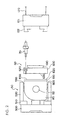
- FIG. 5 is an explanatory view showing the detail of the jig plate 60
- FIG. 6 is an explanatory view of a standard chuck 121 of the second main spindle.
- the jig plate 60 comprises a main body 600 and an inverse tapered portion 610.
- a bolt 620 is inserted to each of the bolt holes 624.
- a C-shaped retaining ring 622 is fitted in order to prevent dropping of the bolt 620.
- Three notches 614 are provided to the inverse tapered portion 610.
- the chuck claw 122 of the secondmain spindle 120 is provided with three chuck claws that pass through the notches 614 of the inverse tapered portion 610. Therefore, when the second main spindle 120 advances to the side of the first main spindle 110, the rotation phase of the second main spindle is brought into unity with the angle position so that the chuck claws 122 of the chuck 121 of the second main spindle pass through the notches 614 of the inverse tapered portion 610 of the jig plate 60.
- the second main spindle is turned 60 degrees to perform chucking, so that the tapered surface 612 of the inverse tapered portion 610 is steadily engaged with the tapered surface 122 of the chuck claw 122 of the second main spindle.
- jig plates having different sizes and shapes of the main body 600 of the jig plate 60 are prepared, with a common size and shape for the inverse tapered portion 610. Therefore, it is possible to correspond to various works without the need for stage exchange of the second main spindle.
- the shape of the fixing surface 630 of the work, the arrangement of the bolt 620 for fixing of the main body 600 or the like may be varied to correspond to the shape and size of the work.
- the jig plate of the present invention is capable of performing automatic machining to the irregular shaped work mounted thereto.
- the work is not irregular shaped, it is attached to the jig plate using a bolt for fixing, so that finishing with higher precision can be performed.
Landscapes
- Engineering & Computer Science (AREA)
- Mechanical Engineering (AREA)
- Jigs For Machine Tools (AREA)
- Turning (AREA)
- Automatic Tool Replacement In Machine Tools (AREA)
- Multi-Process Working Machines And Systems (AREA)
Abstract
Description
Claims (3)
- A jig plate gripped by a main spindle of a lathe-type machine tool, comprising:a main body provided with a fixing surface to be detachably fixed to an end surface of a work, andan inverse tapered portion provided to the opposite side of the fixing surface of the main body and gripped by a chuck of the main spindle.
- The jig plate according to claim 1, wherein the inverse tapered portion has a common size and shape, and the main body corresponds to a size and shape of the work.
- The jig plate according to claim 1, wherein the means for detachably fixing the main body of the jig plate to the end surface of the work is a bolt being inserted to the main body.
Applications Claiming Priority (2)
| Application Number | Priority Date | Filing Date | Title |
|---|---|---|---|
| JP2003348159 | 2003-10-07 | ||
| JP2003348159A JP4336558B2 (en) | 2003-10-07 | 2003-10-07 | Jig plate |
Publications (2)
| Publication Number | Publication Date |
|---|---|
| EP1522379A1 true EP1522379A1 (en) | 2005-04-13 |
| EP1522379B1 EP1522379B1 (en) | 2007-03-14 |
Family
ID=34309204
Family Applications (1)
| Application Number | Title | Priority Date | Filing Date |
|---|---|---|---|
| EP04022889A Expired - Lifetime EP1522379B1 (en) | 2003-10-07 | 2004-09-25 | Jig plate for a workpiece to be machined |
Country Status (5)
| Country | Link |
|---|---|
| US (1) | US7108465B2 (en) |
| EP (1) | EP1522379B1 (en) |
| JP (1) | JP4336558B2 (en) |
| CN (1) | CN1605430B (en) |
| DE (1) | DE602004005283T2 (en) |
Cited By (1)
| Publication number | Priority date | Publication date | Assignee | Title |
|---|---|---|---|---|
| CN101549463B (en) * | 2009-05-12 | 2011-05-04 | 芜湖中瑞汽车零部件有限公司 | Lathe clamper of automobile hind axle flange |
Families Citing this family (9)
| Publication number | Priority date | Publication date | Assignee | Title |
|---|---|---|---|---|
| US8262099B2 (en) * | 2006-08-02 | 2012-09-11 | Lockheed Martin Corporation | Apparatus for adapting a workpiece holding device to a machine tool |
| NL2002040C (en) * | 2008-09-30 | 2010-03-31 | Pex Rent B V | COMPOSITION AND METHOD FOR MILLING AN OBJECT WITH A MILLING MACHINE |
| TWI496652B (en) * | 2009-07-09 | 2015-08-21 | Citizen Holdings Co Ltd | Processing materials and holding institutions |
| KR101836244B1 (en) * | 2012-10-26 | 2018-03-09 | 현대자동차 주식회사 | Processing device having clamp device |
| CN103846692A (en) * | 2012-12-01 | 2014-06-11 | 中国航空工业标准件制造有限责任公司 | Clamping and positioning device for machining cylinder bolts of large diesel engines |
| CN103071832B (en) * | 2013-01-29 | 2015-07-08 | 昌辉汽车电器(黄山)股份公司 | Drilling jig |
| CN103921143A (en) * | 2014-05-06 | 2014-07-16 | 哈尔滨建成集团有限公司 | Turning tool for left-and-right-wing insert |
| CN108098538A (en) * | 2017-11-30 | 2018-06-01 | 江门市兆业科技有限公司 | A kind of part processing sanding apparatus |
| CN111565887A (en) * | 2018-02-16 | 2020-08-21 | 株式会社北川铁工所 | Chuck mechanism and top claw |
Citations (4)
| Publication number | Priority date | Publication date | Assignee | Title |
|---|---|---|---|---|
| WO1996031308A1 (en) * | 1995-04-06 | 1996-10-10 | Roplan Ab | Gripping device for workpiece |
| DE19523787A1 (en) * | 1995-06-29 | 1997-01-02 | Iobb Produktideen Vorausentwic | Manipulation tool for machine tool, esp. for NC-milling machine |
| US6139002A (en) * | 1997-04-22 | 2000-10-31 | Stark; Emil | Single-nipple clamping with correct positioning |
| JP2001157937A (en) * | 1999-12-02 | 2001-06-12 | Nabeya Iron & Tool Works Ltd | Tightening apparatus |
Family Cites Families (20)
| Publication number | Priority date | Publication date | Assignee | Title |
|---|---|---|---|---|
| US986829A (en) * | 1909-07-13 | 1911-03-14 | Frank H Kasperson | Tool holding and driving device. |
| US1340741A (en) * | 1918-04-27 | 1920-05-18 | Charles F Schmelzer | Milling-machine attachment |
| DE1602763B1 (en) * | 1967-02-18 | 1970-07-09 | Forkardt Paul Kg | Fixing nut for clamping tools |
| US4221391A (en) * | 1978-11-06 | 1980-09-09 | Dutton Anthony E | Multiple segmented chuck jaw |
| JPS6176249A (en) * | 1984-09-24 | 1986-04-18 | Toyoda Mach Works Ltd | Pallet changer |
| US4662043A (en) * | 1985-01-10 | 1987-05-05 | Sheffer Collet Company | Project plate system |
| US4688810A (en) * | 1986-04-15 | 1987-08-25 | Sheffer Collet Company | Support for a chuck |
| DE3533078C1 (en) * | 1985-09-17 | 1987-02-19 | Gildemeister Ag | Jaw changing device |
| DE3729601C1 (en) * | 1987-09-04 | 1988-10-27 | Erowa Ag | Device for clamping a workpiece or tool |
| ES2044640T3 (en) * | 1987-09-24 | 1994-01-01 | Buechler B Set Ag | PROCEDURE FOR THE MANUFACTURE OF A PALLET FOR THE RECEPTION OF WORK PIECES. |
| GB2272656A (en) * | 1992-11-21 | 1994-05-25 | Ian James Durrant | Offset chuck adaptor |
| DE4307342C2 (en) * | 1993-03-09 | 1994-12-08 | Erowa Ag | Device for the position-defined clamping of a workpiece at the workplace of a processing machine |
| DE19515644A1 (en) * | 1995-04-28 | 1996-10-31 | Hell Ag Linotype | Clamping element for machines with rotating jaw chuck |
| US5893689A (en) * | 1997-08-07 | 1999-04-13 | Juhasz; John C | Drill bit adapter |
| DE19809689A1 (en) * | 1998-03-06 | 1999-09-09 | 3R Syst Int Ab | Headstock coupling used for workpiece pallet positioning in machine tools e.g. automatic lathe, milling machines |
| IL125766A (en) * | 1998-08-13 | 2002-12-01 | Iscar Ltd | Tool shank and a replaceable cutting head for mounting thereon in a self-clamping manner |
| JP4052764B2 (en) | 1999-04-20 | 2008-02-27 | 本田技研工業株式会社 | Whole surface machining method |
| DK1068918T3 (en) * | 1999-07-14 | 2005-02-28 | Erowa Ag | Device for position-defining clamping of a workpiece in a working machine's working area |
| US6357974B1 (en) * | 1999-12-14 | 2002-03-19 | Troy L. Robins | Quick release drill chuck |
| TW592882B (en) * | 2001-12-19 | 2004-06-21 | Erowa Ag | Clamping apparatus with a clamping chuck and a work piece carrier releasable connectable thereto |
-
2003
- 2003-10-07 JP JP2003348159A patent/JP4336558B2/en not_active Expired - Fee Related
-
2004
- 2004-09-25 DE DE602004005283T patent/DE602004005283T2/en not_active Expired - Lifetime
- 2004-09-25 EP EP04022889A patent/EP1522379B1/en not_active Expired - Lifetime
- 2004-09-27 US US10/950,980 patent/US7108465B2/en not_active Expired - Fee Related
- 2004-10-08 CN CN2004100849683A patent/CN1605430B/en not_active Expired - Fee Related
Patent Citations (4)
| Publication number | Priority date | Publication date | Assignee | Title |
|---|---|---|---|---|
| WO1996031308A1 (en) * | 1995-04-06 | 1996-10-10 | Roplan Ab | Gripping device for workpiece |
| DE19523787A1 (en) * | 1995-06-29 | 1997-01-02 | Iobb Produktideen Vorausentwic | Manipulation tool for machine tool, esp. for NC-milling machine |
| US6139002A (en) * | 1997-04-22 | 2000-10-31 | Stark; Emil | Single-nipple clamping with correct positioning |
| JP2001157937A (en) * | 1999-12-02 | 2001-06-12 | Nabeya Iron & Tool Works Ltd | Tightening apparatus |
Non-Patent Citations (1)
| Title |
|---|
| PATENT ABSTRACTS OF JAPAN vol. 2000, no. 23 10 February 2001 (2001-02-10) * |
Cited By (1)
| Publication number | Priority date | Publication date | Assignee | Title |
|---|---|---|---|---|
| CN101549463B (en) * | 2009-05-12 | 2011-05-04 | 芜湖中瑞汽车零部件有限公司 | Lathe clamper of automobile hind axle flange |
Also Published As
| Publication number | Publication date |
|---|---|
| DE602004005283T2 (en) | 2007-11-22 |
| US20050073116A1 (en) | 2005-04-07 |
| CN1605430A (en) | 2005-04-13 |
| EP1522379B1 (en) | 2007-03-14 |
| JP2005111598A (en) | 2005-04-28 |
| JP4336558B2 (en) | 2009-09-30 |
| CN1605430B (en) | 2010-04-28 |
| DE602004005283D1 (en) | 2007-04-26 |
| US7108465B2 (en) | 2006-09-19 |
Similar Documents
| Publication | Publication Date | Title |
|---|---|---|
| US7243407B2 (en) | Modular turret-style base plate system for CNC machines | |
| EP2616202B1 (en) | Workholding apparatus for workpiece transfer | |
| US7108465B2 (en) | Jig plate | |
| JPH01222806A (en) | Chuck device | |
| US6768076B2 (en) | Precision base and fixture adapter set-up | |
| JP2004142076A (en) | Method for determining phase of workpiece in machine tool, and its apparatus | |
| US5984321A (en) | Universal quick jaws | |
| JP2002200537A (en) | Cylinder head cutting equipment | |
| JP4199630B2 (en) | Automatic 6-side machining system | |
| CN219484920U (en) | Multipurpose quick-change clamp for flexible processing | |
| JP7383278B2 (en) | Work holder for processing machines | |
| CN107073664B (en) | Component holding device and machine tool provided with the same | |
| JP4705729B2 (en) | Workpiece gripping change device in lathe and two-spindle facing lathe equipped with the gripping change device | |
| JP2005118889A (en) | Torque wrench tool | |
| JPH0631933U (en) | Work pusher | |
| US8262099B2 (en) | Apparatus for adapting a workpiece holding device to a machine tool | |
| US20260138194A1 (en) | Hydraulic chuck for jaw molding | |
| EP4442392B1 (en) | Hydraulic chuck for easy jaw formation thereon | |
| CN223210507U (en) | Positioning chuck of multiple spot floating centre gripping | |
| JPH11188513A (en) | Automatic chuck changing method and automatic chuck changing device for machine tool | |
| KR20000029444A (en) | Method of machining crankshaft | |
| US11883919B2 (en) | Automatic fixture replacement mechanism for machine tool | |
| JP2584424Y2 (en) | Eccentric machining chuck mechanism | |
| EP4201584A1 (en) | Machining chuck for a measuring and machining station, especially for metal casts | |
| JPH01146633A (en) | Workpiece mounting jig |
Legal Events
| Date | Code | Title | Description |
|---|---|---|---|
| PUAI | Public reference made under article 153(3) epc to a published international application that has entered the european phase |
Free format text: ORIGINAL CODE: 0009012 |
|
| AK | Designated contracting states |
Kind code of ref document: A1 Designated state(s): AT BE BG CH CY CZ DE DK EE ES FI FR GB GR HU IE IT LI LU MC NL PL PT RO SE SI SK TR |
|
| AX | Request for extension of the european patent |
Extension state: AL HR LT LV MK |
|
| 17P | Request for examination filed |
Effective date: 20050520 |
|
| AKX | Designation fees paid |
Designated state(s): DE FR GB IT |
|
| GRAP | Despatch of communication of intention to grant a patent |
Free format text: ORIGINAL CODE: EPIDOSNIGR1 |
|
| GRAS | Grant fee paid |
Free format text: ORIGINAL CODE: EPIDOSNIGR3 |
|
| GRAA | (expected) grant |
Free format text: ORIGINAL CODE: 0009210 |
|
| AK | Designated contracting states |
Kind code of ref document: B1 Designated state(s): DE FR GB IT |
|
| REG | Reference to a national code |
Ref country code: GB Ref legal event code: FG4D |
|
| REF | Corresponds to: |
Ref document number: 602004005283 Country of ref document: DE Date of ref document: 20070426 Kind code of ref document: P |
|
| ET | Fr: translation filed | ||
| PLBE | No opposition filed within time limit |
Free format text: ORIGINAL CODE: 0009261 |
|
| STAA | Information on the status of an ep patent application or granted ep patent |
Free format text: STATUS: NO OPPOSITION FILED WITHIN TIME LIMIT |
|
| 26N | No opposition filed |
Effective date: 20071217 |
|
| REG | Reference to a national code |
Ref country code: FR Ref legal event code: PLFP Year of fee payment: 12 |
|
| PGFP | Annual fee paid to national office [announced via postgrant information from national office to epo] |
Ref country code: GB Payment date: 20150923 Year of fee payment: 12 Ref country code: DE Payment date: 20150922 Year of fee payment: 12 |
|
| PGFP | Annual fee paid to national office [announced via postgrant information from national office to epo] |
Ref country code: FR Payment date: 20150811 Year of fee payment: 12 |
|
| PGFP | Annual fee paid to national office [announced via postgrant information from national office to epo] |
Ref country code: IT Payment date: 20150925 Year of fee payment: 12 |
|
| REG | Reference to a national code |
Ref country code: DE Ref legal event code: R119 Ref document number: 602004005283 Country of ref document: DE |
|
| GBPC | Gb: european patent ceased through non-payment of renewal fee |
Effective date: 20160925 |
|
| REG | Reference to a national code |
Ref country code: FR Ref legal event code: ST Effective date: 20170531 |
|
| PG25 | Lapsed in a contracting state [announced via postgrant information from national office to epo] |
Ref country code: DE Free format text: LAPSE BECAUSE OF NON-PAYMENT OF DUE FEES Effective date: 20170401 Ref country code: GB Free format text: LAPSE BECAUSE OF NON-PAYMENT OF DUE FEES Effective date: 20160925 Ref country code: FR Free format text: LAPSE BECAUSE OF NON-PAYMENT OF DUE FEES Effective date: 20160930 |
|
| PG25 | Lapsed in a contracting state [announced via postgrant information from national office to epo] |
Ref country code: IT Free format text: LAPSE BECAUSE OF NON-PAYMENT OF DUE FEES Effective date: 20160925 |