EP1522372A1 - Temperature indicating consumable - Google Patents
Temperature indicating consumable Download PDFInfo
- Publication number
- EP1522372A1 EP1522372A1 EP04019913A EP04019913A EP1522372A1 EP 1522372 A1 EP1522372 A1 EP 1522372A1 EP 04019913 A EP04019913 A EP 04019913A EP 04019913 A EP04019913 A EP 04019913A EP 1522372 A1 EP1522372 A1 EP 1522372A1
- Authority
- EP
- European Patent Office
- Prior art keywords
- temperature
- shielding cup
- torch
- plasma
- consumable
- Prior art date
- Legal status (The legal status is an assumption and is not a legal conclusion. Google has not performed a legal analysis and makes no representation as to the accuracy of the status listed.)
- Withdrawn
Links
- 238000005520 cutting process Methods 0.000 claims abstract description 37
- 239000011248 coating agent Substances 0.000 claims abstract description 10
- 238000000576 coating method Methods 0.000 claims abstract description 10
- 238000010438 heat treatment Methods 0.000 claims description 6
- 238000003466 welding Methods 0.000 abstract description 8
- 238000013021 overheating Methods 0.000 abstract description 6
- 238000000034 method Methods 0.000 abstract description 4
- 238000010276 construction Methods 0.000 description 6
- 230000006698 induction Effects 0.000 description 4
- 230000005540 biological transmission Effects 0.000 description 2
- 238000004519 manufacturing process Methods 0.000 description 2
- 239000000463 material Substances 0.000 description 2
- 230000003685 thermal hair damage Effects 0.000 description 2
- 238000012546 transfer Methods 0.000 description 2
- 238000005493 welding type Methods 0.000 description 2
- 239000003086 colorant Substances 0.000 description 1
- 230000006378 damage Effects 0.000 description 1
- 230000001419 dependent effect Effects 0.000 description 1
- 238000013461 design Methods 0.000 description 1
- 238000010891 electric arc Methods 0.000 description 1
- 238000012986 modification Methods 0.000 description 1
- 230000004048 modification Effects 0.000 description 1
- 239000007858 starting material Substances 0.000 description 1
Images

Classifications
-
- H—ELECTRICITY
- H05—ELECTRIC TECHNIQUES NOT OTHERWISE PROVIDED FOR
- H05H—PLASMA TECHNIQUE; PRODUCTION OF ACCELERATED ELECTRICALLY-CHARGED PARTICLES OR OF NEUTRONS; PRODUCTION OR ACCELERATION OF NEUTRAL MOLECULAR OR ATOMIC BEAMS
- H05H1/00—Generating plasma; Handling plasma
- H05H1/24—Generating plasma
- H05H1/26—Plasma torches
- H05H1/32—Plasma torches using an arc
- H05H1/34—Details, e.g. electrodes, nozzles
-
- B—PERFORMING OPERATIONS; TRANSPORTING
- B23—MACHINE TOOLS; METAL-WORKING NOT OTHERWISE PROVIDED FOR
- B23K—SOLDERING OR UNSOLDERING; WELDING; CLADDING OR PLATING BY SOLDERING OR WELDING; CUTTING BY APPLYING HEAT LOCALLY, e.g. FLAME CUTTING; WORKING BY LASER BEAM
- B23K9/00—Arc welding or cutting
- B23K9/24—Features related to electrodes
- B23K9/26—Accessories for electrodes, e.g. ignition tips
-
- B—PERFORMING OPERATIONS; TRANSPORTING
- B23—MACHINE TOOLS; METAL-WORKING NOT OTHERWISE PROVIDED FOR
- B23K—SOLDERING OR UNSOLDERING; WELDING; CLADDING OR PLATING BY SOLDERING OR WELDING; CUTTING BY APPLYING HEAT LOCALLY, e.g. FLAME CUTTING; WORKING BY LASER BEAM
- B23K9/00—Arc welding or cutting
- B23K9/24—Features related to electrodes
- B23K9/28—Supporting devices for electrodes
- B23K9/29—Supporting devices adapted for making use of shielding means
- B23K9/291—Supporting devices adapted for making use of shielding means the shielding means being a gas
- B23K9/296—Supporting devices adapted for making use of shielding means the shielding means being a gas using non-consumable electrodes
-
- B—PERFORMING OPERATIONS; TRANSPORTING
- B23—MACHINE TOOLS; METAL-WORKING NOT OTHERWISE PROVIDED FOR
- B23K—SOLDERING OR UNSOLDERING; WELDING; CLADDING OR PLATING BY SOLDERING OR WELDING; CUTTING BY APPLYING HEAT LOCALLY, e.g. FLAME CUTTING; WORKING BY LASER BEAM
- B23K35/00—Rods, electrodes, materials, or media, for use in soldering, welding, or cutting
-
- C—CHEMISTRY; METALLURGY
- C21—METALLURGY OF IRON
- C21D—MODIFYING THE PHYSICAL STRUCTURE OF FERROUS METALS; GENERAL DEVICES FOR HEAT TREATMENT OF FERROUS OR NON-FERROUS METALS OR ALLOYS; MAKING METAL MALLEABLE, e.g. BY DECARBURISATION OR TEMPERING
- C21D11/00—Process control or regulation for heat treatments
-
- H—ELECTRICITY
- H05—ELECTRIC TECHNIQUES NOT OTHERWISE PROVIDED FOR
- H05H—PLASMA TECHNIQUE; PRODUCTION OF ACCELERATED ELECTRICALLY-CHARGED PARTICLES OR OF NEUTRONS; PRODUCTION OR ACCELERATION OF NEUTRAL MOLECULAR OR ATOMIC BEAMS
- H05H1/00—Generating plasma; Handling plasma
- H05H1/24—Generating plasma
- H05H1/26—Plasma torches
- H05H1/32—Plasma torches using an arc
- H05H1/34—Details, e.g. electrodes, nozzles
- H05H1/3473—Safety means
-
- H—ELECTRICITY
- H05—ELECTRIC TECHNIQUES NOT OTHERWISE PROVIDED FOR
- H05H—PLASMA TECHNIQUE; PRODUCTION OF ACCELERATED ELECTRICALLY-CHARGED PARTICLES OR OF NEUTRONS; PRODUCTION OR ACCELERATION OF NEUTRAL MOLECULAR OR ATOMIC BEAMS
- H05H1/00—Generating plasma; Handling plasma
- H05H1/24—Generating plasma
- H05H1/26—Plasma torches
- H05H1/32—Plasma torches using an arc
- H05H1/34—Details, e.g. electrodes, nozzles
- H05H1/3494—Means for controlling discharge parameters
Definitions
- the present invention relates generally to plasma cutting systems and other high power output welding-type systems such as welding and induction heating systems and, more particularly, to a temperature indicating consumable for use with such systems.
- Plasma cutting is a process in which an electric arc is used to cut a workpiece.
- Plasma cutters typically include a power source, an air supply, and a torch.
- the torch, or plasma torch is used to create and maintain the plasma arc that performs the cutting.
- a plasma cutting power source receives an input voltage from a transmission power line or generator and provides an output voltage to a pair of output terminals, one of which is connected to an electrode and the other of which is connected to the workpiece.
- An air supply is used with most plasma cutters to help start the arc, provide the plasma gas to the torch, and cool the torch.
- a movable or fixed electrode or consumable serves as a cathode and a fixed nozzle serves as an anode.
- the air supply moves the electrode and as the electrode moves away from the nozzle, it opens the nozzle, and a plasma jet is created.
- the plasma jet causes the arc to transfer to the work piece, and thus initiates the cutting process.
- a high frequency starter is used to initiate the cutting process.
- the present invention is directed to a method and apparatus for indicating the temperature of consumables overcoming the aforementioned drawbacks.
- a method and apparatus for indicating the temperature of a torch consumable includes a shielding cup constructed to be attached to a plasma torch and constructed to indicate a temperature of the shielding cup during some phase of a welding/cutting process.
- the coating indicates to a user when the temperature of the consumable is beyond a preferred operating range, thereby preventing excessive wear of the consumables.
- a shielding cup having a body with an outer surface, a first end connectable to a torch, and a second end connectable to a shield.
- a thermally responsive coating is formed on the shielding cup and provides an indication of the temperature of the shielding cup. As such, an operator is informed that the temperature of the consumable assembly has reached a maximum operating temperature.
- Such a construction allows an operator to suspend operation prior to thermal damage to the consumables.
- a plasma cutter in accordance with another aspect of the present invention, includes a power source configured to condition power into a form usable for a plasma cutting process.
- a torch is connected to the power source and configured to effectuate the plasma cutting process and includes a shielding cup and a temperature indicator connected thereto.
- the temperature indicator is configured to indicate a temperature of the shielding cup so that a user can suspend the cutting process before overheating occurs.
- a plasma torch consumable kit that includes an electrode, a tip, and a shielding cup constructed to provide a temperature indication.
- a plasma torch consumable kit allows a user to replace a similar consumable with a consumable assembly that includes a temperature indicator.
- a method of manufacturing a plasma torch consumable includes the steps of providing a shielding cup having a body and forming the shielding cup to indicate temperature. Such a construction allows a user to readily observe the point at which the shielding cup has reached a maximum operating temperature.
- the present invention is directed to a temperature indicating consumable.
- the present invention is directed to a plasma torch consumable set that indicates a temperature to an operator.
- the temperature that is indicated to the operator is indicative of excessive temperature and is consumable set specific. That is, in a preferred embodiment, one consumable set will operate at one temperature and another consumable set may be constructed to operate at, and indicate, another temperature.
- indicating an operating temperature of a consumable will be equivalently applicable to other high power output systems such as welding systems and induction heating systems.
- the plasma cutting system 10 is a high voltage system with maximum open circuit output voltages ranging from approximately 230 Volts Direct Current (VDC) to over 300 VDC.
- the plasma cutting system 10 includes a power source 12 to condition raw power and regulate/control the cutting process.
- the power source 12 includes a processor that, as will be described, receives operational feedback and controls the plasma cutting system 10 accordingly.
- Power source 12 includes a lifting means, such as a handle 14 which effectuates transportation from one site to another.
- Connected to the power source 12 is a torch 16 via cable 18.- The cable 18 provides the torch 16 with power and serves as a communications link between the torch 16 and power source 12.
- a work clamp 20 which is designed to hold a workpiece (not shown) to be cut and provide a grounding path.
- a cable 22 designed to provide a return path for the cutting current from the torch through the workpiece and the work clamp 20.
- power cable 24 Extending from a rear portion of power source 12 is power cable 24 having plug 26 for connecting the power source 12 to a portable power supply 28 or a transmission power receptacle (not shown).
- Power source 12 further includes an ON/OFF switch 30.
- torch 16 is placed in close proximity to a workpiece connected to clamp 20.
- a user may then activate a trigger (not shown) on the torch 16 to deliver power to the torch 16 to initiate a pilot arc.
- a cutting arc is generated and the user may then slowly move the torch across the workpiece to cut the workpiece.
- the user may adjust the torch speed to reduce spark splatter and provide a more-penetrating cut.
- Gas is supplied to torch 16 from a pressurized gas source 33 or from an internal air compressor.
- Plasma torch 16 is defined by a torch body 36 that is designed to receive a shielding cup 38.
- Shielding cup 38 is connected to torch body 36 so as to define a gas chamber 40 that, as will be described in greater detail below, allows for the charging of the gas to a plasma and passage of the plasma therethrough.
- electrode 42 Centrally disposed within gas chamber 40 and connected to torch body 36 is electrode 42.
- Electrode 42 is removably connected to torch body 36 and is specifically designed for a particular plasma cutting process.
- Collectively, electrode 42, shielding cup 38, and a tip 44 form a consumable set 47.
- Torch 16 is constructed such that various consumable sets may be interchangeably connected depending upon the particular plasma cutting process to be carried out. Additionally, it is understood that electrode 42 and tip 44 can be worn, or consumed, at a greater pace than shielding cup 38 so that the shielding cup can be repeatedly used with replacement tips and electrodes before it would require replacement.
- Tip 44 is connected to shielding cup 38 and is constructed to form a nozzle 46.
- gas is injected into chamber 40 via passages 48 and is superheated to a plasma state.
- An O-ring 49 forms a seal between shielding cup 38 and torch body 36 and prevents plasma from exiting chamber 40 therebetween.
- the plasma is forced out of the chamber through nozzle 46 and out of tip 44 via opening or aperture 50.
- Nozzle 46 is designed to focus the velocity as well as the heat of an arc that is created between a workpiece (not shown) and electrode 42.
- Electrode 42 is constructed such that the arc extends across an arc path 52 out of the consumable through opening 50.
- Torch 16 also includes, preferably, an indicator band 54 formed about shielding cup 38 that is designed to indicate to a user the operating temperature of consumable set 47 connected to torch body 36.
- the indicator band 54 is designed to glow or change colors in order to provide an operator with an indication that the consumable set has reached a predetermined temperature.
- the predetermined temperature is the temperature at which further operation of consumable set 47 would result in overheating of consumable set 47. Additionally, it is understood that in the event consumable set 47 is reconfigured to operate at a higher temperature, i.e. by inserting a different electrode or tip, indicator band 54 could also be changed so as to indicate a second operating temperature.
- shielding cup 38 include additional indicator bands such as a second indicator band 55 to indicate a second operating temperature. Such a construction would allow the shielding cup 38 of consumable set 47 to indicate multiple temperatures, such as a first and a second operating temperature. It is also equally understood and within the scope of the claims that indicator bands 54, 55 be configured to indicate temperature in any number of ways including, but not limited to, glowing, changing color, or emitting odor. Such indicators are only by way of example and are not intended to limit the scope of the claims included herein.
- Indicator band 54 by being placed directly about shielding cup 38, is closely located to an operator's focus point during operation of the torch. As such, when consumable set 47 reaches a maximum operating temperature, an operator is nearly instantaneously notified of such a condition and can stop the cutting process. Such a construction prevents overheating of the consumable set. Additionally, since cut quality is partially dependent on consumable quality, an operator can maximize the quality of a cut by stopping the cutting process prior to overheating of the consumable set.
- welding devices not only includes plasma torches, but also includes any system that requires high power outputs, such as heating and cutting systems. Therefore, the present invention is equivalently applicable with any device requiring high power output, including welders, plasma cutters, induction heaters, and the like.
- Reference to welding power, welding-type power, or welders generally, includes welding, cutting, or heating power.
- Description of a welding apparatus illustrates just one embodiment in which the present invention may be implemented. The present invention is equivalently applicable with many high power systems, such as cutting and induction heating systems, or any similar systems.
- a shielding cup has a body with an outer surface, a first end connectable to a torch, and a second end connectable to a shield.
- a thermally responsive coating is formed on the shielding cup and provides an indication of the temperature. As such, an operator is informed that the temperature of the consumable assembly has reached a maximum operating temperature.
- Such a construction allows an operator to suspend operation prior to thermal damage to the consumables.
- a plasma cutter in accordance with another embodiment of the present invention, includes a power source configured to condition power into a form usable for a plasma cutting process.
- a torch is connected to the power source and configured to effectuate the plasma cutting process and includes a shielding cup and a temperature indicator connected thereto.
- the temperature indicator is configured to indicate a temperature of the shielding cup so that a user can suspend the cutting process before overheating occurs.
- a plasma torch consumable kit includes an electrode, a tip, and a shielding cup constructed to provide a temperature indication.
- a kit allows a user to replace a similar consumable with a consumable assembly that includes a temperature indicator.
- a method of manufacturing a plasma torch consumable includes the steps of providing a shielding cup having a body and forming the shielding cup to indicate temperature. Such a construction allows a user to readily observe the point at which the shielding cup has reached a maximum operating temperature.
Landscapes
- Engineering & Computer Science (AREA)
- Physics & Mathematics (AREA)
- Plasma & Fusion (AREA)
- Spectroscopy & Molecular Physics (AREA)
- Mechanical Engineering (AREA)
- Arc Welding In General (AREA)
- Plasma Technology (AREA)
- Auxiliary Devices For And Details Of Packaging Control (AREA)
Abstract
Description
- The present invention relates generally to plasma cutting systems and other high power output welding-type systems such as welding and induction heating systems and, more particularly, to a temperature indicating consumable for use with such systems.
- Plasma cutting is a process in which an electric arc is used to cut a workpiece. Plasma cutters typically include a power source, an air supply, and a torch. The torch, or plasma torch, is used to create and maintain the plasma arc that performs the cutting. A plasma cutting power source receives an input voltage from a transmission power line or generator and provides an output voltage to a pair of output terminals, one of which is connected to an electrode and the other of which is connected to the workpiece.
- An air supply is used with most plasma cutters to help start the arc, provide the plasma gas to the torch, and cool the torch. A movable or fixed electrode or consumable serves as a cathode and a fixed nozzle serves as an anode. The air supply moves the electrode and as the electrode moves away from the nozzle, it opens the nozzle, and a plasma jet is created. The plasma jet causes the arc to transfer to the work piece, and thus initiates the cutting process. In other plasma cutting systems, a high frequency starter is used to initiate the cutting process.
- During the cutting process, as the arc transfers on the plasma from the electrode to the workpiece, heat is generated. The amount of heat generated during operation is partially determined by the type of material being worked, the power output required to work the material, and the type of consumable required to effectuate the desired work. Operating the torch at increased temperatures can effectively shorten the working life of a consumable, and if not addressed, can result in damage to the torch body and/or the power source. Additionally, plasma cutting with an overheated consumable also results in poor cut quality.
- It would therefore be desirable to design a consumable which indicates an operating temperature of the consumable.
- The present invention is directed to a method and apparatus for indicating the temperature of consumables overcoming the aforementioned drawbacks.
- A method and apparatus for indicating the temperature of a torch consumable is disclosed. The invention includes a shielding cup constructed to be attached to a plasma torch and constructed to indicate a temperature of the shielding cup during some phase of a welding/cutting process. The coating indicates to a user when the temperature of the consumable is beyond a preferred operating range, thereby preventing excessive wear of the consumables.
- Therefore, in accordance with one aspect of the present invention, a shielding cup is disclosed having a body with an outer surface, a first end connectable to a torch, and a second end connectable to a shield. A thermally responsive coating is formed on the shielding cup and provides an indication of the temperature of the shielding cup. As such, an operator is informed that the temperature of the consumable assembly has reached a maximum operating temperature. Such a construction allows an operator to suspend operation prior to thermal damage to the consumables.
- In accordance with another aspect of the present invention, a plasma cutter is disclosed that includes a power source configured to condition power into a form usable for a plasma cutting process. A torch is connected to the power source and configured to effectuate the plasma cutting process and includes a shielding cup and a temperature indicator connected thereto. The temperature indicator is configured to indicate a temperature of the shielding cup so that a user can suspend the cutting process before overheating occurs.
- According to another aspect of the present invention, a plasma torch consumable kit is disclosed that includes an electrode, a tip, and a shielding cup constructed to provide a temperature indication. Such a kit allows a user to replace a similar consumable with a consumable assembly that includes a temperature indicator.
- In accordance with a further aspect of the present invention, a method of manufacturing a plasma torch consumable is disclosed that includes the steps of providing a shielding cup having a body and forming the shielding cup to indicate temperature. Such a construction allows a user to readily observe the point at which the shielding cup has reached a maximum operating temperature.
- Various other features, objects and advantages of the present invention will be made apparent from the following detailed description and the drawings.
- The drawings illustrate one preferred embodiment presently contemplated for carrying out the invention.
- In the drawings:
- Fig. 1 is a perspective view of one plasma cutting system incorporating the present invention.
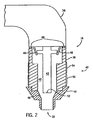
- Fig. 2 is a cross-sectional view of a plasma torch consumable constructed in accordance with the present invention.
-
- The present invention is directed to a temperature indicating consumable. As will be described below, the present invention is directed to a plasma torch consumable set that indicates a temperature to an operator. The temperature that is indicated to the operator is indicative of excessive temperature and is consumable set specific. That is, in a preferred embodiment, one consumable set will operate at one temperature and another consumable set may be constructed to operate at, and indicate, another temperature. One skilled in the art will readily appreciate that indicating an operating temperature of a consumable will be equivalently applicable to other high power output systems such as welding systems and induction heating systems.
- Referring to Fig. 1, a
plasma cutting system 10 is shown. The plasma cutting system is a high voltage system with maximum open circuit output voltages ranging from approximately 230 Volts Direct Current (VDC) to over 300 VDC. Theplasma cutting system 10 includes apower source 12 to condition raw power and regulate/control the cutting process. Specifically, thepower source 12 includes a processor that, as will be described, receives operational feedback and controls theplasma cutting system 10 accordingly.Power source 12 includes a lifting means, such as ahandle 14 which effectuates transportation from one site to another. Connected to thepower source 12 is atorch 16 via cable 18.- Thecable 18 provides thetorch 16 with power and serves as a communications link between thetorch 16 andpower source 12. - Also connected to
power source 12 is awork clamp 20 which is designed to hold a workpiece (not shown) to be cut and provide a grounding path. Connectingwork clamp 20 to thepower source 12 is acable 22 designed to provide a return path for the cutting current from the torch through the workpiece and thework clamp 20. Extending from a rear portion ofpower source 12 is power cable 24 havingplug 26 for connecting thepower source 12 to aportable power supply 28 or a transmission power receptacle (not shown).Power source 12 further includes an ON/OFF switch 30. - To effectuate cutting of a workpiece,
torch 16 is placed in close proximity to a workpiece connected toclamp 20. A user may then activate a trigger (not shown) on thetorch 16 to deliver power to thetorch 16 to initiate a pilot arc. Shortly thereafter, a cutting arc is generated and the user may then slowly move the torch across the workpiece to cut the workpiece. The user may adjust the torch speed to reduce spark splatter and provide a more-penetrating cut. Gas is supplied totorch 16 from a pressurized gas source 33 or from an internal air compressor. - Referring now to Fig. 2, a cross-section of a
plasma cutting torch 16 is shown.Plasma torch 16 is defined by atorch body 36 that is designed to receive ashielding cup 38.Shielding cup 38 is connected totorch body 36 so as to define agas chamber 40 that, as will be described in greater detail below, allows for the charging of the gas to a plasma and passage of the plasma therethrough. Centrally disposed withingas chamber 40 and connected totorch body 36 iselectrode 42. Electrode 42 is removably connected totorch body 36 and is specifically designed for a particular plasma cutting process. Collectively,electrode 42,shielding cup 38, and atip 44 form aconsumable set 47.Torch 16 is constructed such that various consumable sets may be interchangeably connected depending upon the particular plasma cutting process to be carried out. Additionally, it is understood thatelectrode 42 andtip 44 can be worn, or consumed, at a greater pace than shieldingcup 38 so that the shielding cup can be repeatedly used with replacement tips and electrodes before it would require replacement. -
Tip 44 is connected to shieldingcup 38 and is constructed to form anozzle 46. In operation, gas is injected intochamber 40 viapassages 48 and is superheated to a plasma state. An O-ring 49 forms a seal between shieldingcup 38 andtorch body 36 and prevents plasma from exitingchamber 40 therebetween. The plasma is forced out of the chamber throughnozzle 46 and out oftip 44 via opening oraperture 50.Nozzle 46 is designed to focus the velocity as well as the heat of an arc that is created between a workpiece (not shown) andelectrode 42.Electrode 42 is constructed such that the arc extends across anarc path 52 out of the consumable throughopening 50. -
Torch 16 also includes, preferably, anindicator band 54 formed about shieldingcup 38 that is designed to indicate to a user the operating temperature of consumable set 47 connected to torchbody 36. Theindicator band 54 is designed to glow or change colors in order to provide an operator with an indication that the consumable set has reached a predetermined temperature. The predetermined temperature, the indicated temperature, is the temperature at which further operation of consumable set 47 would result in overheating of consumable set 47. Additionally, it is understood that in the event consumable set 47 is reconfigured to operate at a higher temperature, i.e. by inserting a different electrode or tip,indicator band 54 could also be changed so as to indicate a second operating temperature. - It is equally understood and within the scope of the claims that shielding
cup 38 include additional indicator bands such as asecond indicator band 55 to indicate a second operating temperature. Such a construction would allow the shieldingcup 38 of consumable set 47 to indicate multiple temperatures, such as a first and a second operating temperature. It is also equally understood and within the scope of the claims thatindicator bands -
Indicator band 54, by being placed directly about shieldingcup 38, is closely located to an operator's focus point during operation of the torch. As such, when consumable set 47 reaches a maximum operating temperature, an operator is nearly instantaneously notified of such a condition and can stop the cutting process. Such a construction prevents overheating of the consumable set. Additionally, since cut quality is partially dependent on consumable quality, an operator can maximize the quality of a cut by stopping the cutting process prior to overheating of the consumable set. - As one skilled in the art will fully appreciate, the heretofore description of welding devices not only includes plasma torches, but also includes any system that requires high power outputs, such as heating and cutting systems. Therefore, the present invention is equivalently applicable with any device requiring high power output, including welders, plasma cutters, induction heaters, and the like. Reference to welding power, welding-type power, or welders generally, includes welding, cutting, or heating power. Description of a welding apparatus illustrates just one embodiment in which the present invention may be implemented. The present invention is equivalently applicable with many high power systems, such as cutting and induction heating systems, or any similar systems.
- Therefore, in accordance with one embodiment of the present invention, a shielding cup has a body with an outer surface, a first end connectable to a torch, and a second end connectable to a shield. A thermally responsive coating is formed on the shielding cup and provides an indication of the temperature. As such, an operator is informed that the temperature of the consumable assembly has reached a maximum operating temperature. Such a construction allows an operator to suspend operation prior to thermal damage to the consumables.
- In accordance with another embodiment of the present invention, a plasma cutter includes a power source configured to condition power into a form usable for a plasma cutting process. A torch is connected to the power source and configured to effectuate the plasma cutting process and includes a shielding cup and a temperature indicator connected thereto. The temperature indicator is configured to indicate a temperature of the shielding cup so that a user can suspend the cutting process before overheating occurs.
- According to another embodiment of the present invention, a plasma torch consumable kit includes an electrode, a tip, and a shielding cup constructed to provide a temperature indication. Such a kit allows a user to replace a similar consumable with a consumable assembly that includes a temperature indicator.
- In accordance with a further embodiment of the present invention, a method of manufacturing a plasma torch consumable includes the steps of providing a shielding cup having a body and forming the shielding cup to indicate temperature. Such a construction allows a user to readily observe the point at which the shielding cup has reached a maximum operating temperature.
- The present invention has been described in terms of the preferred embodiment, and it is recognized that equivalents, alternatives, and modifications, aside from those expressly stated, are possible and within the scope of the appending claims.
- The claims refer to examples of preferred embodiments of the invention. However, the invention also refers to the use of any single feature and subcombination of features which are disclosed in the claims, the description and/or the drawings.
Claims (9)
- A shielding cup comprising:a body having an outer surface;a first end connectable to a torch;a second end connectable to a shield; anda coating on at least one of the outer surface of the body, the first end, and the second end, the coating being thermally responsive so as to provide an indication of temperature.
- The shielding cup of claim 1 wherein the coating is further configured to emit an odor, a change in color, or a light to indicate temperature.
- The shielding cup of claim 1 wherein the coating is capable of indicating a range of temperatures.
- The shielding cup of claim 1 further comprising another coating on a portion of the shielding cup to provide an indication of another temperature.
- The shielding cup of claim 1 wherein the body further defines a gas chamber configured to support heating of a gas to a plasma state.
- The shielding cup of claim 1 wherein the gas chamber accommodates an electrode and a cutting tip therein.
- The shielding cup of claim 1 further comprising a sensor integrally formed with the shielding cup and constructed to communicate with a power source to limit power from the power source if the temperature exceeds a predetermined temperature.
- A plasma cutter comprising:a power source configured to condition power into a form usable for a plasma cutting process;a torch connected to the power source and configured to effectuate the plasma cutting process;a shielding cup connected to the torch; anda temperature indicator configured to indicate a temperature of the shielding cup in accordance with claim 1.
- A plasma torch consumable kit comprising;an electrode;a tip;a shielding cup constructed to provide a temperature indication in accordance with claim 1.
Applications Claiming Priority (2)
| Application Number | Priority Date | Filing Date | Title |
|---|---|---|---|
| US10/605,570 US7084367B2 (en) | 2003-10-09 | 2003-10-09 | Temperature indicating consumable |
| US605570 | 2003-10-09 |
Publications (1)
| Publication Number | Publication Date |
|---|---|
| EP1522372A1 true EP1522372A1 (en) | 2005-04-13 |
Family
ID=34312557
Family Applications (1)
| Application Number | Title | Priority Date | Filing Date |
|---|---|---|---|
| EP04019913A Withdrawn EP1522372A1 (en) | 2003-10-09 | 2004-08-23 | Temperature indicating consumable |
Country Status (4)
| Country | Link |
|---|---|
| US (1) | US7084367B2 (en) |
| EP (1) | EP1522372A1 (en) |
| CA (1) | CA2484435C (en) |
| MX (1) | MXPA04009935A (en) |
Cited By (1)
| Publication number | Priority date | Publication date | Assignee | Title |
|---|---|---|---|---|
| AT503646B1 (en) * | 2006-09-15 | 2007-12-15 | Fronius Int Gmbh | Water vapor plasma burner for cutting a workpiece, comprises a feed line for a liquid, a heating device, an evaporator for forming a gas from the liquid, a cathode detachably connected to a movably mounted piston rod, and a nozzle |
Families Citing this family (6)
| Publication number | Priority date | Publication date | Assignee | Title |
|---|---|---|---|---|
| US9636768B2 (en) * | 2012-12-14 | 2017-05-02 | Hobart Brothers Company | Devices and methods for providing information on a torch |
| MX392349B (en) | 2016-07-18 | 2025-03-24 | Victor Equipment Co | DETECTION OF CHANGE OF CONSUMABLE PART FOR PLASMA DEVICE. |
| US10616988B2 (en) | 2017-06-20 | 2020-04-07 | The Esab Group Inc. | Electromechanical linearly actuated electrode |
| US11267069B2 (en) | 2018-04-06 | 2022-03-08 | The Esab Group Inc. | Recognition of components for welding and cutting torches |
| DE102019108456B4 (en) * | 2019-04-01 | 2025-01-30 | Alexander Binzel Schweisstechnik Gmbh & Co. Kg | Welding device with a welding torch and with a device and a method for determining and outputting the surface temperature of the welding torch |
| US11213910B2 (en) | 2019-09-19 | 2022-01-04 | The Esab Group Inc. | Torch indicator apparatus and methods |
Citations (4)
| Publication number | Priority date | Publication date | Assignee | Title |
|---|---|---|---|---|
| US4678120A (en) * | 1983-11-22 | 1987-07-07 | Nippon Steel Corporation | Refractory flame-gunning apparatus |
| US4861963A (en) * | 1988-09-23 | 1989-08-29 | Emerson Electric Co. | Plasma arc torch disconnect and visible indicia means |
| US4928027A (en) * | 1987-08-20 | 1990-05-22 | The United States Of America As Represented By The Administrator Of The National Aeronautics And Space Administration | High temperature refractory member with radiation emissive overcoat |
| FR2836619A1 (en) * | 2002-02-28 | 2003-08-29 | Snecma Services | Instrument to control a thermal projection torch in real time by measuring the jet characteristics by a combined camera and pyrometer and computer analysis to determine the required feed parameter |
Family Cites Families (4)
| Publication number | Priority date | Publication date | Assignee | Title |
|---|---|---|---|---|
| US3773597A (en) * | 1971-08-10 | 1973-11-20 | American Velcro Inc | Heating apparatus |
| US4960992A (en) * | 1983-08-30 | 1990-10-02 | Research Corporation Technologies | Method and means for vaporizing liquids by means of heating a sample capillary tube for detection or analysis |
| US5266772A (en) * | 1991-11-14 | 1993-11-30 | Thermal Tech, Inc. | Flexible portable container for carrying and maintaining arc welding electrodes at use temperature and method for maintaining arc welding electrodes at use temperature |
| DE10040321A1 (en) * | 2000-08-17 | 2002-04-11 | Schott Glas | Temperature indicator |
-
2003
- 2003-10-09 US US10/605,570 patent/US7084367B2/en not_active Expired - Lifetime
-
2004
- 2004-08-23 EP EP04019913A patent/EP1522372A1/en not_active Withdrawn
- 2004-10-07 CA CA002484435A patent/CA2484435C/en not_active Expired - Fee Related
- 2004-10-08 MX MXPA04009935A patent/MXPA04009935A/en active IP Right Grant
Patent Citations (4)
| Publication number | Priority date | Publication date | Assignee | Title |
|---|---|---|---|---|
| US4678120A (en) * | 1983-11-22 | 1987-07-07 | Nippon Steel Corporation | Refractory flame-gunning apparatus |
| US4928027A (en) * | 1987-08-20 | 1990-05-22 | The United States Of America As Represented By The Administrator Of The National Aeronautics And Space Administration | High temperature refractory member with radiation emissive overcoat |
| US4861963A (en) * | 1988-09-23 | 1989-08-29 | Emerson Electric Co. | Plasma arc torch disconnect and visible indicia means |
| FR2836619A1 (en) * | 2002-02-28 | 2003-08-29 | Snecma Services | Instrument to control a thermal projection torch in real time by measuring the jet characteristics by a combined camera and pyrometer and computer analysis to determine the required feed parameter |
Cited By (2)
| Publication number | Priority date | Publication date | Assignee | Title |
|---|---|---|---|---|
| AT503646B1 (en) * | 2006-09-15 | 2007-12-15 | Fronius Int Gmbh | Water vapor plasma burner for cutting a workpiece, comprises a feed line for a liquid, a heating device, an evaporator for forming a gas from the liquid, a cathode detachably connected to a movably mounted piston rod, and a nozzle |
| US8455785B2 (en) | 2006-09-15 | 2013-06-04 | Fronius International Gmbh | Water-vapor plasma torch, and wear-detection and process-control method to be used with such a water-vapor plasma torch |
Also Published As
| Publication number | Publication date |
|---|---|
| CA2484435A1 (en) | 2005-04-09 |
| CA2484435C (en) | 2008-12-09 |
| US20050077270A1 (en) | 2005-04-14 |
| MXPA04009935A (en) | 2005-04-15 |
| US7084367B2 (en) | 2006-08-01 |
Similar Documents
| Publication | Publication Date | Title |
|---|---|---|
| US8395076B2 (en) | One-piece consumable assembly | |
| US7161111B2 (en) | Plasma torch having a quick-connect retaining cup | |
| US6992262B2 (en) | Method and apparatus for localized control of a plasma cutter | |
| US7186944B2 (en) | Method and apparatus for autodetection of plasma torch consumables | |
| WO2007114882A1 (en) | Plasma torch with post flow control | |
| EP0444346B1 (en) | Plasma arc torch having extended nozzle | |
| CN101516561B (en) | Method and apparatus for wireless remote control communication of a welder | |
| EP2953759B1 (en) | System and method for thermally working a workpiece using either a plasma torch or an oxy-fuel torch to be exchangeably mounted on one torch receptacle | |
| US8395074B2 (en) | Plasma ARC systems with cutting and marking functions | |
| EP0242023A2 (en) | Plasma-arc torch with gas cooled blow-out electrode | |
| US3521023A (en) | Plasma torch | |
| KR20140050095A (en) | Plasma torch and torch handle having ergonomic features | |
| US7084367B2 (en) | Temperature indicating consumable | |
| US20070045241A1 (en) | Contact start plasma torch and method of operation | |
| US20090045174A1 (en) | Device for exchanging a nozzle of a vapor plasma burner and nozzle and guard ring | |
| US7022935B1 (en) | Plasma-cutting torch with integrated high frequency starter | |
| EP1631129A2 (en) | Multi-position head plasma torch | |
| CN101288347B (en) | Operation method of steam plasma burner and steam cutting equipment | |
| JP2009507347A (en) | Steam plasma burner | |
| CA3039253A1 (en) | Consumable assembly with internal heat removal elements | |
| US20230403782A1 (en) | Plasma torch with improved cooling system and related cooling method |
Legal Events
| Date | Code | Title | Description |
|---|---|---|---|
| PUAI | Public reference made under article 153(3) epc to a published international application that has entered the european phase |
Free format text: ORIGINAL CODE: 0009012 |
|
| 17P | Request for examination filed |
Effective date: 20040823 |
|
| AK | Designated contracting states |
Kind code of ref document: A1 Designated state(s): AT BE BG CH CY CZ DE DK EE ES FI FR GB GR HU IE IT LI LU MC NL PL PT RO SE SI SK TR |
|
| AX | Request for extension of the european patent |
Extension state: AL HR LT LV MK |
|
| AKX | Designation fees paid |
Designated state(s): DE FR GB IT |
|
| 17Q | First examination report despatched |
Effective date: 20070112 |
|
| GRAP | Despatch of communication of intention to grant a patent |
Free format text: ORIGINAL CODE: EPIDOSNIGR1 |
|
| STAA | Information on the status of an ep patent application or granted ep patent |
Free format text: STATUS: THE APPLICATION IS DEEMED TO BE WITHDRAWN |
|
| 18D | Application deemed to be withdrawn |
Effective date: 20100223 |