EP1521546B1 - Method and apparatus for examining an eye - Google Patents
Method and apparatus for examining an eye Download PDFInfo
- Publication number
- EP1521546B1 EP1521546B1 EP03761293.4A EP03761293A EP1521546B1 EP 1521546 B1 EP1521546 B1 EP 1521546B1 EP 03761293 A EP03761293 A EP 03761293A EP 1521546 B1 EP1521546 B1 EP 1521546B1
- Authority
- EP
- European Patent Office
- Prior art keywords
- prism
- eye
- iop
- signal
- microprocessor
- Prior art date
- Legal status (The legal status is an assumption and is not a legal conclusion. Google has not performed a legal analysis and makes no representation as to the accuracy of the status listed.)
- Expired - Lifetime
Links
- 238000000034 method Methods 0.000 title claims description 37
- 230000004410 intraocular pressure Effects 0.000 claims description 107
- 230000003205 diastolic effect Effects 0.000 claims description 36
- 230000004386 ocular blood flow Effects 0.000 claims description 31
- 210000004087 cornea Anatomy 0.000 claims description 24
- 230000008859 change Effects 0.000 claims description 17
- 230000035485 pulse pressure Effects 0.000 claims description 17
- 238000003825 pressing Methods 0.000 claims description 10
- 238000005259 measurement Methods 0.000 description 17
- 239000003814 drug Substances 0.000 description 13
- 229940079593 drug Drugs 0.000 description 13
- 210000001585 trabecular meshwork Anatomy 0.000 description 12
- 238000011282 treatment Methods 0.000 description 11
- 238000004364 calculation method Methods 0.000 description 9
- 238000004458 analytical method Methods 0.000 description 5
- 230000005855 radiation Effects 0.000 description 5
- 208000010412 Glaucoma Diseases 0.000 description 4
- 230000017531 blood circulation Effects 0.000 description 4
- 230000000694 effects Effects 0.000 description 3
- 238000002474 experimental method Methods 0.000 description 3
- 239000012530 fluid Substances 0.000 description 3
- 238000004519 manufacturing process Methods 0.000 description 3
- 210000001328 optic nerve Anatomy 0.000 description 3
- 230000004308 accommodation Effects 0.000 description 2
- 230000008901 benefit Effects 0.000 description 2
- 239000012678 infectious agent Substances 0.000 description 2
- 239000004615 ingredient Substances 0.000 description 2
- 238000007477 logistic regression Methods 0.000 description 2
- QSHDDOUJBYECFT-UHFFFAOYSA-N mercury Chemical compound [Hg] QSHDDOUJBYECFT-UHFFFAOYSA-N 0.000 description 2
- 229910052753 mercury Inorganic materials 0.000 description 2
- 238000012544 monitoring process Methods 0.000 description 2
- 230000008569 process Effects 0.000 description 2
- 230000009467 reduction Effects 0.000 description 2
- 102000029797 Prion Human genes 0.000 description 1
- 108091000054 Prion Proteins 0.000 description 1
- 208000027418 Wounds and injury Diseases 0.000 description 1
- 230000009286 beneficial effect Effects 0.000 description 1
- 239000003086 colorant Substances 0.000 description 1
- 230000006378 damage Effects 0.000 description 1
- 230000006866 deterioration Effects 0.000 description 1
- 238000010586 diagram Methods 0.000 description 1
- 230000035487 diastolic blood pressure Effects 0.000 description 1
- 230000003467 diminishing effect Effects 0.000 description 1
- 230000005670 electromagnetic radiation Effects 0.000 description 1
- 230000004438 eyesight Effects 0.000 description 1
- 230000036541 health Effects 0.000 description 1
- 230000001771 impaired effect Effects 0.000 description 1
- 230000010365 information processing Effects 0.000 description 1
- 208000014674 injury Diseases 0.000 description 1
- 239000000463 material Substances 0.000 description 1
- 238000012986 modification Methods 0.000 description 1
- 230000004048 modification Effects 0.000 description 1
- 238000011017 operating method Methods 0.000 description 1
- 230000000737 periodic effect Effects 0.000 description 1
- 238000000611 regression analysis Methods 0.000 description 1
- 239000011347 resin Substances 0.000 description 1
- 229920005989 resin Polymers 0.000 description 1
- 230000004044 response Effects 0.000 description 1
- 238000001228 spectrum Methods 0.000 description 1
- 230000002459 sustained effect Effects 0.000 description 1
- 238000012360 testing method Methods 0.000 description 1
- 238000011269 treatment regimen Methods 0.000 description 1
Images



Classifications
-
- A—HUMAN NECESSITIES
- A61—MEDICAL OR VETERINARY SCIENCE; HYGIENE
- A61B—DIAGNOSIS; SURGERY; IDENTIFICATION
- A61B3/00—Apparatus for testing the eyes; Instruments for examining the eyes
- A61B3/10—Objective types, i.e. instruments for examining the eyes independent of the patients' perceptions or reactions
- A61B3/16—Objective types, i.e. instruments for examining the eyes independent of the patients' perceptions or reactions for measuring intraocular pressure, e.g. tonometers
-
- A—HUMAN NECESSITIES
- A61—MEDICAL OR VETERINARY SCIENCE; HYGIENE
- A61B—DIAGNOSIS; SURGERY; IDENTIFICATION
- A61B5/00—Measuring for diagnostic purposes; Identification of persons
- A61B5/02—Detecting, measuring or recording for evaluating the cardiovascular system, e.g. pulse, heart rate, blood pressure or blood flow
- A61B5/021—Measuring pressure in heart or blood vessels
- A61B5/022—Measuring pressure in heart or blood vessels by applying pressure to close blood vessels, e.g. against the skin; Ophthalmodynamometers
- A61B5/02216—Ophthalmodynamometers
Definitions
- Our type of applanation tonometer has an actuator that presses a prism with a variable and determinable force against a cornea of an eye being examined while a source directs light to reflect from an applanation surface of the prism to a detector producing a detected light signal received by a microprocessor.
- the tonometers that are commonly used clinically have operated only during a diastolic phase and have measured only a diastolic intra ocular pressure (IOP).
- IOP diastolic intra ocular pressure
- our instrument can produce a useable signal during a systolic pulse occurring in an eye being examined.
- a systolic phase signal from our instrument can be used to determine an ocular pulse pressure or a systolic IOP. This constitutes valuable additional information not obtainable with previous clinical tonometers. It provides a measure not only of diastolic IOP, but also of systolic IOP, and enables an average, weighted average, or mean IOP determination that more accurately represents the true or complete IOP experienced by the eye being examined.
- IOP can be determined from a slope of a signal obtained as prism pressing force is changed during a time interval. This has eliminated any need to applanate an eye to a predetermined applanation area.
- a prism pressing force variation range for IOP examining purposes can begin with a preliminary value and change from that value through a predetermined signal change range, rather than proceeding from a reference applanation area to a measurement applanation area.
- This method eliminates variations in corneal thickness and curvature of different eyes, since these variations are automatically compensated for by the preliminary value from which the predetermined signal excursion range proceeds.
- the microprocessor in our instrument can preferably store, send, and receive information to perform all the required tasks and operations and to co-operate with computers and other information processing equipment.
- Tonometer 10 preferably includes an actuator 15 pressing a prism 30 with a variable and determinable force against a cornea of an eye while a light source 20 directs light to reflect from an applanation surface 31 of prism 30 to a detector 25.
- detector 25 In response to received light, detector 25 produces a detected light signal that is electrical in form and is sent to and analyzed by microprocessor 50 which in turn controls actuator 15 for varying the force of prism 30 pressing against the eye 40 and for varying the energization of light source 20.
- Microprocessor 50 also preferably drives a display 51 and preferably communicates with output and input devices 52.
- tonometer 10 The essential components of tonometer 10 include microprocessor 50, prism 30, some form of actuator 15, a light or radiation source 20, and a transducer or detector 25 receiving light or radiation reflected from applanation surface 31 and sending a corresponding electric signal to microprocessor 50.
- microprocessor 50 prism 30, some form of actuator 15, a light or radiation source 20, and a transducer or detector 25 receiving light or radiation reflected from applanation surface 31 and sending a corresponding electric signal to microprocessor 50.
- the precise working relationships among these essential components can be varied considerably, however, and the schematic illustrations of FIGS. 1 and 2 show only a presently preferred embodiment.
- Prism 30 is preferably replaceable and disposable so that it can be removed from prism holder 32 after each examination and replaced with a fresh prism. This ensures that infectious agents, including the possibility of prions, are not transmitted from one pair of eyes to another.
- Prism holder 32 is preferably mounted on arm 12, which is arranged to rotate or turn slightly around pivot 13. Since only a few millimeters of movement back and forth of prism 30 is required, as indicated by the double headed arrow, the rotational turning of arm 12 is slight.
- a counter balance 14 arranged on arm 11 is arranged with a suitable moment arm relative to pivot 13 to return prism holder arm 12 to a base position. Proper arrangement and balancing of arms 11 and 12 around pivot 13 can eliminate the need for any return spring, and can enable instrument 10 to operate in different orientations.
- Actuator 15 can be any of a variety of motors and other preferably electromagnetic prime movers.
- the preferred actuator schematically illustrated in FIG. 1 includes a coil 16 that is moveable relative to a permanent magnet 17, depending on the power supplied to coil 16.
- the relatively lighter coil 16 is preferably fixed to arm 12, and the relatively heavier permanent magnet 17 is preferably fixed to a body of instrument 10, because this reduces the rotating mass. It might also be possible to arrange permanent magnet 17 or coil 16 in the position of counter balance 14 to further reduce the rotational mass. Many other possibilities exist but for sake of conciseness and simplicity have not been illustrated.
- Internal wiring within instrument 10 preferably connects a power supply (not shown) with microprocessor 50, which powers actuator 15, light source 20, and light detector 25.
- Microprocessor 50 preferably drives display 51 to display information directly to an instrument operator, and microprocessor 50 preferably has connections enabling it to receive and output information to and from other devices such as computer keyboards and number pads 52.
- the light emitted by source 20 is preferably in a visible red region of the electromagnetic spectrum, but other colors of visible light are also possible, as is radiation energy at infra red or microwave frequencies. For simplicity, all of these possible different radiation frequencies are characterized as "light" within this application. As is well known, use of electromagnetic radiation at different frequencies can require angular adjustments so that light within prism 30 that is internally incident on applanation surface 31 is internally reflected to detector 25 except for a portion of the light that transmits into eye 40 through an applanation region of contact with prism surface 31. Of course, any radiation entering eye 40 must not cause injury.
- Prism 30 is preferably molded of resin material to have a low enough manufacturing cost to be affordably disposable. Much more information on preferred characteristics of prism 30 is available in our US Patent 6,179,779 and our pending application 09/811,709 . As we have previously suggested, microprocessor 50 is preferably programmed to require that prism 30 be replaced after being used for examining a pair of eyes. This is intended to prevent the tonometer prism from transporting infectious agents from the eyes of one person to the eyes of another.
- Our new method preferably begins with a preliminary value of a detected light signal that the tonometer microprocessor is programmed to recognize.
- the preliminary value is preferably based upon preliminary contact of the prism applanation surface with a cornea at either bare contact pressure arising from surface tension of tears in the eye, or from a preferably very light predetermined prism pressing force.
- the tonometer can be programmed to recognize that the preliminary value has occurred by noting the sodden reduction in the detected signal that occurs when the prism contacts the eye. Before this happens, all the light incident on prism applanation surface 31 is internally reflected, but when surface 31 contacts a cornea, a portion of the incident light is transmitted into the eye in the area of contact so that the detected light signal diminishes noticeably.
- the preliminary value signal can vary from eye to eye, as explained below, but can also serve as a starting point for an IOP determination.
- microprocessor 50 preferably energizes actuator 15 to apply increasing prism force in predetermined increments that are applied in predetermined brief time intervals so that the detected light signal 26 varies in a step wise, sloped configuration as graphically illustrated in Figure 3 .
- Prism force changes and time intervals can also be continuous or analog, rather than being broken into the preferred increments.
- prism force changes with respect to time are preferably linear, rather than non-linear, to simplify slope determinations.
- Signal 26 then provides several ways of determining IOP.
- One way is to proceed with increasing prism pressure force for a predetermined number of increments or for a predetermined time interval resulting in a predetermined increase in prism pressing force above the preliminary value.
- microprocessor 50 to determine IOP from the signal change reached at the end value of the predetermined range of prism force change values.
- the force change values can be continued until the detected light signal 26 reaches a predetermined departure from the preliminary value, with microprocessor 50 determining IOP from the total pressure force required to reach the end signal value.
- Such an end signal value differs from the previously suggested measurement signal value by being related to the preliminary signal value 27 rather than being an absolute or independent value.
- microprocessor 50 can determine IOP from detected light signal 26 is by measuring or detecting the slope as signal 26 changes over a time or force interval. We have found that signal slope alone is enough for microprocessor 50 to make an accurate determination of IOP. We have also found that detected signal slope tends to roll off at higher prism forces, so we prefer using a linear mid-region or lower force region of detected signal 26 for an IOP determination.
- Microprocessor 50 is preferably not programmed to make sophisticated mathematical calculations itself. We prefer instead that signal analysis be done separate from microprocessor 50, which is then programmed or loaded with a look up table from which it can determine IOP based on signal values. In doing this, microprocessor 50 can be programmed to average an IOP determination made by different methods.
- IOP determining methods can also be combined or used in conjunction so that one determination corroborates another. Moreover, elapsed time required to reach an end value can serve as another corroborator of an IOP determination. All the IOP determining methods can be combined in a single instrument that determines IOP according to each method and corroborates by comparing elapsed time, force change and electrical signal change. Any differences in the IOP determinations can be averaged out, unless differences are unusually large, in which case the microprocessor can be programmed to repeat the measurement. In a similar way, if elapsed time casts doubt on the accuracy of an IOP determination, the examination can be repeated.
- IOP determination besides being simple, accurate and fast, have another important advantage.
- these IOP determining methods automatically take into account variations in corneal curvature and thickness.
- Our previous IOP determining suggestions envisioned separate measurements of corneal curvature and corneal thickness and input of such measurements to adjust IOP determinations. This is no longer necessary with our present IOP determining methods, because the preliminary signal value 27 is not a fixed value but is allowed to vary with each eye being examined.
- preliminary signal value 27 can be seen as a typical signal produced by contact of the tonometer prism with the cornea of a normal eye having a normally curved or arched cornea and a normal cornea thickness.
- Preliminary value signal 27a indicates a preliminary contact signal from a cornea that is flatter or less arched than normal or a cornea that is thinner than normal.
- the value of preliminary signal 27a being less than the value of preliminary signal 27 indicates that preliminary prism contact with the thinner or flatter cornea has applanated a larger area. It would also be possible, but is omitted for the sake of simplicity, to show another preliminary value signal larger than signal 27, indicating preliminary contact with a cornea that is more arched than normal or is thicker than normal, resulting in applanation of a smaller area.
- the ophthalmological literature indicates that every 50-micrometer variation in corneal thickness produces a 1.5mm variation in measured IOP. This variation will automatically appear in preliminary value signal 27 to adjust the starting point for a predetermined range of values. Similar indications are available in the ophthalmological literature for the effects of differences in arching or curvature of the cornea. These two translate into differences in measured IOP, which are automatically compensated for by preliminary signal value 27.
- preliminary signal 27 due to corneal characteristics such as curvature and thickness do not matter in our present method of determining IOP,- because change in detected light signal 26 or 26a, proceeds through a range extending from whatever preliminary value occurs.
- This automatically eliminates corneal curvature and thickness as possible variables in an IOP determination.
- the result is a more accurate IOP determination that does not have to be adjusted for corneal thickness or curvature and does not require any separate measurements of or adjustments for corneal thickness and curvature.
- This advantage can be especially important in examining eyes whose corneas have been modified for vision correcting purposes. The fact that such corneas can respond as thinner than normal does not prevent our tonometer from accurately measuring IOP.
- microprocessor 50 is preferably programmable to allow an operator to secure a reading only of diastolic IOP. Ocular pulse signals occurring during a systolic phase are then ignored by microprocessor 50 in making an IOP determination. Microprocessor 50 can also be programmed to proceed in several ways to determine a diastolic lOP while also taking into account the detected signal departure from a diastolic phase 26 during a systolic pulse.
- microprocessor 50 is programmed to operate actuator 15 to hold prism 30 against a cornea with a predetermined force for a long enough duration for two systolic pulses 28 to occur.
- These are illustrated in Figure 4 as saw-tooth shaped increases in the otherwise flat diastolic signal 26.
- the height of systolic pulse signals 28 above diastolic signal 26 indicates ocular pulse pressure, and this is preferably used as an ingredient in an IOP determination.
- the fact that systolic pulse signals 28 are larger or higher than the diastolic phase signal 26 is because a systolic pulse slightly hardens the eye being examined, which reduces the area applanated by the tonometer prism 30 and increases the detected light signal.
- the eye is subject not only to the IOP occurring in a diastolic phase, but also to the increased IOP that occurs during a systolic pulse when a bolus of blood flows into the eye.
- An IOP determination based only on a diastolic phase measurement therefore does not indicate the true pressure experienced by the eye over time.
- a diastolic pressure might be 20 mm of mercury, while systolic pulse pressures reach 26 mm of mercury.
- a true IOP reading for all the pressure experienced by the eye over time should then include the systolic pulse pressures as a factor increasing the IOP over the diastolic phase pressure.
- FIG. 29 indicates an average, weighted average, or mean IOP determined not only from diastolic phase signal 26, but the increased height of ocular pulse signals 28, and a pulse rate.
- Microprocessor 50 is preferably capable of measuring time intervals and of calculating a pulse rate from the time elapsed between a pair of ocular pulse-pressure signals 28.
- Microprocessor 50 then preferably determines a mean or average IOP having a value higher than a diastolic phase measurement, based on the height and frequency of systolic pulse pressures.
- the systolic or ocular pulse pressure is calculated in a manner similar to the calculation of the diastolic IOP.
- the ocular pulse pressure can also be calculated as a percentage of the deviation from the diastolic phase IOP.
- Various regression analyses can be applied to these calculations, which can be corroborated manometrically.
- Microprocessor 50 can also be programmed to determine only a systolic IOP, which can be done by ignoring diastolic signal phase 26. For most purposes, though, an average, weighted average, or mean IOP determination based on both diastolic and systolic phase signals is preferred.
- the ability of our instrument 10 to produce usable systolic pulse signals 28 can also be used to determine ocular blood flow. This is preferably determined from the height of systolic pulse signals 28 above diastolic base line 26.
- the ophthalmological literature includes suggestions for calculating ocular blood flow from ocular pulse pressure by using a Friedenwald equation or one of the suggested modifications of the Friedenwald equation. Most of these suggestions focus on the height of signal 28 above a diastolic base line 26, as we prefer. Some suggestions have also focused on a leading edge of signal 28, and at least one proposal, which we have not adopted, suggests that the area under the signal 28 above the diastolic baseline 26 be considered.
- regression analysis can also be applied to ocular blood flow calculations, and these can be corroborated by clinical experience. Whatever calculations are used, the results are preferably translated into a look up table programmed into microprocessor 50 for use in outputting ocular blood flow information.
- ocular pulse-pressure signals 28 Another measurement that becomes possible from the availability of ocular pulse-pressure signals 28 is a tonography measure of the effectiveness of the trabecular meshwork of the eye being examined. We prefer determining this from the downward or trailing slope 24 of the ocular pulse-pressure signal 28 as it returns from a peak pressure back to the diastolic base line 26. Generally, a steeper downward slope 24 indicates an effective trabecular meshwork that quickly returns from an elevated ocular pulse pressure back to a diastolic level. Conversely, a more gradual and extended downward slope 24 indicates a trabecular meshwork that is more impaired and recovers more slowly from a systolic pulse pressure.
- tonography measures can be refined by regression analyses and can be corroborated by clinical experience and by other measures; they are preferably translated into a look up table programmed into microprocessor 50.
- the IOP determination is high enough to warrant treatment and the tonography determination is normal, then a clinician would treat the eye with a drug aimed at reducing production of aqueous fluid.
- the IOP determination is high enough to warrant treatment and the tonography determination is subnormal, meaning that the trabecular meshwork of the eye is performing at a rate less than normal in removing aqueous fluid from the eye, then a clinician would treat the eye with a drug aimed at improving performance of the trabecular meshwork.
- Knowing a measure of ocular blood flow can be relevant to these choices because some drugs can reduce ocular blood flow as a side effect. This must be guarded against so that ocular blood flow is not reduced enough to impair the health of the optic nerve and other eye components.
- Some drugs used in glaucoma treatment are either known or suspected of reducing ocular blood flow as a side affect, and having an ocular blood flow determination readily available can be used to avoid such drugs in a treatment aimed at reducing IOP.
- Some drugs are also known to improve blood circulation generally, and these can be used if an ocular blood flow determination indicates that ocular blood flow of an eye being examined could advantageously be increased. This is the case with normal pressure glaucoma that impairs an optic nerve by reduction of ocular blood flow while an IOP determination remains normal.
- a clinician having tonometer 10 to make determinations of both IOP and ocular blood flow can diagnose that deterioration of an optic nerve is caused by subnormal ocular blood flow, without any increase in IOP.
- the appropriate treatment based on the low ocular blood flow determination provided by tonometer 10 would then be aimed at improving ocular blood flow, rather than reducing IOP.
- instrument 10 Since ocular blood flow determinations have not previously been readily available to clinicians treating eyes for glaucoma, the effect of an ocular blood flow determination on eye treatment strategies has not been generally known.
- the ability of instrument 10 to provide such ocular blood flow information has many uses including monitoring an eye under treatment to be sure that the treated eye is not suffering from reduced ocular blood flow, which would call for a change in drugs being used in treatment.
- Having an ocular blood flow determination available from instrument 10 can also be beneficial in verifying that a drug aimed at increasing ocular blood flow in an eye experiencing normal pressure glaucoma has actually improved ocular blood flow.
- Knowing a tonography measure of the effectiveness of the eye's trabecular meshwork can also help monitor treatment determinations. For example, this can be used to determine the effectiveness of drugs intended to improve the working of the trabecular meshwork.
- Figure 5 illustrates the possibility of producing in a shingle examination excursion a signal that includes a preliminary value 27, a diastolic phase 26, and a systolic phase that includes ocular pulses 28.
- a signal would preferably extend for long enough to include two ocular pulses 28 so that microprocessor 50 can calculate a pulse rate.
- microprocessor 50 can calculate a pulse rate.
- a typical time needed to complete an examination excursion for diastolic purposes only is from 0.5 to 1.0 seconds. This would have to be extended somewhat to insure that two systolic pulses 28 occurred for pulse rate determination.
- the signals shown in Figure 5 can be used to determine an average or mean IOP 29 as previously described, along with ocular pulse signals 28.
- diastolic baseline 26 is sloped because of the signal being generated while prism pressure increases over time, all the information necessary for determining IOP in the ways described. above is available.
- An adjustment is needed for microprocessor 50 to take into account the sloping nature of the baseline signal 26 and the corresponding sloping nature of ocular pulse signals 28. Once the slopes are taken into account, all the necessary calculations for diastolic, systolic, and average or mean IOP can be calculated, along with ocular blood flow and a tonography measure.
- Figure 6 illustrates the possibility of producing a signal during increasing prism pressure as signal 26 slopes downward, followed by diminishing prism pressure as signal 26 slopes back upward.
- a reversing signal can also extend for long enough to include at least two ocular pulses 28 from which pulse rate can be determined.
- a signal such as illustrated in Figure 6 can be used to make all the determinations described above.
- Figure 7 schematically illustrates another way of determining a tonography measure by using tonometer 10.
- microprocessor 50 is programmed to increase prism pressure force in one of the previously described ways to produce signal 36 (from which any systolic pulses have been eliminated) to make a preliminary determination of diastolic IOP.
- Prism force is then increased to produce signal 37, and prism force is sustained at that level for a predetermined interval.
- the prism force level for producing signal 37 is sufficient to raise the IOP of the eye to a level above the IOP determination made during the excursion-producing signal 36.
- the predetermined interval allowed for this is preferably in the range of a minute or two.
- prism pressure force is released, as represented by signal 38 and a new or subsequent IOP is determined as represented by signal 39 formed by increasing prism pressure from a preliminary value 27b.
- the prism pressure force used to elevate the IOP to test the accommodating ability of the eye's trabecular meshwork is preferably sufficient to depress an ocular pulse signal during the predetermined interval that the prism force is applied. This results in the accommodation attempted by the trabecular meshwork to arise from the elevated IOP caused by the prism force as distinct from periodic accommodations following systolic pulses.
- the IOP of the previously pressurized eye reduces for a brief interval until the eye re-accommodates. During this interval a subsequent determination of diastolic IOP is made as represented by signal 39 showing that the IOP is reduced, and the eye has become temporarily softer.
- the difference between the higher IOP determined from signal 36 and the lower IOP determined from signal 39 gives a measure of the effectiveness of the trabecular meshwork of the eye. The healthier the eye, the greater will be the amount that the subsequent IOP is reduced from the preceding IOP.
Landscapes
- Health & Medical Sciences (AREA)
- Life Sciences & Earth Sciences (AREA)
- Biomedical Technology (AREA)
- Heart & Thoracic Surgery (AREA)
- Veterinary Medicine (AREA)
- Physics & Mathematics (AREA)
- Vascular Medicine (AREA)
- Biophysics (AREA)
- Public Health (AREA)
- Engineering & Computer Science (AREA)
- Ophthalmology & Optometry (AREA)
- Cardiology (AREA)
- Medical Informatics (AREA)
- Molecular Biology (AREA)
- Surgery (AREA)
- Animal Behavior & Ethology (AREA)
- General Health & Medical Sciences (AREA)
- Pathology (AREA)
- Physiology (AREA)
- Eye Examination Apparatus (AREA)
Description
- Eye examining instruments and methods.
- Our previous
US Patent Nos. 5,070,875 , entitled "Applanation Tonometer Using Light Reflection To Determine Applanation Area Size", and6,179,779 , entitled "Replaceable Prism System For Applanation Tonometer" and our Application Nos.US2001/0002430 entitled "Method of Operating Tonometer", andUS2001/0051770 entitled "Replaceable Prism For Applanation Tonometer" suggest tonometers, tonometer operating methods, and tonometer prisms for measuring intra ocular pressure (IOP) of an eye. Our type of applanation tonometer has an actuator that presses a prism with a variable and determinable force against a cornea of an eye being examined while a source directs light to reflect from an applanation surface of the prism to a detector producing a detected light signal received by a microprocessor. - Our experiments and experiences with working prototypes improving upon the disclosures of our issued patents and pending applications have led to several related discoveries. We have found that by changing and adding to the eye examining procedures that are possible with instruments such as ours we can obtain considerably more diagnostic information than has previously been clinically available. These discoveries involve not only eye examining methods but also structuring and programming a tonometer to perform such methods to obtain new measurements and new information of value to a clinician concerning the heath and functioning of an eye being examined. Such improvements are the subject of this application.
- The tonometers that are commonly used clinically have operated only during a diastolic phase and have measured only a diastolic intra ocular pressure (IOP). In contrast to this, we have discovered that our instrument can produce a useable signal during a systolic pulse occurring in an eye being examined. Upon exploring this, we found that a systolic phase signal from our instrument can be used to determine an ocular pulse pressure or a systolic IOP. This constitutes valuable additional information not obtainable with previous clinical tonometers. It provides a measure not only of diastolic IOP, but also of systolic IOP, and enables an average, weighted average, or mean IOP determination that more accurately represents the true or complete IOP experienced by the eye being examined.
- Other experiments with IOP signals attainable from our instrument have led to eye examining methods differing from our previous suggestions. We have found, for example, that IOP can be determined from a slope of a signal obtained as prism pressing force is changed during a time interval. This has eliminated any need to applanate an eye to a predetermined applanation area.
- We have also found that a prism pressing force variation range for IOP examining purposes can begin with a preliminary value and change from that value through a predetermined signal change range, rather than proceeding from a reference applanation area to a measurement applanation area. This method eliminates variations in corneal thickness and curvature of different eyes, since these variations are automatically compensated for by the preliminary value from which the predetermined signal excursion range proceeds.
- Experience with systolic pulse signals produced by our instrument has led to discovery of other measurements available from examining an eye. We found that we can determine ocular blood flow derived from the departure of the detected light signal from the diastolic IOP during the systolic pulses. Moreover, we have found that we can determine a tonography measure from the way the detected light signal changes from a systolic pulse back to the diastolic phase. We can also determine tonography by measuring a preceding IOP; then pressing the prism against the eye with a predetermined force sufficient to raise the IOP for a predetermined interval; followed closely by determining a subsequent IOP. From this we can derive the tonography measure from the differences between the preceding and the subsequent IOP determinations. An ocular blood flow measurement, and a tonographic measurement of the effectiveness of an eye's trabecular meshwork add significant and previously inaccessible diagnostic information of value to a clinician.
- Finally, to insure that the additional information produced by our eye examining method and instrument is readily available to clinicians, we have made our instrument fast acting, compact, convenient, and objective in its operation. Besides producing much new information, our instrument automatically rejects false readings, and automatically requires concentric contact with a cornea at a proper orientation to attain an accurate reading. The microprocessor in our instrument can preferably store, send, and receive information to perform all the required tasks and operations and to co-operate with computers and other information processing equipment.
- The present invention is defined in the claims. The subject matter of the preamble of the independent claims is known from document
WO99/09882 -
-
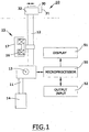
FIG. 1 is a schematic view of a preferred embodiment of our improved tonometer, which is suitable for practicing our inventive eye examinations. -
FIG. 2 is a schematic diagram of a portion of the tonometer ofFIG. 1 involving a prism applanating an eye, a light source, a detector, a microprocessor, and an output. -
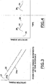
FIGS. 3-7 are schematic graphs of detector signals produced pursuant to our inventive eye examinations. - Our eye examining method requires an instrument that can produce a signal representing intra ocular pressure (IOP) of an eye being examined. Such instruments are normally called tonometers, but our instrument and the ways it can be used produces information going beyond what can be expected of precious tonometers. Several variations of tonometers suitable for our purposes are described in our previous patents and applications. A presently preferred embodiment of such a
tonometer 10 is schematically represented inFIGS. 1 and2 .Tonometer 10 preferably includes anactuator 15 pressing aprism 30 with a variable and determinable force against a cornea of an eye while alight source 20 directs light to reflect from anapplanation surface 31 ofprism 30 to adetector 25. In response to received light,detector 25 produces a detected light signal that is electrical in form and is sent to and analyzed bymicroprocessor 50 which in turn controlsactuator 15 for varying the force ofprism 30 pressing against theeye 40 and for varying the energization oflight source 20.Microprocessor 50 also preferably drives adisplay 51 and preferably communicates with output andinput devices 52. - The essential components of
tonometer 10 includemicroprocessor 50,prism 30, some form ofactuator 15, a light orradiation source 20, and a transducer ordetector 25 receiving light or radiation reflected fromapplanation surface 31 and sending a corresponding electric signal tomicroprocessor 50. The precise working relationships among these essential components can be varied considerably, however, and the schematic illustrations ofFIGS. 1 and2 show only a presently preferred embodiment. - Prism 30 is preferably replaceable and disposable so that it can be removed from
prism holder 32 after each examination and replaced with a fresh prism. This ensures that infectious agents, including the possibility of prions, are not transmitted from one pair of eyes to another. -
Prism holder 32 is preferably mounted onarm 12, which is arranged to rotate or turn slightly aroundpivot 13. Since only a few millimeters of movement back and forth ofprism 30 is required, as indicated by the double headed arrow, the rotational turning ofarm 12 is slight. - A
counter balance 14 arranged onarm 11 is arranged with a suitable moment arm relative topivot 13 to returnprism holder arm 12 to a base position. Proper arrangement and balancing ofarms pivot 13 can eliminate the need for any return spring, and can enableinstrument 10 to operate in different orientations. - Actuator 15 can be any of a variety of motors and other preferably electromagnetic prime movers. The preferred actuator schematically illustrated in
FIG. 1 includes acoil 16 that is moveable relative to apermanent magnet 17, depending on the power supplied tocoil 16. The relativelylighter coil 16 is preferably fixed toarm 12, and the relatively heavierpermanent magnet 17 is preferably fixed to a body ofinstrument 10, because this reduces the rotating mass. It might also be possible to arrangepermanent magnet 17 orcoil 16 in the position ofcounter balance 14 to further reduce the rotational mass. Many other possibilities exist but for sake of conciseness and simplicity have not been illustrated. - Internal wiring within
instrument 10 preferably connects a power supply (not shown) withmicroprocessor 50, which powersactuator 15,light source 20, andlight detector 25.Microprocessor 50 preferably drivesdisplay 51 to display information directly to an instrument operator, andmicroprocessor 50 preferably has connections enabling it to receive and output information to and from other devices such as computer keyboards andnumber pads 52. - The light emitted by
source 20 is preferably in a visible red region of the electromagnetic spectrum, but other colors of visible light are also possible, as is radiation energy at infra red or microwave frequencies. For simplicity, all of these possible different radiation frequencies are characterized as "light" within this application. As is well known, use of electromagnetic radiation at different frequencies can require angular adjustments so that light withinprism 30 that is internally incident onapplanation surface 31 is internally reflected todetector 25 except for a portion of the light that transmits intoeye 40 through an applanation region of contact withprism surface 31. Of course, anyradiation entering eye 40 must not cause injury. - Prism 30 is preferably molded of resin material to have a low enough manufacturing cost to be affordably disposable. Much more information on preferred characteristics of
prism 30 is available in ourUS Patent 6,179,779 and our pending application09/811,709 microprocessor 50 is preferably programmed to require thatprism 30 be replaced after being used for examining a pair of eyes. This is intended to prevent the tonometer prism from transporting infectious agents from the eyes of one person to the eyes of another. - Experiments and clinical experience with a working prototype of a tonometer instrument such as shown in
Figures 1 and2 has led to a simpler way of measuring a conventional diastolic intra ocular pressure (IOP). Our previous patents and applications recommended determining IOP from prism pressing force required to change between a reference applanation area (with a corresponding reference signal) and a measurement applanation area (with a corresponding measurement signal). We have now found that it is not necessary to use predetermined reference and measurement areas and corresponding signals to determine IOP. - Our new method preferably begins with a preliminary value of a detected light signal that the tonometer microprocessor is programmed to recognize. The preliminary value is preferably based upon preliminary contact of the prism applanation surface with a cornea at either bare contact pressure arising from surface tension of tears in the eye, or from a preferably very light predetermined prism pressing force.
- The tonometer can be programmed to recognize that the preliminary value has occurred by noting the sodden reduction in the detected signal that occurs when the prism contacts the eye. Before this happens, all the light incident on
prism applanation surface 31 is internally reflected, but whensurface 31 contacts a cornea, a portion of the incident light is transmitted into the eye in the area of contact so that the detected light signal diminishes noticeably. The preliminary value signal can vary from eye to eye, as explained below, but can also serve as a starting point for an IOP determination. - Then instead of proceeding from the preliminary value to a measurement value, we proceed from the preliminary value through a range of values extending from the preliminary value. Any value at the end of the range extending from the preliminary value is not a fixed value, but is based only on distance from the preliminary value. To accomplish this, we program the microprocessor to operate
actuator 15 to pressprism applanation surface 31 against the cornea with increasing force applied during a time interval to change the detected light signal from the preliminary value through a range of values extending from the preliminary value. In doing this,microprocessor 50 preferably energizesactuator 15 to apply increasing prism force in predetermined increments that are applied in predetermined brief time intervals so that the detectedlight signal 26 varies in a step wise, sloped configuration as graphically illustrated inFigure 3 . Prism force changes and time intervals can also be continuous or analog, rather than being broken into the preferred increments. Also, prism force changes with respect to time are preferably linear, rather than non-linear, to simplify slope determinations. -
Signal 26 then provides several ways of determining IOP. One way is to proceed with increasing prism pressure force for a predetermined number of increments or for a predetermined time interval resulting in a predetermined increase in prism pressing force above the preliminary value. We thenprogram microprocessor 50 to determine IOP from the signal change reached at the end value of the predetermined range of prism force change values. By a similar method, the force change values can be continued until the detectedlight signal 26 reaches a predetermined departure from the preliminary value, withmicroprocessor 50 determining IOP from the total pressure force required to reach the end signal value. Such an end signal value differs from the previously suggested measurement signal value by being related to thepreliminary signal value 27 rather than being an absolute or independent value. - Another way that
microprocessor 50 can determine IOP from detectedlight signal 26 is by measuring or detecting the slope assignal 26 changes over a time or force interval. We have found that signal slope alone is enough formicroprocessor 50 to make an accurate determination of IOP. We have also found that detected signal slope tends to roll off at higher prism forces, so we prefer using a linear mid-region or lower force region of detectedsignal 26 for an IOP determination. - From an ophthalmologically known relation between IOP and force used in applanating a corneal area we have been able to apply linear, logarithmic, and logistic regression analyses to calculate IOP from the signals produced by
instrument 10. In these analyses we have used the slope of the detected signal as changes in prism force change corneal applanation area and cause a corresponding change in signal value. Especially logistic regression analysis, which allows us to consider several variables at a time, has been useful in making force-to-signal-to-IOP calculations. We have also corroborated these results by manometric comparisons and Goldman tonometer readings. -
Microprocessor 50 is preferably not programmed to make sophisticated mathematical calculations itself. We prefer instead that signal analysis be done separate frommicroprocessor 50, which is then programmed or loaded with a look up table from which it can determine IOP based on signal values. In doing this,microprocessor 50 can be programmed to average an IOP determination made by different methods. - These IOP determining methods can also be combined or used in conjunction so that one determination corroborates another. Moreover, elapsed time required to reach an end value can serve as another corroborator of an IOP determination. All the IOP determining methods can be combined in a single instrument that determines IOP according to each method and corroborates by comparing elapsed time, force change and electrical signal change. Any differences in the IOP determinations can be averaged out, unless differences are unusually large, in which case the microprocessor can be programmed to repeat the measurement. In a similar way, if elapsed time casts doubt on the accuracy of an IOP determination, the examination can be repeated.
- These methods of IOP determination, besides being simple, accurate and fast, have another important advantage. By monitoring signal change relative to a
predetermined value 27 that is not fixed but is related to each eye being examined, these IOP determining methods automatically take into account variations in corneal curvature and thickness. Our previous IOP determining suggestions envisioned separate measurements of corneal curvature and corneal thickness and input of such measurements to adjust IOP determinations. This is no longer necessary with our present IOP determining methods, because thepreliminary signal value 27 is not a fixed value but is allowed to vary with each eye being examined. - This variation is schematically illustrated in
Figure 3 by the difference between preliminary value signals 27 and 27a, and the corresponding difference between detectedsignals preliminary signal value 27 can be seen as a typical signal produced by contact of the tonometer prism with the cornea of a normal eye having a normally curved or arched cornea and a normal cornea thickness.Preliminary value signal 27a then indicates a preliminary contact signal from a cornea that is flatter or less arched than normal or a cornea that is thinner than normal. The value ofpreliminary signal 27a being less than the value ofpreliminary signal 27 indicates that preliminary prism contact with the thinner or flatter cornea has applanated a larger area. It would also be possible, but is omitted for the sake of simplicity, to show another preliminary value signal larger thansignal 27, indicating preliminary contact with a cornea that is more arched than normal or is thicker than normal, resulting in applanation of a smaller area. - The ophthalmological literature indicates that every 50-micrometer variation in corneal thickness produces a 1.5mm variation in measured IOP. This variation will automatically appear in
preliminary value signal 27 to adjust the starting point for a predetermined range of values. Similar indications are available in the ophthalmological literature for the effects of differences in arching or curvature of the cornea. These two translate into differences in measured IOP, which are automatically compensated for bypreliminary signal value 27. - The variations in
preliminary signal 27 due to corneal characteristics such as curvature and thickness do not matter in our present method of determining IOP,- because change in detectedlight signal - We have also found that our tonometer instrument detects systolic pulses during eye examinations. Goldman tonometers, which are ubiquitous in opthalmological clinics, cannot make an IOP reading during a systolic pulse. Our instrument, in contrast, produces a detected light signal during both a diastolic phase and a systolic phase. This has led to several new ways of determining IOP, one of which is schematically graphed in
Figure 4 . - The process illustrated in
Figure 4 occurs after making a determination of diastolic IOP. For doing this,microprocessor 50 is preferably programmable to allow an operator to secure a reading only of diastolic IOP. Ocular pulse signals occurring during a systolic phase are then ignored bymicroprocessor 50 in making an IOP determination.Microprocessor 50 can also be programmed to proceed in several ways to determine a diastolic lOP while also taking into account the detected signal departure from adiastolic phase 26 during a systolic pulse. - For the method illustrated in
Figure 4 ,microprocessor 50 is programmed to operateactuator 15 to holdprism 30 against a cornea with a predetermined force for a long enough duration for twosystolic pulses 28 to occur. These are illustrated inFigure 4 as saw-tooth shaped increases in the otherwise flatdiastolic signal 26. The height of systolic pulse signals 28 abovediastolic signal 26 indicates ocular pulse pressure, and this is preferably used as an ingredient in an IOP determination. The fact that systolic pulse signals 28 are larger or higher than thediastolic phase signal 26 is because a systolic pulse slightly hardens the eye being examined, which reduces the area applanated by thetonometer prism 30 and increases the detected light signal. - The eye is subject not only to the IOP occurring in a diastolic phase, but also to the increased IOP that occurs during a systolic pulse when a bolus of blood flows into the eye. An IOP determination based only on a diastolic phase measurement therefore does not indicate the true pressure experienced by the eye over time. For example, a diastolic pressure might be 20 mm of mercury, while systolic pulse pressures reach 26 mm of mercury. A true IOP reading for all the pressure experienced by the eye over time should then include the systolic pulse pressures as a factor increasing the IOP over the diastolic phase pressure.
-
Broken line 29, as illustrated inFigure 4 , indicates an average, weighted average, or mean IOP determined not only fromdiastolic phase signal 26, but the increased height of ocular pulse signals 28, and a pulse rate.Microprocessor 50 is preferably capable of measuring time intervals and of calculating a pulse rate from the time elapsed between a pair of ocular pulse-pressure signals 28.Microprocessor 50 then preferably determines a mean or average IOP having a value higher than a diastolic phase measurement, based on the height and frequency of systolic pulse pressures. The systolic or ocular pulse pressure is calculated in a manner similar to the calculation of the diastolic IOP. The ocular pulse pressure can also be calculated as a percentage of the deviation from the diastolic phase IOP. Various regression analyses can be applied to these calculations, which can be corroborated manometrically. -
Microprocessor 50 can also be programmed to determine only a systolic IOP, which can be done by ignoringdiastolic signal phase 26. For most purposes, though, an average, weighted average, or mean IOP determination based on both diastolic and systolic phase signals is preferred. - The ability of our
instrument 10 to produce usable systolic pulse signals 28 can also be used to determine ocular blood flow. This is preferably determined from the height of systolic pulse signals 28 abovediastolic base line 26. The ophthalmological literature includes suggestions for calculating ocular blood flow from ocular pulse pressure by using a Friedenwald equation or one of the suggested modifications of the Friedenwald equation. Most of these suggestions focus on the height ofsignal 28 above adiastolic base line 26, as we prefer. Some suggestions have also focused on a leading edge ofsignal 28, and at least one proposal, which we have not adopted, suggests that the area under thesignal 28 above thediastolic baseline 26 be considered. The various forms of regression analysis can also be applied to ocular blood flow calculations, and these can be corroborated by clinical experience. Whatever calculations are used, the results are preferably translated into a look up table programmed intomicroprocessor 50 for use in outputting ocular blood flow information. - Another measurement that becomes possible from the availability of ocular pulse-pressure signals 28 is a tonography measure of the effectiveness of the trabecular meshwork of the eye being examined. We prefer determining this from the downward or trailing
slope 24 of the ocular pulse-pressure signal 28 as it returns from a peak pressure back to thediastolic base line 26. Generally, a steeperdownward slope 24 indicates an effective trabecular meshwork that quickly returns from an elevated ocular pulse pressure back to a diastolic level. Conversely, a more gradual and extendeddownward slope 24 indicates a trabecular meshwork that is more impaired and recovers more slowly from a systolic pulse pressure. - Methods of calculating tonography measures from applanation signals are also available in the ophthalmological literature. These generally agree that down
slope 24 is a key ingredient for tonography calculations. Like the IOP and ocular blood flow calculations, tonography measures can be refined by regression analyses and can be corroborated by clinical experience and by other measures; they are preferably translated into a look up table programmed into microprocessor 50., - The availability of a tonography measure, along with an ocular pulse pressure measure and an ocular blood flow determination gives a clinician considerably more information than has been available from tonometers. This additional information is valuable for both diagnostic and treatment purposes. Knowing the value of systolic pulse pressures and average or mean IOP gives information that is helpful in setting the aggressiveness of treatments used to reduce IOP. It can also help to determine whether to treat with drugs aimed at improving the effectiveness of the trabecular meshwork or whether to treat with drugs aimed at slowing down the production of ocular fluid. For example, using
tonometer 10 to produce both an IOP determination and a tonography determination can affect a treatment method for an eye being examined. If the IOP determination is high enough to warrant treatment and the tonography determination is normal, then a clinician would treat the eye with a drug aimed at reducing production of aqueous fluid. On the other hand, if the IOP determination is high enough to warrant treatment and the tonography determination is subnormal, meaning that the trabecular meshwork of the eye is performing at a rate less than normal in removing aqueous fluid from the eye, then a clinician would treat the eye with a drug aimed at improving performance of the trabecular meshwork. - Knowing a measure of ocular blood flow can be relevant to these choices because some drugs can reduce ocular blood flow as a side effect. This must be guarded against so that ocular blood flow is not reduced enough to impair the health of the optic nerve and other eye components. Some drugs used in glaucoma treatment are either known or suspected of reducing ocular blood flow as a side affect, and having an ocular blood flow determination readily available can be used to avoid such drugs in a treatment aimed at reducing IOP.
- Some drugs are also known to improve blood circulation generally, and these can be used if an ocular blood flow determination indicates that ocular blood flow of an eye being examined could advantageously be increased. This is the case with normal pressure glaucoma that impairs an optic nerve by reduction of ocular blood flow while an IOP determination remains normal. A
clinician having tonometer 10 to make determinations of both IOP and ocular blood flow can diagnose that deterioration of an optic nerve is caused by subnormal ocular blood flow, without any increase in IOP. The appropriate treatment based on the low ocular blood flow determination provided bytonometer 10 would then be aimed at improving ocular blood flow, rather than reducing IOP. Drugs now exist. that improve blood flow generally, and these can be tried and the results monitored by rechecking the eye for both IOP and ocular blood flow. Drugs may also be developed that will aim especially at increasing ocular blood flow while minimally affecting blood flow elsewhere. - Since ocular blood flow determinations have not previously been readily available to clinicians treating eyes for glaucoma, the effect of an ocular blood flow determination on eye treatment strategies has not been generally known. The ability of
instrument 10 to provide such ocular blood flow information has many uses including monitoring an eye under treatment to be sure that the treated eye is not suffering from reduced ocular blood flow, which would call for a change in drugs being used in treatment. Having an ocular blood flow determination available frominstrument 10 can also be beneficial in verifying that a drug aimed at increasing ocular blood flow in an eye experiencing normal pressure glaucoma has actually improved ocular blood flow. Knowing a tonography measure of the effectiveness of the eye's trabecular meshwork can also help monitor treatment determinations. For example, this can be used to determine the effectiveness of drugs intended to improve the working of the trabecular meshwork. -
Figure 5 illustrates the possibility of producing in a shingle examination excursion a signal that includes apreliminary value 27, adiastolic phase 26, and a systolic phase that includesocular pulses 28. Such a signal would preferably extend for long enough to include twoocular pulses 28 so thatmicroprocessor 50 can calculate a pulse rate. Of course, it is possible for such a signal to extend for a longer time, but this adds to the time that the prism is pressed against a patient's eye. A typical time needed to complete an examination excursion for diastolic purposes only is from 0.5 to 1.0 seconds. This would have to be extended somewhat to insure that twosystolic pulses 28 occurred for pulse rate determination. - The signals shown in
Figure 5 can be used to determine an average or meanIOP 29 as previously described, along with ocular pulse signals 28. Althoughdiastolic baseline 26 is sloped because of the signal being generated while prism pressure increases over time, all the information necessary for determining IOP in the ways described. above is available. An adjustment is needed formicroprocessor 50 to take into account the sloping nature of thebaseline signal 26 and the corresponding sloping nature of ocular pulse signals 28. Once the slopes are taken into account, all the necessary calculations for diastolic, systolic, and average or mean IOP can be calculated, along with ocular blood flow and a tonography measure. -
Figure 6 illustrates the possibility of producing a signal during increasing prism pressure assignal 26 slopes downward, followed by diminishing prism pressure assignal 26 slopes back upward. Such a reversing signal can also extend for long enough to include at least twoocular pulses 28 from which pulse rate can be determined. Again, after taking into account the slopes caused by prism force changes over time, a signal such as illustrated inFigure 6 can be used to make all the determinations described above. -
Figure 7 schematically illustrates another way of determining a tonography measure by usingtonometer 10. Beginning withpreliminary signal value 27,microprocessor 50 is programmed to increase prism pressure force in one of the previously described ways to produce signal 36 (from which any systolic pulses have been eliminated) to make a preliminary determination of diastolic IOP. Prism force is then increased to producesignal 37, and prism force is sustained at that level for a predetermined interval. The prism force level for producingsignal 37 is sufficient to raise the IOP of the eye to a level above the IOP determination made during the excursion-producingsignal 36. During the interval that prism pressure force is elevated, as represented bysignal 37, the eye that is subjected to the extra pressure attempts to accommodate to return its IOP to normal. The predetermined interval allowed for this is preferably in the range of a minute or two. Then prism pressure force is released, as represented bysignal 38 and a new or subsequent IOP is determined as represented bysignal 39 formed by increasing prism pressure from apreliminary value 27b. - The prism pressure force used to elevate the IOP to test the accommodating ability of the eye's trabecular meshwork is preferably sufficient to depress an ocular pulse signal during the predetermined interval that the prism force is applied. This results in the accommodation attempted by the trabecular meshwork to arise from the elevated IOP caused by the prism force as distinct from periodic accommodations following systolic pulses.
- When elevated prism force is removed at the end of
signal 37, the IOP of the previously pressurized eye reduces for a brief interval until the eye re-accommodates. During this interval a subsequent determination of diastolic IOP is made as represented bysignal 39 showing that the IOP is reduced, and the eye has become temporarily softer. The difference between the higher IOP determined fromsignal 36 and the lower IOP determined fromsignal 39 gives a measure of the effectiveness of the trabecular meshwork of the eye. The healthier the eye, the greater will be the amount that the subsequent IOP is reduced from the preceding IOP. - This procedure is analogous to a known way of determining tonography by measuring IOP of an eye, and then while a patient is lying down, placing a weight on a patient's eye for an interval after which the IOP is again measured. Such a method is cumbersome and time consuming, since the patient has to lie down, and a weight has to be placed on the eye and then removed in between IOP determinations. By the method illustrated in
Figure 7 ,instrument 10 can make such a process much more efficient without requiring any weight and without requiring the patient to lie down.
Claims (6)
- A method of measuring intraocular pressure of an eye, the methods using a tonometer (10) having an actuator (15) that presses a prism (30) with a variable and determinable electromagnetic force against a cornea of the eye being examined while a detector (25) receives reflected light representing a varying size of an applanated area of the cornea and produces a detected light signal delivered to a programmed microprocessor (50), the method begins with initial contact of the prism (30) with the cornea producing a preliminary value of the detected light signal, applying an electromagnetic force to press the prism (30) against the eye after the initial contact to enlarge the applanated area, determining the electromagnetic force applied to the prism (30) and the respective detected light signal produced, the method being characterized by:using surface tension of tears in the eye being examined to supply a force pulling the freely movable applanation surface (31) against the eye to produce the preliminary value whose size is a function of thickness and curvature of the cornea of the eye being examined;determining IOP by proceeding with increasing prism pressure force for a predetermined number of increments or for a predetermined time interval resulting in a predetermined increase in prism pressing force above the preliminary value, from which microprocessor (50) is programmed to determine IOP from the signal change reached at the end value of the predetermined range of prism force change values; ordetermining IOP from force change values that are continued until the detected light signal reaches a predetermined departure from the preliminary value, from which the microprocessor determines IOP from the total pressure force required to reach the end signal value.
- A method according to claim 1 including pressing the applanation surface (31) against the cornea long enough for the microprocessor (50) to detect from the detected light signal at least two systolic pulses departing from the determined intraocular pressure, and the microprocessor (50) being programmed to determine from applanated area end value signal an average or mean intraocular pressure.
- A method according to claim 1 or claim 2 including determining an ocular pulse pressure from the departures from a diastolic phase of the applanated area end value signal during the systolic pulses.
- A method according to any one of claims 1-3 including determining ocular blood flow based on the applanated area end value signal departures from a diastolic phase occurring during the systolic pulses and based on time intervals between the systolic pulses.
- A method according to any one of claims 1-4 including determining the intraocular pressure as a mean intraocular pressure and determining an ocular pulse pressure based on the applanated area end value signal departures from the mean intraocular pressure during the systolic pulses.
- A tonometer comprising:a prism (30) having an applanation surface (31) arranged to be pressed against a cornea of an eye being examined, the prism (30) being supported on a rotationally moveable arm (12);the electromagnetic actuator (15) including a permanent magnet and a coil, one of which is mounted on the arm supporting the prism (30) and the other of which is mounted in a fixed position;a counterbalance applying a rotational moment arm (12) to return the movable arm to a starting position without requiring a return spring;a detector (25) receiving rejected light indicating a varying size of an area of the cornea applanated by the prism (30); anda microprocessor (50) arranged to receive a detected light signal from the detector (25) and being programmed to determine an intraocular pressure of the eye according to the method of claim 1.
Applications Claiming Priority (3)
| Application Number | Priority Date | Filing Date | Title |
|---|---|---|---|
| US178987 | 2002-06-25 | ||
| US10/178,987 US7473231B2 (en) | 2002-06-25 | 2002-06-25 | Method and apparatus for examining an eye |
| PCT/US2003/019891 WO2004000162A2 (en) | 2002-06-25 | 2003-06-24 | Method and apparatus for examining an eye |
Publications (3)
| Publication Number | Publication Date |
|---|---|
| EP1521546A2 EP1521546A2 (en) | 2005-04-13 |
| EP1521546A4 EP1521546A4 (en) | 2009-08-26 |
| EP1521546B1 true EP1521546B1 (en) | 2016-08-10 |
Family
ID=29734832
Family Applications (1)
| Application Number | Title | Priority Date | Filing Date |
|---|---|---|---|
| EP03761293.4A Expired - Lifetime EP1521546B1 (en) | 2002-06-25 | 2003-06-24 | Method and apparatus for examining an eye |
Country Status (5)
| Country | Link |
|---|---|
| US (3) | US7473231B2 (en) |
| EP (1) | EP1521546B1 (en) |
| AU (1) | AU2003265251B2 (en) |
| CA (1) | CA2490912C (en) |
| WO (1) | WO2004000162A2 (en) |
Families Citing this family (18)
| Publication number | Priority date | Publication date | Assignee | Title |
|---|---|---|---|---|
| US7473231B2 (en) * | 2002-06-25 | 2009-01-06 | Francis Y. Falck | Method and apparatus for examining an eye |
| US7097637B2 (en) * | 2003-08-27 | 2006-08-29 | C. R. Bard, Inc. | Safety needle with positive flush |
| US20070197932A1 (en) * | 2006-02-17 | 2007-08-23 | Feke Gilbert T | Non-invasive methods for evaluating retinal affecting neurodegenerative diseases |
| CN101190122B (en) * | 2006-11-30 | 2012-01-11 | 蒂奥拉特公司 | Method for measuring intraocular pressure |
| US8070679B2 (en) * | 2007-07-23 | 2011-12-06 | The Board Of Trustees Of The University Of Illinois | Accurate determination of intraocular pressure and characterization of mechanical properties of the cornea |
| US20090103047A1 (en) * | 2007-10-23 | 2009-04-23 | Falck Medical, Inc. | Tonometer Using Camera and Ambient Light |
| FR2924913B1 (en) * | 2007-12-18 | 2010-02-05 | Alain Telandro | SYSTEM FOR MEASURING OCULAR PRESSURE |
| US20110087086A1 (en) * | 2009-10-12 | 2011-04-14 | Falck Medical, Inc. | Method of Estimating Ocular Perfusion Pressure |
| US9320430B2 (en) | 2010-03-31 | 2016-04-26 | Reichert, Inc. | Ophthalmic diagnostic instrument and method |
| US9232892B2 (en) | 2010-11-03 | 2016-01-12 | Lighttouch, Llc | Applanation tonometer and method for measuring the intraocular pressure of the eye |
| US9585578B2 (en) | 2011-12-02 | 2017-03-07 | Third Eye Diagnostics, Inc. | Devices and methods for noninvasive measurement of intracranial pressure |
| US9078612B2 (en) | 2011-12-02 | 2015-07-14 | Third Eye Diagnostics, Inc. | Devices and methods for noninvasive measurement of intracranial pressure |
| US9357912B2 (en) * | 2013-09-09 | 2016-06-07 | Yan Zhang | Apparatus and method for characterizing biomechanical properties of eye tissue |
| PL227692B1 (en) * | 2014-01-31 | 2018-01-31 | Nogal Piotr Twoje Oczy | Non-invasive, contact, compression-refraction tonometer of the eye postremal chamber and/or the vitreous body chamber |
| US20150313573A1 (en) * | 2014-05-02 | 2015-11-05 | Ohio State Innovation Foundation | Ophthalmic elastography |
| US9828738B2 (en) * | 2014-12-19 | 2017-11-28 | Beacon Athletics, Inc. | Tamping tool |
| KR102801310B1 (en) * | 2018-08-09 | 2025-04-30 | 밸런스 오프탈믹스, 인크. | Apparatus and methods to adjust ocular blood flow |
| JP6707239B1 (en) * | 2019-03-13 | 2020-06-10 | 株式会社中京メディカル | Keratoconus determination device and program |
Family Cites Families (28)
| Publication number | Priority date | Publication date | Assignee | Title |
|---|---|---|---|---|
| US3452589A (en) * | 1966-04-22 | 1969-07-01 | Pennsylvania Lions Sight Conse | Apparatus for measuring stress-strain characteristics |
| US3585849A (en) * | 1968-10-09 | 1971-06-22 | American Optical Corp | Method and apparatus for measuring intraocular pressure |
| US3572100A (en) * | 1969-05-28 | 1971-03-23 | American Optical Corp | Synchronizer for a tonometer |
| US3706304A (en) | 1970-02-19 | 1972-12-19 | Hampson A Sisler | Optical ophthalmodynamometer |
| GB1360603A (en) * | 1970-07-01 | 1974-07-17 | Clarke Ltd Clement | Applanation tonometers |
| HU172843B (en) * | 1975-11-17 | 1978-12-28 | Medicor Muevek | Device for ophthalmic particularly glaucoma screening test |
| US4209021A (en) * | 1977-12-22 | 1980-06-24 | J. D. Moller Optische Werke Gmbh | Apparatus for generating and measurement of defined forces for medical appliances |
| US4281662A (en) | 1979-09-05 | 1981-08-04 | Allan Brent | Ocular testing device |
| US4572199A (en) * | 1982-12-27 | 1986-02-25 | University Of New Hampshire | System to determine arterial occlusion and other maladies |
| US5203331A (en) * | 1989-07-17 | 1993-04-20 | Haag-Streit Ag | Applanation tonometer |
| DE3931630A1 (en) * | 1989-09-22 | 1991-05-08 | Datron Electronic Gmbh | METHOD AND DEVICE FOR DETERMINING THE INTERNAL PRESSURE OR THE LIKE |
| US4987899A (en) * | 1989-10-17 | 1991-01-29 | Brown Alan W | Applanation tonometer |
| US4948062A (en) * | 1989-10-31 | 1990-08-14 | Mahar Paul J | Sterile film dispenser for applanating tonometer |
| US5140990A (en) * | 1990-09-06 | 1992-08-25 | Spacelabs, Inc. | Method of measuring blood pressure with a photoplethysmograph |
| US5070875A (en) * | 1990-11-19 | 1991-12-10 | Falcken, Inc. | Applanation tonometer using light reflection to determine applanation area size |
| US5355884A (en) * | 1992-10-30 | 1994-10-18 | Bennett Emeric S | Applanation tonometer for measuring intraocular pressure |
| US5363155A (en) * | 1993-02-18 | 1994-11-08 | Ehud Urinowski | Eye examination apparatus and accessory therefor |
| US5810005A (en) | 1993-08-04 | 1998-09-22 | Dublin, Jr.; Wilbur L. | Apparatus and method for monitoring intraocular and blood pressure by non-contact contour measurement |
| US5474066A (en) * | 1994-01-31 | 1995-12-12 | Leica Inc. | Non-contact tonometer |
| GB2295460B (en) * | 1994-11-26 | 1998-04-29 | O B F Labs | Improvements in and relating to a pneumatic pressure probe |
| US6544193B2 (en) * | 1996-09-04 | 2003-04-08 | Marcio Marc Abreu | Noninvasive measurement of chemical substances |
| US6120460A (en) * | 1996-09-04 | 2000-09-19 | Abreu; Marcio Marc | Method and apparatus for signal acquisition, processing and transmission for evaluation of bodily functions |
| US5830139A (en) * | 1996-09-04 | 1998-11-03 | Abreu; Marcio M. | Tonometer system for measuring intraocular pressure by applanation and/or indentation |
| GB9717894D0 (en) * | 1997-08-22 | 1997-10-29 | Clement Clarke Int | Applanating tonmeters |
| US6736778B2 (en) * | 1997-12-22 | 2004-05-18 | Francis Y. Falck, Jr. | Replaceable prism for applanation tonometer |
| US6179779B1 (en) * | 1997-12-22 | 2001-01-30 | Ffhk Development Company Llc | Replaceable prism system for applanation tonometer |
| US7473231B2 (en) * | 2002-06-25 | 2009-01-06 | Francis Y. Falck | Method and apparatus for examining an eye |
| US20050020896A1 (en) * | 2003-07-24 | 2005-01-27 | Fuller Terry A. | Apparatus and method of intraocular pressure determination |
-
2002
- 2002-06-25 US US10/178,987 patent/US7473231B2/en not_active Expired - Lifetime
-
2003
- 2003-06-24 WO PCT/US2003/019891 patent/WO2004000162A2/en not_active Ceased
- 2003-06-24 AU AU2003265251A patent/AU2003265251B2/en not_active Expired
- 2003-06-24 CA CA2490912A patent/CA2490912C/en not_active Expired - Lifetime
- 2003-06-24 EP EP03761293.4A patent/EP1521546B1/en not_active Expired - Lifetime
-
2006
- 2006-05-30 US US11/420,971 patent/US20060235313A1/en not_active Abandoned
-
2007
- 2007-04-05 US US11/697,006 patent/US20070173713A1/en not_active Abandoned
Also Published As
| Publication number | Publication date |
|---|---|
| EP1521546A4 (en) | 2009-08-26 |
| US20030236470A1 (en) | 2003-12-25 |
| CA2490912C (en) | 2015-03-31 |
| WO2004000162A3 (en) | 2004-04-15 |
| US7473231B2 (en) | 2009-01-06 |
| CA2490912A1 (en) | 2003-12-31 |
| EP1521546A2 (en) | 2005-04-13 |
| US20060235313A1 (en) | 2006-10-19 |
| US20070173713A1 (en) | 2007-07-26 |
| WO2004000162A2 (en) | 2003-12-31 |
| AU2003265251A1 (en) | 2004-01-06 |
| AU2003265251B2 (en) | 2009-01-22 |
Similar Documents
| Publication | Publication Date | Title |
|---|---|---|
| US20070173713A1 (en) | Method and Apparatus for Determining Intra Ocular Pressure of an Eye | |
| US5830139A (en) | Tonometer system for measuring intraocular pressure by applanation and/or indentation | |
| US20030187343A1 (en) | Force feedback tonometer | |
| EP2182836A1 (en) | Optical apparatus for measuring a physiological property of a body part and method therefore | |
| CN110430800A (en) | Method for determining vascular collapse in or at the eye, and clamping device and retinal blood pressure measurement assembly | |
| KR101348942B1 (en) | Intraocular pressure measuring device and method for calculating intraocular pressure | |
| US20050030473A1 (en) | Apparatus and method for determining intraocular pressure and corneal thickness | |
| JP4562970B2 (en) | Method and apparatus for determining intraocular pressure by measuring changes in frequency characteristics | |
| EP2308369B1 (en) | Method of estimating ocular perfusion pressure | |
| WO2018031386A1 (en) | Portable devices for monitoring eye diseases and methods thereof | |
| JP2001500419A (en) | Non-contact tonometer with off-axis fluid pulse system | |
| FI131841B1 (en) | Air pulse tonometers | |
| CN105342551A (en) | Instrument for detecting cornea biomechanics and application method of instrument | |
| FI131741B1 (en) | Tonometer for measuring intraocular pressure with pulsating air | |
| US20240188823A1 (en) | Intraocular pressure detecting device and detecing method thereof | |
| AU758525B2 (en) | A tonometer system for measuring intraocular pressure by applanation and/or indentation | |
| JP2026514854A (en) | Tonometer and related methods for measuring the characteristics of the eye | |
| WO2026037979A1 (en) | Tonometers for measuring intraocular pressure of eye using air pulse | |
| WO2026099539A1 (en) | Air pulse tonometer for measuring intraocular pressure of an eye | |
| Maharana et al. | Corneal Biomechanics: Ocular Response Analyzer and Dynamic Scheimpflug Imaging | |
| MXPA99002157A (en) | A tonometer system for measuring intraocular pressure by applanation and/or indentation |
Legal Events
| Date | Code | Title | Description |
|---|---|---|---|
| PUAI | Public reference made under article 153(3) epc to a published international application that has entered the european phase |
Free format text: ORIGINAL CODE: 0009012 |
|
| 17P | Request for examination filed |
Effective date: 20041223 |
|
| AK | Designated contracting states |
Kind code of ref document: A2 Designated state(s): AT BE BG CH CY CZ DE DK EE ES FI FR GB GR HU IE IT LI LU MC NL PT RO SE SI SK TR |
|
| AX | Request for extension of the european patent |
Extension state: AL LT LV MK |
|
| DAX | Request for extension of the european patent (deleted) | ||
| A4 | Supplementary search report drawn up and despatched |
Effective date: 20090729 |
|
| 17Q | First examination report despatched |
Effective date: 20100324 |
|
| GRAP | Despatch of communication of intention to grant a patent |
Free format text: ORIGINAL CODE: EPIDOSNIGR1 |
|
| INTG | Intention to grant announced |
Effective date: 20160121 |
|
| GRAS | Grant fee paid |
Free format text: ORIGINAL CODE: EPIDOSNIGR3 |
|
| GRAA | (expected) grant |
Free format text: ORIGINAL CODE: 0009210 |
|
| AK | Designated contracting states |
Kind code of ref document: B1 Designated state(s): AT BE BG CH CY CZ DE DK EE ES FI FR GB GR HU IE IT LI LU MC NL PT RO SE SI SK TR |
|
| REG | Reference to a national code |
Ref country code: GB Ref legal event code: FG4D |
|
| REG | Reference to a national code |
Ref country code: CH Ref legal event code: EP Ref country code: AT Ref legal event code: REF Ref document number: 818181 Country of ref document: AT Kind code of ref document: T Effective date: 20160815 |
|
| REG | Reference to a national code |
Ref country code: IE Ref legal event code: FG4D |
|
| REG | Reference to a national code |
Ref country code: DE Ref legal event code: R096 Ref document number: 60349239 Country of ref document: DE |
|
| REG | Reference to a national code |
Ref country code: NL Ref legal event code: MP Effective date: 20160810 |
|
| REG | Reference to a national code |
Ref country code: AT Ref legal event code: MK05 Ref document number: 818181 Country of ref document: AT Kind code of ref document: T Effective date: 20160810 |
|
| PG25 | Lapsed in a contracting state [announced via postgrant information from national office to epo] |
Ref country code: NL Free format text: LAPSE BECAUSE OF FAILURE TO SUBMIT A TRANSLATION OF THE DESCRIPTION OR TO PAY THE FEE WITHIN THE PRESCRIBED TIME-LIMIT Effective date: 20160810 Ref country code: FI Free format text: LAPSE BECAUSE OF FAILURE TO SUBMIT A TRANSLATION OF THE DESCRIPTION OR TO PAY THE FEE WITHIN THE PRESCRIBED TIME-LIMIT Effective date: 20160810 Ref country code: IT Free format text: LAPSE BECAUSE OF FAILURE TO SUBMIT A TRANSLATION OF THE DESCRIPTION OR TO PAY THE FEE WITHIN THE PRESCRIBED TIME-LIMIT Effective date: 20160810 |
|
| PG25 | Lapsed in a contracting state [announced via postgrant information from national office to epo] |
Ref country code: GR Free format text: LAPSE BECAUSE OF FAILURE TO SUBMIT A TRANSLATION OF THE DESCRIPTION OR TO PAY THE FEE WITHIN THE PRESCRIBED TIME-LIMIT Effective date: 20161111 Ref country code: SE Free format text: LAPSE BECAUSE OF FAILURE TO SUBMIT A TRANSLATION OF THE DESCRIPTION OR TO PAY THE FEE WITHIN THE PRESCRIBED TIME-LIMIT Effective date: 20160810 Ref country code: AT Free format text: LAPSE BECAUSE OF FAILURE TO SUBMIT A TRANSLATION OF THE DESCRIPTION OR TO PAY THE FEE WITHIN THE PRESCRIBED TIME-LIMIT Effective date: 20160810 Ref country code: ES Free format text: LAPSE BECAUSE OF FAILURE TO SUBMIT A TRANSLATION OF THE DESCRIPTION OR TO PAY THE FEE WITHIN THE PRESCRIBED TIME-LIMIT Effective date: 20160810 Ref country code: PT Free format text: LAPSE BECAUSE OF FAILURE TO SUBMIT A TRANSLATION OF THE DESCRIPTION OR TO PAY THE FEE WITHIN THE PRESCRIBED TIME-LIMIT Effective date: 20161212 |
|
| PG25 | Lapsed in a contracting state [announced via postgrant information from national office to epo] |
Ref country code: EE Free format text: LAPSE BECAUSE OF FAILURE TO SUBMIT A TRANSLATION OF THE DESCRIPTION OR TO PAY THE FEE WITHIN THE PRESCRIBED TIME-LIMIT Effective date: 20160810 Ref country code: RO Free format text: LAPSE BECAUSE OF FAILURE TO SUBMIT A TRANSLATION OF THE DESCRIPTION OR TO PAY THE FEE WITHIN THE PRESCRIBED TIME-LIMIT Effective date: 20160810 |
|
| REG | Reference to a national code |
Ref country code: DE Ref legal event code: R097 Ref document number: 60349239 Country of ref document: DE |
|
| PG25 | Lapsed in a contracting state [announced via postgrant information from national office to epo] |
Ref country code: DK Free format text: LAPSE BECAUSE OF FAILURE TO SUBMIT A TRANSLATION OF THE DESCRIPTION OR TO PAY THE FEE WITHIN THE PRESCRIBED TIME-LIMIT Effective date: 20160810 Ref country code: BE Free format text: LAPSE BECAUSE OF FAILURE TO SUBMIT A TRANSLATION OF THE DESCRIPTION OR TO PAY THE FEE WITHIN THE PRESCRIBED TIME-LIMIT Effective date: 20160810 Ref country code: CZ Free format text: LAPSE BECAUSE OF FAILURE TO SUBMIT A TRANSLATION OF THE DESCRIPTION OR TO PAY THE FEE WITHIN THE PRESCRIBED TIME-LIMIT Effective date: 20160810 Ref country code: BG Free format text: LAPSE BECAUSE OF FAILURE TO SUBMIT A TRANSLATION OF THE DESCRIPTION OR TO PAY THE FEE WITHIN THE PRESCRIBED TIME-LIMIT Effective date: 20161110 Ref country code: SK Free format text: LAPSE BECAUSE OF FAILURE TO SUBMIT A TRANSLATION OF THE DESCRIPTION OR TO PAY THE FEE WITHIN THE PRESCRIBED TIME-LIMIT Effective date: 20160810 |
|
| PLBE | No opposition filed within time limit |
Free format text: ORIGINAL CODE: 0009261 |
|
| STAA | Information on the status of an ep patent application or granted ep patent |
Free format text: STATUS: NO OPPOSITION FILED WITHIN TIME LIMIT |
|
| REG | Reference to a national code |
Ref country code: FR Ref legal event code: PLFP Year of fee payment: 15 |
|
| 26N | No opposition filed |
Effective date: 20170511 |
|
| PG25 | Lapsed in a contracting state [announced via postgrant information from national office to epo] |
Ref country code: SI Free format text: LAPSE BECAUSE OF FAILURE TO SUBMIT A TRANSLATION OF THE DESCRIPTION OR TO PAY THE FEE WITHIN THE PRESCRIBED TIME-LIMIT Effective date: 20160810 |
|
| PG25 | Lapsed in a contracting state [announced via postgrant information from national office to epo] |
Ref country code: MC Free format text: LAPSE BECAUSE OF FAILURE TO SUBMIT A TRANSLATION OF THE DESCRIPTION OR TO PAY THE FEE WITHIN THE PRESCRIBED TIME-LIMIT Effective date: 20160810 |
|
| REG | Reference to a national code |
Ref country code: CH Ref legal event code: PL |
|
| REG | Reference to a national code |
Ref country code: IE Ref legal event code: MM4A |
|
| PG25 | Lapsed in a contracting state [announced via postgrant information from national office to epo] |
Ref country code: IE Free format text: LAPSE BECAUSE OF NON-PAYMENT OF DUE FEES Effective date: 20170624 Ref country code: LI Free format text: LAPSE BECAUSE OF NON-PAYMENT OF DUE FEES Effective date: 20170630 Ref country code: LU Free format text: LAPSE BECAUSE OF NON-PAYMENT OF DUE FEES Effective date: 20170624 Ref country code: CH Free format text: LAPSE BECAUSE OF NON-PAYMENT OF DUE FEES Effective date: 20170630 |
|
| REG | Reference to a national code |
Ref country code: FR Ref legal event code: PLFP Year of fee payment: 16 |
|
| PG25 | Lapsed in a contracting state [announced via postgrant information from national office to epo] |
Ref country code: HU Free format text: LAPSE BECAUSE OF FAILURE TO SUBMIT A TRANSLATION OF THE DESCRIPTION OR TO PAY THE FEE WITHIN THE PRESCRIBED TIME-LIMIT; INVALID AB INITIO Effective date: 20030624 |
|
| PG25 | Lapsed in a contracting state [announced via postgrant information from national office to epo] |
Ref country code: CY Free format text: LAPSE BECAUSE OF NON-PAYMENT OF DUE FEES Effective date: 20160810 |
|
| PG25 | Lapsed in a contracting state [announced via postgrant information from national office to epo] |
Ref country code: TR Free format text: LAPSE BECAUSE OF FAILURE TO SUBMIT A TRANSLATION OF THE DESCRIPTION OR TO PAY THE FEE WITHIN THE PRESCRIBED TIME-LIMIT Effective date: 20160810 |
|
| PGFP | Annual fee paid to national office [announced via postgrant information from national office to epo] |
Ref country code: GB Payment date: 20220506 Year of fee payment: 20 Ref country code: FR Payment date: 20220510 Year of fee payment: 20 Ref country code: DE Payment date: 20220505 Year of fee payment: 20 |
|
| REG | Reference to a national code |
Ref country code: DE Ref legal event code: R071 Ref document number: 60349239 Country of ref document: DE |
|
| REG | Reference to a national code |
Ref country code: GB Ref legal event code: PE20 Expiry date: 20230623 |
|
| PG25 | Lapsed in a contracting state [announced via postgrant information from national office to epo] |
Ref country code: GB Free format text: LAPSE BECAUSE OF EXPIRATION OF PROTECTION Effective date: 20230623 |