EP1521402B1 - Method for performing handoff in a wireless network - Google Patents
Method for performing handoff in a wireless network Download PDFInfo
- Publication number
- EP1521402B1 EP1521402B1 EP20040078550 EP04078550A EP1521402B1 EP 1521402 B1 EP1521402 B1 EP 1521402B1 EP 20040078550 EP20040078550 EP 20040078550 EP 04078550 A EP04078550 A EP 04078550A EP 1521402 B1 EP1521402 B1 EP 1521402B1
- Authority
- EP
- European Patent Office
- Prior art keywords
- access point
- station
- context
- sta
- handoff
- Prior art date
- Legal status (The legal status is an assumption and is not a legal conclusion. Google has not performed a legal analysis and makes no representation as to the accuracy of the status listed.)
- Expired - Fee Related
Links
- 238000000034 method Methods 0.000 title claims abstract description 135
- 230000004044 response Effects 0.000 claims abstract description 37
- 238000004891 communication Methods 0.000 claims abstract description 18
- 230000001902 propagating effect Effects 0.000 claims abstract description 10
- 230000000875 corresponding effect Effects 0.000 claims 3
- 230000000644 propagated effect Effects 0.000 abstract description 9
- 239000000523 sample Substances 0.000 description 21
- 230000008569 process Effects 0.000 description 17
- 238000012546 transfer Methods 0.000 description 5
- 238000005516 engineering process Methods 0.000 description 2
- 230000007246 mechanism Effects 0.000 description 2
- 230000005641 tunneling Effects 0.000 description 2
- 238000007792 addition Methods 0.000 description 1
- VYLDEYYOISNGST-UHFFFAOYSA-N bissulfosuccinimidyl suberate Chemical compound O=C1C(S(=O)(=O)O)CC(=O)N1OC(=O)CCCCCCC(=O)ON1C(=O)C(S(O)(=O)=O)CC1=O VYLDEYYOISNGST-UHFFFAOYSA-N 0.000 description 1
- 230000001934 delay Effects 0.000 description 1
- 238000011161 development Methods 0.000 description 1
- 230000000694 effects Effects 0.000 description 1
- 238000012986 modification Methods 0.000 description 1
- 230000004048 modification Effects 0.000 description 1
- 238000001228 spectrum Methods 0.000 description 1
- 238000006467 substitution reaction Methods 0.000 description 1
Images

Classifications
-
- H—ELECTRICITY
- H04—ELECTRIC COMMUNICATION TECHNIQUE
- H04W—WIRELESS COMMUNICATION NETWORKS
- H04W36/00—Hand-off or reselection arrangements
- H04W36/0005—Control or signalling for completing the hand-off
- H04W36/0011—Control or signalling for completing the hand-off for data sessions of end-to-end connection
- H04W36/0016—Hand-off preparation specially adapted for end-to-end data sessions
-
- H—ELECTRICITY
- H04—ELECTRIC COMMUNICATION TECHNIQUE
- H04W—WIRELESS COMMUNICATION NETWORKS
- H04W36/00—Hand-off or reselection arrangements
- H04W36/0005—Control or signalling for completing the hand-off
- H04W36/0055—Transmission or use of information for re-establishing the radio link
-
- H—ELECTRICITY
- H04—ELECTRIC COMMUNICATION TECHNIQUE
- H04W—WIRELESS COMMUNICATION NETWORKS
- H04W12/00—Security arrangements; Authentication; Protecting privacy or anonymity
- H04W12/06—Authentication
-
- H—ELECTRICITY
- H04—ELECTRIC COMMUNICATION TECHNIQUE
- H04W—WIRELESS COMMUNICATION NETWORKS
- H04W36/00—Hand-off or reselection arrangements
- H04W36/0005—Control or signalling for completing the hand-off
- H04W36/0011—Control or signalling for completing the hand-off for data sessions of end-to-end connection
- H04W36/0033—Control or signalling for completing the hand-off for data sessions of end-to-end connection with transfer of context information
- H04W36/0038—Control or signalling for completing the hand-off for data sessions of end-to-end connection with transfer of context information of security context information
-
- H—ELECTRICITY
- H04—ELECTRIC COMMUNICATION TECHNIQUE
- H04W—WIRELESS COMMUNICATION NETWORKS
- H04W48/00—Access restriction; Network selection; Access point selection
- H04W48/16—Discovering, processing access restriction or access information
-
- H—ELECTRICITY
- H04—ELECTRIC COMMUNICATION TECHNIQUE
- H04W—WIRELESS COMMUNICATION NETWORKS
- H04W92/00—Interfaces specially adapted for wireless communication networks
- H04W92/16—Interfaces between hierarchically similar devices
- H04W92/20—Interfaces between hierarchically similar devices between access points
-
- H—ELECTRICITY
- H04—ELECTRIC COMMUNICATION TECHNIQUE
- H04W—WIRELESS COMMUNICATION NETWORKS
- H04W36/00—Hand-off or reselection arrangements
- H04W36/08—Reselecting an access point
-
- H—ELECTRICITY
- H04—ELECTRIC COMMUNICATION TECHNIQUE
- H04W—WIRELESS COMMUNICATION NETWORKS
- H04W40/00—Communication routing or communication path finding
-
- H—ELECTRICITY
- H04—ELECTRIC COMMUNICATION TECHNIQUE
- H04W—WIRELESS COMMUNICATION NETWORKS
- H04W48/00—Access restriction; Network selection; Access point selection
- H04W48/20—Selecting an access point
-
- H—ELECTRICITY
- H04—ELECTRIC COMMUNICATION TECHNIQUE
- H04W—WIRELESS COMMUNICATION NETWORKS
- H04W84/00—Network topologies
- H04W84/02—Hierarchically pre-organised networks, e.g. paging networks, cellular networks, WLAN [Wireless Local Area Network] or WLL [Wireless Local Loop]
- H04W84/04—Large scale networks; Deep hierarchical networks
- H04W84/042—Public Land Mobile systems, e.g. cellular systems
- H04W84/045—Public Land Mobile systems, e.g. cellular systems using private Base Stations, e.g. femto Base Stations, home Node B
-
- H—ELECTRICITY
- H04—ELECTRIC COMMUNICATION TECHNIQUE
- H04W—WIRELESS COMMUNICATION NETWORKS
- H04W84/00—Network topologies
- H04W84/02—Hierarchically pre-organised networks, e.g. paging networks, cellular networks, WLAN [Wireless Local Area Network] or WLL [Wireless Local Loop]
- H04W84/10—Small scale networks; Flat hierarchical networks
- H04W84/12—WLAN [Wireless Local Area Networks]
-
- H—ELECTRICITY
- H04—ELECTRIC COMMUNICATION TECHNIQUE
- H04W—WIRELESS COMMUNICATION NETWORKS
- H04W84/00—Network topologies
- H04W84/18—Self-organising networks, e.g. ad-hoc networks or sensor networks
-
- H—ELECTRICITY
- H04—ELECTRIC COMMUNICATION TECHNIQUE
- H04W—WIRELESS COMMUNICATION NETWORKS
- H04W88/00—Devices specially adapted for wireless communication networks, e.g. terminals, base stations or access point devices
- H04W88/08—Access point devices
Definitions
- the present invention relates to a method for performing a handoff in a fast and secure wireless network, and more particularly to a method for minimizing handoff latencies.
- a local area network is a collection of personal terminals, main frames and workstations coupled to a communication link within a distance of 300 meters or less.
- the LAN is a high-speed communication network for allowing employees in a company to be aware of information, i.e., a distance in which an electric current or radio wave signal can be correctly transferred between the personal terminals, to commonly and most effectively use equipment installed in the company's building.
- wired networks for directly transferring an electrical signal through the communication link have been initially used. The trend has been to replace the wired networks with wireless networks for transferring a signal using a radio wave in accordance with the development of wireless protocols.
- WLANs wireless local area networks
- IEEE 802.11-based WLANs are based on Institute of Electrical and Electronics Engineers (IEEE) 802.11. IEEE 802.11-based WLANs have seen immense growth in the last few years. It is predicted that the IEEE 802.11-based WLANs will be rapidly developed in the future because of an advantageous effect of convenient network connectivity.
- IEEE 802.11-based WLANs have seen immense growth in the last few years. It is predicted that the IEEE 802.11-based WLANs will be rapidly developed in the future because of an advantageous effect of convenient network connectivity.
- IEEE 802.11 allows for two operating modes, i.e., an ad hoc mode and an infrastructure mode, in relation to a media access control (MAC) layer.
- ad hoc mode two or more wireless stations (STAs) recognize each other and establish a peer-to-peer communication without any existing infrastructure.
- AP access point
- the AP and the STAs associated with the AP form a basic service set (BSS) communicating on the unlicensed radio frequency (RF) spectrum.
- BSS basic service set
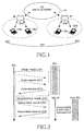
- FIG. 1 is a view illustrating the architecture of a conventional wireless local area network (WLAN) for supporting the infrastructure mode.
- WLAN wireless local area network
- a plurality of access points (APs) 120a and 120b are connected through one distribution system (DS) 110.
- the DS 110 is implemented with a wired network.
- a communication path is formed between the plurality of APs 120a and 120b.
- the plurality of APs 120a and 120b form constant service areas, and serve as bridges between STAs 130a, 130b, 130c and 130d and the DS 110.
- One AP and the STAs associated with the AP form a basic service set (BSS).
- BSS basic service set
- a unique BSS is formed on an AP-by-AP basis, and service is provided on a BSS-by-BSS basis.
- a plurality of BSSs formed by the APs 120a and 120b can be extended to extended service sets (ESSs).
- the STAs 130a, 130b, 130c and 130d must undergo an authentication procedure to access the WLAN through the APs 120a and 120b to which the STAs 130a, 130b, 130c and 130d belong. In other words, the STAs 130a, 130b, 130c and 130d are permitted to access the network through the authentication procedure.
- the state information contains encryption information (based on an encryption code) used to transfer data to the DS 110.
- a wireless station In the WLAN based on the architecture shown in FIG. 1 , a wireless station (STA) has mobility and hence can move from one BSS to another BSS. In this case, a handoff is required so that service being received from the one BSS can be continuously provided to the STA by another BSS.
- An AP to which the STA had physical layer connectivity prior to the handoff is referred to as a "prior-AP”
- a new AP to which the STA acquires physical layer connectivity after the handoff is referred to as a "new-AP”.
- the conventional handoff procedure refers to the mechanism or sequence of messages exchanged between the APs and the STA.
- physical layer connectivity and state information must be transferred from one AP to another AP with respect to the STA in consideration.
- the handoff is a physical layer function carried out by at least three participating entities, i.e., an STA, a prior-AP and a new-AP.
- the state information that is transferred typically consists of the client credentials (which allow the STA to gain network access) and some accounting information.
- An operation for transferring the state information can be performed by an inter access point protocol (IAPP).
- IAPP inter access point protocol
- Logical steps based on the handoff procedure are classified into a discovery phase and a reauthentication phase.
- the signal strength and the signal-to-noise ratio of a signal from the STA's current AP might degrade and cause it to initiate a handoff.
- the STA might not be able to communicate with its current AP (or prior-AP).
- the STA needs to find potential APs in range to associate to. This is accomplished by a MAC layer function (or scan function).
- scan function the STA listens for beacon messages sent out periodically by APs at a rate of 10 ms, on assigned channels.
- the STA can create a priority list, i.e., a list of APs prioritized by the received signal strength.
- Two kinds of scanning methods defined in the standard are based on an active mode and a passive mode.
- the STA sends additional probe broadcast packets on each channel and receives responses from APs.
- the STA actively searches or probes for potential APs.
- the STA sends a reauthentication request to potential APs according to the priority list in the above-described discovery phase.
- the reauthentication phase typically involves an authentication and a reassociation to the new AP.
- the reauthentication phase involves the transfer of credentials and other state information from the prior-AP. As mentioned earlier, this can be achieved through a protocol such as the IAPP.
- the reauthentication phase includes an authentication phase and a reassociation phase.
- FIG. 2 is a view illustrating a handoff procedure in the conventional WLAN. It is assumed in FIG. 2 that the discovery phase is performed in the active mode. The handoff procedure shown in FIG. 2 is divided into a probe phase 210 and a reauthentication phase 220.
- a wireless station (STA) sensing the need for the handoff transmits a probe request message to a plurality of unspecified APs at step 212.
- the probe request message is defined as information for asking each AP whether or not the handoff can be successfully performed.
- the APs Upon receiving the probe request message, the APs transmit probe response messages to the STA at step 214.
- the fact that certain APs have received the probe request message means that the APs are adjacent to the STA.
- the APs capable of receiving the probe request message are determined to be potential APs.
- the STA repeatedly performs the above-described operation on a channel-by-channel basis.
- the STA performs the reassociation phase 220 according to priorities of the potential APs registered in a priority list created in the discovery phase.
- the STA transmits a reassociation request message to a new AP at step 222.
- the new AP performs an inter access point protocol (IAPP) procedure with other APs at step 230.
- IAPP inter access point protocol
- the new AP receives credentials and other state information assigned to the STA.
- the new AP transmits, to the STA, a reassociation response message to the reassociation request message at step 224.
- IAPP inter access point protocol
- the conventional handoff procedure starts when the STA transmits a probe request message and ends when the STA receives a reassociation response message.
- three types of delay are incurred as in the following.
- the three types of delay include a probe delay incurred in the discovery phase, an authentication delay incurred in the authentication phase and a reassociation delay incurred in the reassociation phase.
- the present invention has been made in view of the above problems, and it is one object of the present invention to provide a method for minimizing handoff latencies.
- EP 1 124 400 discloses a method, wherein if a base station learns about its neighbours during handover process and afterwards establishes a relationship.
- GOPAL R ET AL "Policy based access router selections and context transfers in mobile IP network”; Conference on network control and engineering for quality of service, security and mobility; pages 3 - 14, 23-10-2002, XP002966424; discloses context transfer after or before handover, whereby in both cases the handover to the new access point is already initiated.
- STA wireless station
- APs access points
- AP prior-access point
- STA wireless station
- STA wireless station
- APs potential access points
- STA wireless station
- APs access points
- the present invention adopts a proactive caching technique to reduce a reassociation delay.
- a procedure of propagating state information of a corresponding wireless station (STA), i.e., context, from a prior-access point (AP) to potential APs must be performed irrespective of a handoff process.
- the potential APs are a set of APs with which the STA can associate.
- the potential APs In order for the context of the STA to be sent to the potential APs as described above, the potential APs must be managed on each AP. For this, the APs must generate and manage a neighborhood graph.
- the neighborhood graph defines connection relationships between the potential APs in the handoff process. A method for generating the neighborhood graph and a handoff procedure based on the proactive caching technique using the neighborhood graph will be described in detail herein below.
- a neighborhood graph is formed by the arrangement of APs configuring a wireless local area network (WLAN).
- WLAN wireless local area network
- the generation of the neighborhood graph is preferably achieved on an AP-by-AP basis.
- the first generation method allows a manager to manually generate the neighborhood graph.
- the first generation method allows the manager to configure and register neighborhood graphs on the AP-by-AP basis according to the arrangement of the APs and also allows the manager to update a neighborhood graph when the arrangement of APs is changed therein.
- the second generation method allows the manager to register the first neighborhood graph and also allows the neighborhood graph to be automatically changed when the arrangement of the APs is changed therein.
- the third generation method allows neighborhood graphs to be automatically generated on an AP-by-AP basis.
- the third generation method has a problem in that a handoff must be performed on the basis of an existing handoff procedure and a neighborhood graph is generated In other words, a procedure of confirming connection relationships on an AP-by-AP basis is required in the third generation method.
- the AP_B performs an inter-access point protocol (IAPP) procedure to receive context corresponding to the STA from the AP_A.
- IAPP inter-access point protocol
- AP_A and AP_B confirm the existence of the interconnection relationship therebetween for the handoff, such that a corresponding neighborhood graph can be updated.
- the handoff can be performed with respect to the STA that desires to move from AP_A to AP_B or from AP_B to AP_A without the IAPP procedure.
- a physical path connected between APs and a distance between the APs must be considered so that any one of the three types of generation methods can generate a neighborhood graph.
- the APs configuring the WLAN must be able to be physically connected to each other without going through any other AP so that connection relationships can be formed on the basis of the neighborhood graph.
- two APs physically connected to each other must be within a threshold distance range. Where the two APs are far away from each other, it is preferable that a handoff is performed according to an initial procedure for allowing a new AP to support communication.
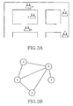
- FIG. 3A is a view illustrating the exemplary arrangement of APs configuring the WLAN to which the embodiment of the present invention is applied; and FIG. 3B is a view illustrating an exemplary neighborhood graph capable of being generated by the arrangement of APs shown in FIG. 3A .
- an AP_C is installed in a closed space with one gateway.
- a path in which the STA located at AP_C can move is defined by an AP_B.
- the STA located at AP_B can move not only to AP_A, AP_D and AP_E but also to AP_C, which are installed at passages (as physical connections).
- the STA located at AP_B allows a handoff process to be performed between AP_B and all other APs shown in FIG. 3A .
- APs to which the STA located at AP_A can directly associate without going through any other AP are defined by AP_B and AP_E.
- the STA located at AP_A allows a handoff process to be performed between AP_A and AP_B or AP_E.
- the STA located at AP_E can directly associate to all APs other than AP_C among APs shown in FIG. 3A . This means that the STA located at AP_E allows a handoff process to be performed between AP_E and any AP except for AP_C.
- APs to which the STA located at AP_D can directly associate without going through any other AP are defined by AP_B and AP_E.
- the STA located at AP_D allows a handoff process to be performed between AP_D and AP_B or AP_E.
- the reason why a handoff between AP_D and AP_A is not permitted is because a distance between AP_D and AP_A is a STA will reassociate with AP_B before AP_D.
- FIG. 3B shows a neighborhood graph generated by the connection relationships between the above-described APs.
- the neighborhood graph shown in FIG. 3B shows the connection relationships between all APs configuring the WLAN.
- each AP only needs to recognize potential APs capable of being associated therewith. For example, AP_A only needs to recognize AP_B and AP_E as its potential APs, while AP_B only needs to recognize AP_A, AP_C, AP_D and AP_E as its potential APs.
- a neighborhood graph on each AP can be generated by the manager or can be automatically generated according to an existing handoff procedure.
- an arbitrary AP Upon receiving a reassociation request message from a wireless station (STA), an arbitrary AP determines whether temporarily stored context corresponding to the STA is present. At this point, the arbitrary AP becomes a new-AP for the STA.
- the fact that the text is present means that a neighborhood graph with a prior-AP from which the STA moves is formed.
- the context is not present, it can be determined that the neighborhood graph with the prior-AP from which the STA moves is not formed.
- the new-AP receives the context corresponding to the STA from the prior-AP through the existing IAPP, updates a neighborhood graph and forms a connection with the prior-AP.
- the handoff can be performed with respect to the STA that moves from the prior-AP after the connection is formed.
- each AP recognizes its potential APs. Context of the STA belonging to the AP is sent to the potential APs. Even though the STA belonging to an arbitrary AP moves to any AP connected to the arbitrary AP, the time required for a reassociation phase in the handoff procedure can be minimized. That is, the proactive caching technique is based on some locality principle of mobility. In this environment, a reassociation pattern of the STA will be the sequence of APs that the STA gets associated with in a given interval of time.
- FIG. 4 is a conceptual view illustrating a handoff procedure based on the proactive caching technique in accordance with the embodiment of the present invention.
- STA wireless station
- the STA sends an association/reassociation request to AP_A at step 1.
- AP_A performs different operations according to whether the association or reassociation request is received from the STA.
- AP_A When the association request is received, AP_A performs an authentication process for the STA on the basis of a typical initial authentication procedure. If the authentication process is completed, AP_A sends, to the STA, a response message to the association request.
- AP_A When the reassociation request is received, AP_A performs different operations according to whether or not context corresponding to the STA has been temporarily stored. If the context corresponding to the STA has been temporarily stored, AP_A sends a response message to the STA in response to the reassociation request. On the other hand, if the context corresponding to the STA has been not temporarily stored, AP_A receives the context from an AP at which the STA was previously located through the typical IAPP procedure. Then, the response message to the reassociation request is sent to the STA. The STA performs communication with AP_A by receiving the response message from AP_A.
- AP_A transfers the context, such as security context, corresponding to the STA to AP_B indicating a potential AP in a handoff at step 2. Only one AP is shown as the potential AP in FIG. 4 . However, where a plurality of APs are present as potential APs, the context is propagated to the plurality of APs.
- AP_B stores the context transferred from AP_A in a cache. After moving to AP_B through a predetermined path, the STA sends a reassociation request to AP_B at step 3. In response to the reassociation request, AP_B performs communication with the STA according to the context previously transferred from AP_A. In other words, the reassociation between AP_B and the STA is performed according to the context.
- the present invention reduces a time delay incurred during the IAPP procedure and hence improves a communication rate.
- the embodiment of the present invention employs proactive caching technique in which context of a corresponding STA can be provided to at least one predicted AP to which the STA moves.
- a proactive caching technique in order for the proactive caching technique to be applied, an operation for transferring context of a corresponding STA from a prior-AP to a new-AP must be performed.
- each AP must be able to predict information about potential new-APs so that the proactive caching technique can be applied. This has been described above in relation to the neighborhood graph.
- FIG. 5 is a view illustrating a handoff procedure using the proactive caching technique in the WLAN in accordance with the embodiment of the present invention.
- context of a corresponding STA is transferred from a prior-AP to a new-AP before a reassociation process for the handoff is performed.
- AP_A is the prior-AP
- AP_B is the new-AP.
- the context of the corresponding STA is already temporarily stored.
- the STA sends a reassociation request message to AP_A at step 501.
- AP_A may already have stored the context of the STA using the proactive caching technique. Otherwise, if AP_A has not stored the context of the STA, AP_A can receive the context of the STA from the WLAN through the typical authentication procedure or receives the context of the STA from an AP at which the STA was previously located through the IAPP procedure.
- AP_A transmits a reassociation response message to the STA on the basis of the temporarily stored context corresponding to the STA at step 503. Then, AP_A propagates the temporarily stored context to a potential AP, i.e., AP_B at step 505.
- AP_A propagates the context of the STA to the plurality of potential APs.
- AP_B temporarily stores the context corresponding to the STA propagated from AP_A.
- the STA sends a reassociation request message to AP_B at step 507.
- AP_B determines whether the temporarily stored context corresponding to the STA is present. If the temporarily stored context corresponding to the STA is present in AP_B, AP_B transmits a reassociation response message to the STA on the basis of the context at step 509. As authentication is completed between the STA and AP_B, communication between the STA and AP_B is enabled.
- a state in which each AP cannot store context propagated from neighboring APs can be incurred due to insufficient cache capacity.
- the AP sequentially deletes the oldest contexts so that newly propagated context can be stored.
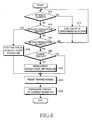
- FIG. 6 An operation of the AP when a handoff procedure is performed in accordance with the embodiment of the present invention will now be described in detail with respect to FIG. 6 .
- a procedure of receiving and storing context received from neighboring APs, a procedure of performing an operation in response to an association request, and a procedure of performing an operation in response to a reassociation request will now be described with reference to FIG. 6 .
- the AP determines whether context corresponding to a specific wireless station (STA) is received from handoff-capable neighboring APs that are managed by a neighborhood graph at step 610. Upon receiving the context corresponding to the specific STA, the AP proceeds to step 612, and stores the received context in its own cache.
- STA wireless station
- the AP determines, at step 614, whether an association request has been received from the STA, and determines, at step 616, whether a reassociation request has been received from the STA. If the association request has been received from an arbitrary STA, the AP proceeds to step 618 and performs a typical authentication procedure with an authentication server provided in a wireless network. Then, the AP configures context corresponding to the STA and stores the configured context in its own cache. On the other hand, if the reassociation request has been received, the AP determines that the STA has moved from another AP. Then, the AP proceeds to step 620 and determines whether context corresponding to the STA stored in the internal cache is present.
- the AP proceeds to step 622.
- the AP performs a typical IAPP procedure, and obtains the context corresponding to the STA from another AP at which the STA was previously located. If the AP recognizes another AP at which the STA was previously located, the IAPP procedure is performed only for the already recognized AP.
- the AP sends a response message to the STA.
- the response message corresponds to the association/reassociation request.
- the AP proceeds to step 626 after sending the response message, the AP refers to a neighborhood graph managed thereby and propagates the context of a corresponding STA to neighboring APs. This is to implement a fast handoff when a corresponding STA moves to any neighboring AP.
- the present invention can provide a method for simplifying a handoff procedure in a wireless local area network (WLAN), reducing a reassociation delay, and enabling a wireless station (STA) to quickly communicate with an access point (AP) to which the STA moves. Furthermore, the method in accordance with the present invention can provide not only secure quality of service but also high-speed roaming service.
- WLAN wireless local area network
- AP access point
- the present invention is applicable to all wireless communication systems and technologies, and as such may be utilized with CDMA, TDMA, FDMA, IMT, GSM, etc. systems and equipment, as well as IEEE 802.11 technology and equipment.
- APs as described above are analogous to base stations in telecommunication systems, while STAs are analogous to mobile terminals or stations.
- the invention relates to a method for enabling access points (APs) to support a handoff for at least one wireless station (STA) in a wireless network, the wireless network including the APs for covering constant service areas and the STA associated with one of the APs for receiving communication service, comprising the steps of:
- the invention relates to a method, wherein the context is information necessary for a reassociation to the arbitrary STA.
- the invention relates to a method, wherein the APs comprise base stations of a telecommunication system and the STAs comprise mobile terminals.
- the invention relates to a method for enabling access points (APs) to support a handoff for at least one wireless station (STA) in a wireless network, the wireless network including the APs for covering constant service areas and the STA associated to one of the APs for receiving communication service, comprising the steps of:
- the invention relates to a method, wherein the neighboring APs are handoff-capable APs, and are managed by a neighborhood graph on an AP-by-AP basis.
- the invention relates to a method, wherein the neighboring APs are APs to which the STA can directly associate without going through other APs, and wherein the neighboring APs are located within a predetermined threshold distance.
- the invention relates to a method, further comprising the step of:
- the invention relates to a method, wherein the context is information necessary for a reassociation to the arbitrary STA.
- the invention relates to a method, wherein the APs comprise base stations of a telecommunication system and the STAs comprise mobile terminals.
- the invention relates to a method for performing a handoff between access points (APs) and a wireless station (STA) in a wireless network, the wireless network including the APs for covering constant service areas and the STA associated to one of the APs for receiving communication service, comprising the steps of:
- the invention relates to a method, wherein the neighboring APs are handoff-capable APs, and are managed by a neighborhood graph on an AP-by-AP basis.
- the invention relates to a method, wherein the neighboring APs are APs to which the STA can directly associate without going through other APs, and wherein the neighboring APs are located within a predetermined threshold distance.
- the invention relates to a method, further comprising the step of:
- the invention relates to a method, wherein the context is information necessary for a reassociation to the STA.
- the invention relates to a method, wherein the APs comprise base stations of a telecommunication system and the STAs comprise mobile terminals.
- the invention relates to a method for enabling base stations to support a handoff for at least one wireless station (STA) in a wireless network, the wireless network including the base stations for covering constant service areas and the STA associated with one of the base stations for receiving communication service, comprising the steps of:
Abstract
Description
- The present invention relates to a method for performing a handoff in a fast and secure wireless network, and more particularly to a method for minimizing handoff latencies.
- Conventionally, a local area network (LAN) is a collection of personal terminals, main frames and workstations coupled to a communication link within a distance of 300 meters or less. The LAN is a high-speed communication network for allowing employees in a company to be aware of information, i.e., a distance in which an electric current or radio wave signal can be correctly transferred between the personal terminals, to commonly and most effectively use equipment installed in the company's building. As LANs, wired networks for directly transferring an electrical signal through the communication link have been initially used. The trend has been to replace the wired networks with wireless networks for transferring a signal using a radio wave in accordance with the development of wireless protocols. LANs based on these wireless networks are referred to as wireless local area networks (WLANs). WLANs are based on Institute of Electrical and Electronics Engineers (IEEE) 802.11. IEEE 802.11-based WLANs have seen immense growth in the last few years. It is predicted that the IEEE 802.11-based WLANs will be rapidly developed in the future because of an advantageous effect of convenient network connectivity.
- IEEE 802.11 allows for two operating modes, i.e., an ad hoc mode and an infrastructure mode, in relation to a media access control (MAC) layer. In the ad hoc mode, two or more wireless stations (STAs) recognize each other and establish a peer-to-peer communication without any existing infrastructure. Meanwhile, in the infrastructure mode, there is a fixed entity called an access point (AP) that bridges all data between the STAs associated with the AP. The AP and the STAs associated with the AP form a basic service set (BSS) communicating on the unlicensed radio frequency (RF) spectrum.
-
FIG. 1 is a view illustrating the architecture of a conventional wireless local area network (WLAN) for supporting the infrastructure mode. - Referring to
FIG. 1 , a plurality of access points (APs) 120a and 120b are connected through one distribution system (DS) 110. The DS 110 is implemented with a wired network. A communication path is formed between the plurality ofAPs APs STAs APs APs STAs STAs - In the WLAN based on the architecture shown in
FIG. 1 , a wireless station (STA) has mobility and hence can move from one BSS to another BSS. In this case, a handoff is required so that service being received from the one BSS can be continuously provided to the STA by another BSS. An AP to which the STA had physical layer connectivity prior to the handoff is referred to as a "prior-AP", while a new AP to which the STA acquires physical layer connectivity after the handoff is referred to as a "new-AP". - The conventional handoff procedure refers to the mechanism or sequence of messages exchanged between the APs and the STA. In the conventional handoff procedure, physical layer connectivity and state information must be transferred from one AP to another AP with respect to the STA in consideration. The handoff is a physical layer function carried out by at least three participating entities, i.e., an STA, a prior-AP and a new-AP. The state information that is transferred typically consists of the client credentials (which allow the STA to gain network access) and some accounting information. An operation for transferring the state information can be performed by an inter access point protocol (IAPP). For an IEEE 802.11 network that has no access control mechanism, there would be a nominal difference between a completion association and a handoff/reassociation. Looking at it another way, handoff latency would be strictly greater than association latency as there is an additional inter-access point communication delay involved.
- Logical steps based on the handoff procedure are classified into a discovery phase and a reauthentication phase.
- Attributing to mobility, the signal strength and the signal-to-noise ratio of a signal from the STA's current AP (or prior-AP) might degrade and cause it to initiate a handoff. At this point, the STA might not be able to communicate with its current AP (or prior-AP). Thus, the STA needs to find potential APs in range to associate to. This is accomplished by a MAC layer function (or scan function). During a scan, the STA listens for beacon messages sent out periodically by APs at a rate of 10 ms, on assigned channels. Thus, the STA can create a priority list, i.e., a list of APs prioritized by the received signal strength. Two kinds of scanning methods defined in the standard are based on an active mode and a passive mode. As the names suggest, in the active mode, apart from listening to beacon messages (which is passive), the STA sends additional probe broadcast packets on each channel and receives responses from APs. Thus, the STA actively searches or probes for potential APs.
- The STA sends a reauthentication request to potential APs according to the priority list in the above-described discovery phase. The reauthentication phase typically involves an authentication and a reassociation to the new AP. The reauthentication phase involves the transfer of credentials and other state information from the prior-AP. As mentioned earlier, this can be achieved through a protocol such as the IAPP. The reauthentication phase includes an authentication phase and a reassociation phase.
-
FIG. 2 is a view illustrating a handoff procedure in the conventional WLAN. It is assumed inFIG. 2 that the discovery phase is performed in the active mode. The handoff procedure shown inFIG. 2 is divided into aprobe phase 210 and areauthentication phase 220. - Referring to
FIG. 2 , a wireless station (STA) sensing the need for the handoff transmits a probe request message to a plurality of unspecified APs atstep 212. The probe request message is defined as information for asking each AP whether or not the handoff can be successfully performed. Upon receiving the probe request message, the APs transmit probe response messages to the STA atstep 214. Here, the fact that certain APs have received the probe request message means that the APs are adjacent to the STA. Thus, the APs capable of receiving the probe request message are determined to be potential APs. The STA repeatedly performs the above-described operation on a channel-by-channel basis. - On the other hand, the STA performs the
reassociation phase 220 according to priorities of the potential APs registered in a priority list created in the discovery phase. The STA transmits a reassociation request message to a new AP atstep 222. In response to the reassociation request message, the new AP performs an inter access point protocol (IAPP) procedure with other APs atstep 230. Through the IAPP procedure, the new AP receives credentials and other state information assigned to the STA. Then, the new AP transmits, to the STA, a reassociation response message to the reassociation request message atstep 224. - As described above, the conventional handoff procedure starts when the STA transmits a probe request message and ends when the STA receives a reassociation response message. During the handoff procedure, three types of delay are incurred as in the following. The three types of delay include a probe delay incurred in the discovery phase, an authentication delay incurred in the authentication phase and a reassociation delay incurred in the reassociation phase.
- 1. Probe Delay: Messages transmitted for an active scan at the
probe phase 210 shown inFIG. 2 are probe messages. The latency for this process is referred to as a probe delay. The STA transmits a probe request message and waits for responses from APs on each channel. The time during which the STA waits on a particular channel after sending the probe request message corresponds to probe-wait latency. This is determined to be a time difference between subsequent probe request messages. Here, the time is subsequent between PROBE REQUEST MESSAGES on differing channels. According to the above procedure, it has been found that the traffic on the channel and the timing of probe response messages affect the probe-wait time. - 2. Authentication Delay: This is the latency (not shown in
FIG. 2 ) incurred during which authentication frames are exchanged. Authentication consists of two or four consecutive frames depending on the authentication method used by the AP. Some wireless network interface cards (NICs) try to initiate a reassociation prior to the authentication, which causes an additional delay in the handoff process. - 3. Reassociation Delay: This is the latency incurred during which reassociation frames are exchanged in the
reassociation phase 220 shown inFIG. 2 . If an authentication process is successful, the STA sends a reassociation request frame to the AP, receives a reassociation response frame, and completes the handoff. Where the IAPP procedure between a new AP and other APs is additionally required, the reassociation delay will further increase. - According to the above, messages during the probe delay form the discovery phase, while the authentication and reassociation delays form the reauthentication phase. Apart from the latencies discussed above, there will potentially be a bridging delay caused by the time taken for the MAC address updates to Ethernet switches which form the distribution system (i.e., the backbone Ethernet). It can be seen that many latencies are incurred while a handoff between an STA and APs is performed in the conventional WLAN. There are problems in that the latencies not only affect the quality of service (QoS) but also disable high-speed roaming.
- Therefore, the present invention has been made in view of the above problems, and it is one object of the present invention to provide a method for minimizing handoff latencies.
-
EP 1 124 400 discloses a method, wherein if a base station learns about its neighbours during handover process and afterwards establishes a relationship. GOPAL R ET AL: "Policy based access router selections and context transfers in mobile IP network"; Conference on network control and engineering for quality of service, security and mobility; pages 3 - 14, 23-10-2002, XP002966424; discloses context transfer after or before handover, whereby in both cases the handover to the new access point is already initiated. - It is another object of the present invention to provide a method for transferring state information of a corresponding wireless station (STA) to access points (APs) before a handoff is performed.
- It is another object of the present invention to provide a handoff method capable of eliminating a tunneling procedure between a prior-access point (AP) and a new-AP and a procedure of transferring state information of a corresponding wireless station (STA) through the tunneling procedure.
- It is another object of the present invention to provide a method for generating a neighborhood graph needed to send state information of a wireless station (STA) to potential access points (APs).
- It is yet another object of the present invention to provide a method for propagating state information of a wireless station (STA) to neighboring access points (APs) on the basis of a neighborhood graph.
- The above and other objects, features and other advantages of the present invention will be more clearly understood from the following detailed description taken in conjunction with the accompanying drawings, in which:
-
FIG. 1 is a view illustrating the architecture of a conventional wireless local area network (WLAN); -
FIG. 2 is a view illustrating a handoff procedure in the conventional WLAN; -
FIGS. 3A and 3B are views illustrating an operation for generating a neighborhood graph in accordance with an embodiment of the present invention; -
FIG. 4 is a conceptual view illustrating the handoff procedure in accordance with the embodiment of the present invention; -
FIG. 5 is a view illustrating the handoff procedure in a wireless local area network (WLAN) in accordance with the embodiment of the present invention; and -
FIG. 6 is a flow chart illustrating operations of access points (APs) in accordance with the embodiment of the present invention. - A preferred embodiment of the present invention will now be described in detail with reference to the annexed drawings. In the following description, the present invention proposes the preferred embodiment to achieve the above and other objects. However, other embodiments of the present invention can be drawn from the following description of the present invention.
- The present invention adopts a proactive caching technique to reduce a reassociation delay. In order for the proactive caching technique to be adopted, a procedure of propagating state information of a corresponding wireless station (STA), i.e., context, from a prior-access point (AP) to potential APs must be performed irrespective of a handoff process. The potential APs are a set of APs with which the STA can associate. In order for the context of the STA to be sent to the potential APs as described above, the potential APs must be managed on each AP. For this, the APs must generate and manage a neighborhood graph. The neighborhood graph defines connection relationships between the potential APs in the handoff process. A method for generating the neighborhood graph and a handoff procedure based on the proactive caching technique using the neighborhood graph will be described in detail herein below.
- In accordance with the present invention, a neighborhood graph is formed by the arrangement of APs configuring a wireless local area network (WLAN). As potential APs corresponding to each of the APs configuring the WLAN are different, the generation of the neighborhood graph is preferably achieved on an AP-by-AP basis. There are three types of neighborhood graph generation methods. The first generation method allows a manager to manually generate the neighborhood graph. The first generation method allows the manager to configure and register neighborhood graphs on the AP-by-AP basis according to the arrangement of the APs and also allows the manager to update a neighborhood graph when the arrangement of APs is changed therein. The second generation method allows the manager to register the first neighborhood graph and also allows the neighborhood graph to be automatically changed when the arrangement of the APs is changed therein. The third generation method allows neighborhood graphs to be automatically generated on an AP-by-AP basis. However, the third generation method has a problem in that a handoff must be performed on the basis of an existing handoff procedure and a neighborhood graph is generated In other words, a procedure of confirming connection relationships on an AP-by-AP basis is required in the third generation method. For example, where the STA located at an AP_A tries to first perform a handoff process to an AP_B by which no handoff for the STA was previously performed, the AP_B performs an inter-access point protocol (IAPP) procedure to receive context corresponding to the STA from the AP_A. Then, AP_A and AP_B confirm the existence of the interconnection relationship therebetween for the handoff, such that a corresponding neighborhood graph can be updated. After the neighborhood graph is updated, the handoff can be performed with respect to the STA that desires to move from AP_A to AP_B or from AP_B to AP_A without the IAPP procedure.
- On the other hand, a physical path connected between APs and a distance between the APs must be considered so that any one of the three types of generation methods can generate a neighborhood graph. In other words, the APs configuring the WLAN must be able to be physically connected to each other without going through any other AP so that connection relationships can be formed on the basis of the neighborhood graph. Furthermore, two APs physically connected to each other must be within a threshold distance range. Where the two APs are far away from each other, it is preferable that a handoff is performed according to an initial procedure for allowing a new AP to support communication.
- An example of generating a neighborhood graph to be applied in accordance with the embodiment of the present invention will now be described in detail.
-
FIG. 3A is a view illustrating the exemplary arrangement of APs configuring the WLAN to which the embodiment of the present invention is applied; andFIG. 3B is a view illustrating an exemplary neighborhood graph capable of being generated by the arrangement of APs shown inFIG. 3A . - As shown in
FIG. 3A , an AP_C is installed in a closed space with one gateway. Thus, a path in which the STA located at AP_C can move is defined by an AP_B. This means that only a handoff process between AP_C and AP_B can be performed with respect to the STA located at AP_C. The STA located at AP_B can move not only to AP_A, AP_D and AP_E but also to AP_C, which are installed at passages (as physical connections). In other words, the STA located at AP_B allows a handoff process to be performed between AP_B and all other APs shown inFIG. 3A . APs to which the STA located at AP_A can directly associate without going through any other AP are defined by AP_B and AP_E. Thus, the STA located at AP_A allows a handoff process to be performed between AP_A and AP_B or AP_E. The STA located at AP_E can directly associate to all APs other than AP_C among APs shown inFIG. 3A . This means that the STA located at AP_E allows a handoff process to be performed between AP_E and any AP except for AP_C. APs to which the STA located at AP_D can directly associate without going through any other AP are defined by AP_B and AP_E. Thus, the STA located at AP_D allows a handoff process to be performed between AP_D and AP_B or AP_E. The reason why a handoff between AP_D and AP_A is not permitted is because a distance between AP_D and AP_A is a STA will reassociate with AP_B before AP_D. -
FIG. 3B shows a neighborhood graph generated by the connection relationships between the above-described APs. The neighborhood graph shown inFIG. 3B shows the connection relationships between all APs configuring the WLAN. In accordance with the present invention, each AP only needs to recognize potential APs capable of being associated therewith. For example, AP_A only needs to recognize AP_B and AP_E as its potential APs, while AP_B only needs to recognize AP_A, AP_C, AP_D and AP_E as its potential APs. As described above, a neighborhood graph on each AP can be generated by the manager or can be automatically generated according to an existing handoff procedure. - An operation for allowing each AP to automatically generate the neighborhood graph will now be described. Upon receiving a reassociation request message from a wireless station (STA), an arbitrary AP determines whether temporarily stored context corresponding to the STA is present. At this point, the arbitrary AP becomes a new-AP for the STA. The fact that the text is present means that a neighborhood graph with a prior-AP from which the STA moves is formed. On the other hand, if the context is not present, it can be determined that the neighborhood graph with the prior-AP from which the STA moves is not formed. In this case, the new-AP receives the context corresponding to the STA from the prior-AP through the existing IAPP, updates a neighborhood graph and forms a connection with the prior-AP. In accordance with the handoff procedure of the present invention, the handoff can be performed with respect to the STA that moves from the prior-AP after the connection is formed.
- In accordance with the proactive caching technique of the present invention, each AP recognizes its potential APs. Context of the STA belonging to the AP is sent to the potential APs. Even though the STA belonging to an arbitrary AP moves to any AP connected to the arbitrary AP, the time required for a reassociation phase in the handoff procedure can be minimized. That is, the proactive caching technique is based on some locality principle of mobility. In this environment, a reassociation pattern of the STA will be the sequence of APs that the STA gets associated with in a given interval of time.
- Proactive caching technique for reducing a reassociation delay in accordance with the embodiment of the present invention will now be described in detail with reference to
FIG. 4.FIG. 4 is a conceptual view illustrating a handoff procedure based on the proactive caching technique in accordance with the embodiment of the present invention. Here, it is assumed that a wireless station (STA) moves from an AP_A to an AP_B. - Referring to
FIG. 4 , the STA sends an association/reassociation request to AP_A at step 1. AP_A performs different operations according to whether the association or reassociation request is received from the STA. - When the association request is received, AP_A performs an authentication process for the STA on the basis of a typical initial authentication procedure. If the authentication process is completed, AP_A sends, to the STA, a response message to the association request.
- When the reassociation request is received, AP_A performs different operations according to whether or not context corresponding to the STA has been temporarily stored. If the context corresponding to the STA has been temporarily stored, AP_A sends a response message to the STA in response to the reassociation request. On the other hand, if the context corresponding to the STA has been not temporarily stored, AP_A receives the context from an AP at which the STA was previously located through the typical IAPP procedure. Then, the response message to the reassociation request is sent to the STA. The STA performs communication with AP_A by receiving the response message from AP_A.
- On the other hand, AP_A transfers the context, such as security context, corresponding to the STA to AP_B indicating a potential AP in a handoff at
step 2. Only one AP is shown as the potential AP inFIG. 4 . However, where a plurality of APs are present as potential APs, the context is propagated to the plurality of APs. AP_B stores the context transferred from AP_A in a cache. After moving to AP_B through a predetermined path, the STA sends a reassociation request to AP_B atstep 3. In response to the reassociation request, AP_B performs communication with the STA according to the context previously transferred from AP_A. In other words, the reassociation between AP_B and the STA is performed according to the context. Thus, the present invention reduces a time delay incurred during the IAPP procedure and hence improves a communication rate. - The embodiment of the present invention employs proactive caching technique in which context of a corresponding STA can be provided to at least one predicted AP to which the STA moves. In other words, in order for the proactive caching technique to be applied, an operation for transferring context of a corresponding STA from a prior-AP to a new-AP must be performed. Furthermore, each AP must be able to predict information about potential new-APs so that the proactive caching technique can be applied. This has been described above in relation to the neighborhood graph.
- In accordance with the embodiment of the present invention, a method for a reassociation delay using the proactive caching technique will now be described in detail with reference to
FIG. 5. FIG. 5 is a view illustrating a handoff procedure using the proactive caching technique in the WLAN in accordance with the embodiment of the present invention. - Referring to
FIG. 5 , it can be seen that context of a corresponding STA is transferred from a prior-AP to a new-AP before a reassociation process for the handoff is performed. InFIG. 5 , it is assumed that AP_A is the prior-AP and AP_B is the new-AP. Furthermore, it is assumed that the context of the corresponding STA is already temporarily stored. - Referring to
FIG. 5 , the STA sends a reassociation request message to AP_A atstep 501. At this time, AP_A may already have stored the context of the STA using the proactive caching technique. Otherwise, if AP_A has not stored the context of the STA, AP_A can receive the context of the STA from the WLAN through the typical authentication procedure or receives the context of the STA from an AP at which the STA was previously located through the IAPP procedure. AP_A transmits a reassociation response message to the STA on the basis of the temporarily stored context corresponding to the STA atstep 503. Then, AP_A propagates the temporarily stored context to a potential AP, i.e., AP_B atstep 505. At this time, information of the potential AP can be obtained from the above-described neighborhood graph. It is assumed that the number of potential APs is one as shown inFIG. 5 , but a plurality of potential APs can be present. If the multiple potential APs are present, AP_A propagates the context of the STA to the plurality of potential APs. AP_B temporarily stores the context corresponding to the STA propagated from AP_A. - At the time of the need for a handoff to AP_B, the STA sends a reassociation request message to AP_B at
step 507. Upon receiving the reassociation request message, AP_B determines whether the temporarily stored context corresponding to the STA is present. If the temporarily stored context corresponding to the STA is present in AP_B, AP_B transmits a reassociation response message to the STA on the basis of the context atstep 509. As authentication is completed between the STA and AP_B, communication between the STA and AP_B is enabled. - Where the proactive caching technique is applied as described above, a state in which each AP cannot store context propagated from neighboring APs can be incurred due to insufficient cache capacity. In this case, the AP sequentially deletes the oldest contexts so that newly propagated context can be stored.
- An operation of the AP when a handoff procedure is performed in accordance with the embodiment of the present invention will now be described in detail with respect to
FIG. 6 . A procedure of receiving and storing context received from neighboring APs, a procedure of performing an operation in response to an association request, and a procedure of performing an operation in response to a reassociation request will now be described with reference toFIG. 6 . - Referring to
FIG. 6 , the AP determines whether context corresponding to a specific wireless station (STA) is received from handoff-capable neighboring APs that are managed by a neighborhood graph atstep 610. Upon receiving the context corresponding to the specific STA, the AP proceeds to step 612, and stores the received context in its own cache. - On the other hand, the AP determines, at
step 614, whether an association request has been received from the STA, and determines, atstep 616, whether a reassociation request has been received from the STA. If the association request has been received from an arbitrary STA, the AP proceeds to step 618 and performs a typical authentication procedure with an authentication server provided in a wireless network. Then, the AP configures context corresponding to the STA and stores the configured context in its own cache. On the other hand, if the reassociation request has been received, the AP determines that the STA has moved from another AP.
Then, the AP proceeds to step 620 and determines whether context corresponding to the STA stored in the internal cache is present. If the context corresponding to the STA is not present in the internal cache, the AP proceeds to step 622. At theabove step 622, the AP performs a typical IAPP procedure, and obtains the context corresponding to the STA from another AP at which the STA was previously located. If the AP recognizes another AP at which the STA was previously located, the IAPP procedure is performed only for the already recognized AP. - When the AP proceeds from the
above step - As apparent from the above description, the present invention can provide a method for simplifying a handoff procedure in a wireless local area network (WLAN), reducing a reassociation delay, and enabling a wireless station (STA) to quickly communicate with an access point (AP) to which the STA moves. Furthermore, the method in accordance with the present invention can provide not only secure quality of service but also high-speed roaming service.
- Furthermore, the present invention is applicable to all wireless communication systems and technologies, and as such may be utilized with CDMA, TDMA, FDMA, IMT, GSM, etc. systems and equipment, as well as IEEE 802.11 technology and equipment. APs as described above are analogous to base stations in telecommunication systems, while STAs are analogous to mobile terminals or stations.
- Although the preferred embodiments of the present invention have been disclosed for illustrative purposes, those skilled in the art will appreciate that various modifications, additions and substitutions are possible, without departing from the scope of the invention. Therefore, the present invention is not limited to the above-described embodiments and drawings.
- In an aspect, the invention relates to a method for enabling access points (APs) to support a handoff for at least one wireless station (STA) in a wireless network, the wireless network including the APs for covering constant service areas and the STA associated with one of the APs for receiving communication service, comprising the steps of:
- (a) generating a neighborhood graph configured by handoff-capable neighboring APs;
- (b) receiving context of an arbitrary STA propagated from the neighboring APs on the basis of the neighborhood graph; and
- (c) after performing a reassociation process for the arbitrary STA that has moved from a neighboring AP using the received context, referring to the neighborhood graph and propagating the context to the neighboring APs.
In a further aspect, the invention relates to a method, wherein the neighborhood graph is generated on an AP-by-AP basis.
In a further aspect, the invention relates to a method, wherein the neighboring APs are APs to which the STA can directly associate without going through other APs, and wherein the neighboring APs are located within a predetermined threshold distance.
In a further aspect, the invention relates to a method, further comprising the step of: - (d) when the context of the arbitrary STA is not present, forming a channel with an AP at which the arbitrary STA was located before movement, and receiving the context of the arbitrary STA from the AP coupled to the formed channel.
- In a further aspect, the invention relates to a method, wherein the context is information necessary for a reassociation to the arbitrary STA.
- In a further aspect, the invention relates to a method, wherein the APs comprise base stations of a telecommunication system and the STAs comprise mobile terminals.
- In an aspect, the invention relates to a method for enabling access points (APs) to support a handoff for at least one wireless station (STA) in a wireless network, the wireless network including the APs for covering constant service areas and the STA associated to one of the APs for receiving communication service, comprising the steps of:
- (a) obtaining context of an arbitrary STA according to an association or reassociation request, and performing an association to the arbitrary STA on the basis of the context; and
- (b) propagating the context to neighboring APs,
- In a further aspect, the invention relates to a method, wherein the neighboring APs are handoff-capable APs, and are managed by a neighborhood graph on an AP-by-AP basis.
- In a further aspect, the invention relates to a method, wherein the neighboring APs are APs to which the STA can directly associate without going through other APs, and wherein the neighboring APs are located within a predetermined threshold distance.
- In a further aspect, the invention relates to a method, further comprising the step of:
- (c) when the context of the arbitrary STA is not present, forming a channel with an AP at which the arbitrary STA was located before movement, and receiving the context of the arbitrary STA from the AP coupled to the formed channel.
- In a further aspect, the invention relates to a method, wherein the context is information necessary for a reassociation to the arbitrary STA.
- In a further aspect, the invention relates to a method, wherein the APs comprise base stations of a telecommunication system and the STAs comprise mobile terminals.
- In an aspect, the invention relates to a method for performing a handoff between access points (APs) and a wireless station (STA) in a wireless network, the wireless network including the APs for covering constant service areas and the STA associated to one of the APs for receiving communication service, comprising the steps of:
- (a) allowing the STA to send an association or reassociation request message;
- (b) when context of the STA is stored in an AP receiving the association or reassociation request message, sending an association or reassociation response message to the STA and propagating the context to handoff-capable neighboring APs; and
- (c) when the context of the STA is not stored in an AP receiving the association or reassociation request message, sending an association or reassociation response message after obtaining the context of the STA, and propagating the obtained context to handoff-capable neighboring APs,
- In a further aspect, the invention relates to a method, wherein the neighboring APs are handoff-capable APs, and are managed by a neighborhood graph on an AP-by-AP basis.
- In a further aspect, the invention relates to a method, wherein the neighboring APs are APs to which the STA can directly associate without going through other APs, and wherein the neighboring APs are located within a predetermined threshold distance.
- In a further aspect, the invention relates to a method, further comprising the step of:
- (d) when the context of the STA is not present, forming a channel with an AP at which the STA was located before movement, and receiving the context of the STA from the AP coupled to the formed channel.
- In a further aspect, the invention relates to a method, wherein the context is information necessary for a reassociation to the STA.
- In a further aspect, the invention relates to a method, wherein the APs comprise base stations of a telecommunication system and the STAs comprise mobile terminals.
- In an aspect, the invention relates to a method for enabling base stations to support a handoff for at least one wireless station (STA) in a wireless network, the wireless network including the base stations for covering constant service areas and the STA associated with one of the base stations for receiving communication service, comprising the steps of:
- (a) generating a neighborhood graph configured by handoff-capable neighboring base stations;
- (b) receiving context of an arbitrary STA propagated from the neighboring base stations on the basis of the neighborhood graph; and
- (c) after performing a reassociation process for the arbitrary STA that has moved from a neighboring base station using the received context, referring to the neighborhood graph and propagating the context to the neighboring base stations.
Claims (19)
- A method of generating a neighborhood graph accessible by an access point, the access point through which a station requested access to a wireless network, the method comprising:determining arrangement information of neighboring access points in the wireless network; andregistering information on one or more neighboring access points (APB) of the wireless network that are fit for handoff of the station (STA) thereto from the access point (APA), in the neighborhood graph accessible by the access point, andpropagating (505) context relating to the station (STA) to the neighboring access points (APB) of the access point (APA), as defined by the neighborhood graph, in response to the access point (APA) transmitting (503) a reassociation response message to the station.
- The method according to claim 1, wherein the information on one or more access points comprises connection relationship information between the access point and the one or more access points in the wireless network.
- The method according to claim 1, wherein the neighborhood graph is provided in one of the access point and a server of the wireless network accessible by the access point.
- The method according to claim 1, the method further comprising registering a prior access point of the station as fit for handoff of the station thereto from the access point, in the neighborhood graph, in response to a re-association of the station.
- The method according to claim 4, further comprising determining whether context of the station is present in the access point in response to a re-association signal of the station.
- The method according to claim 5, further comprising receiving the context from the prior access point in response to the context not being present in the determining step.
- The method according to claim 1, the method further comprising:outputting a response message including context of the station to another access point in response to a context request signal from the another access point; andregistering the another access point as fit for handoff of the station thereto from the access point, in the neighborhood graph accessible by the access point.
- The method according to claim 1, the method further comprising:outputting a context request signal requesting context of the station to a prior access point of the station;receiving a response message including the context of the station responsive to the context request signal from the prior access point of the station; andregistering the prior access point as fit for handoff of the station thereto from the access point, in the neighborhood graph accessible by the access point.
- The method according to one of claims 1 and 8, wherein each of the one or more access points or the another access point or the prior access point is an access point to which the station in handoff is directly associable from the access point without going through another access point of the wireless network.
- An access point through which a station accesses a wireless network, the access point comprising a neighborhood graph for containing information on one or more neighboring access points of the wireless network that are fit for handoff of the station thereto from the access point, the access point being arranged for propagating context relating to the station to the neighboring access points of the access point, as defined by the neighborhood graph, in response to the access point transmitting a reassociation response message to the station.
- The access point according to claim 10, wherein the information on one or more access points or the neighborhood graph comprises connection relationship information between the access point and the one or more access points in the wireless network.
- The access point according to claim 10, wherein each of the one or more access points is an access point to which the station in handoff is directly associable from the access point without going through another access point of the wireless network.
- The access point according to claim 10, wherein the neighborhood graph is generated on an access point-by-access point basis.
- The access point according to claim 10, wherein the wireless network includes at least one access point, and the neighborhood graph comprises a data structure containing information on one or more access points of the wireless network that are fit for handoff of the station thereto from a corresponding one of the at least one access point, for each of the at least one access point.
- The access point according to claim 10, the access point further compris ing:a storage for storing information including context of the station, wherein the access point determines whether the context is present in the storage in response to a re-association signal of the station, and registers a prior access point of the station as fit for handoff of the station thereto from the access point in response to the context not being present in the storage.
- The access point according to claim 15, wherein the registers is provided in one of the access point and a server of the wireless network accessible by the access point.
- The access point according to claim 1 5, wherein the storage is a cache for temporarily storing the information including the cont ext, and the access point deletes the oldest context to store newly received context in res ponse to insufficient storage capacity.
- The access point according to claim 10, the access point further comprising:receiving means for receiving a reassociation request message from a wirel ess station (STA);determining means for determining whether temporarily stored context corres ponding to the STA is present; and,receiving means for receiving the context corresponding to the STA from a prior-AP through an existing inter-access point protocol (IAPP), if the context is not present;wherein the access point is arranged to update the neighborhood graph co mprising connection relationships of access points in the wireless communication sy stem, after the context has been received.
- Computer-readable medium comprising program code adapted to carry out the method of claims 1-9 when running on a computer.
Applications Claiming Priority (3)
| Application Number | Priority Date | Filing Date | Title |
|---|---|---|---|
| US42510902P | 2002-11-08 | 2002-11-08 | |
| US425109P | 2002-11-08 | ||
| EP20030078527 EP1418711B1 (en) | 2002-11-08 | 2003-11-10 | Method for performing handoff in wireless network |
Related Parent Applications (2)
| Application Number | Title | Priority Date | Filing Date |
|---|---|---|---|
| EP20030078527 Division EP1418711B1 (en) | 2002-11-08 | 2003-11-10 | Method for performing handoff in wireless network |
| EP03078527.3 Division | 2003-11-10 |
Publications (4)
| Publication Number | Publication Date |
|---|---|
| EP1521402A2 EP1521402A2 (en) | 2005-04-06 |
| EP1521402A3 EP1521402A3 (en) | 2009-04-01 |
| EP1521402B1 true EP1521402B1 (en) | 2012-06-20 |
| EP1521402B8 EP1521402B8 (en) | 2012-10-17 |
Family
ID=32108174
Family Applications (4)
| Application Number | Title | Priority Date | Filing Date |
|---|---|---|---|
| EP20030078527 Expired - Lifetime EP1418711B1 (en) | 2002-11-08 | 2003-11-10 | Method for performing handoff in wireless network |
| EP20040078551 Expired - Fee Related EP1521403B1 (en) | 2002-11-08 | 2003-11-10 | Method for performing handoff in a wireless network |
| EP20040078550 Expired - Fee Related EP1521402B8 (en) | 2002-11-08 | 2003-11-10 | Method for performing handoff in a wireless network |
| EP20040078549 Ceased EP1526683A3 (en) | 2002-11-08 | 2003-11-10 | Method for handoff in a wireless network |
Family Applications Before (2)
| Application Number | Title | Priority Date | Filing Date |
|---|---|---|---|
| EP20030078527 Expired - Lifetime EP1418711B1 (en) | 2002-11-08 | 2003-11-10 | Method for performing handoff in wireless network |
| EP20040078551 Expired - Fee Related EP1521403B1 (en) | 2002-11-08 | 2003-11-10 | Method for performing handoff in a wireless network |
Family Applications After (1)
| Application Number | Title | Priority Date | Filing Date |
|---|---|---|---|
| EP20040078549 Ceased EP1526683A3 (en) | 2002-11-08 | 2003-11-10 | Method for handoff in a wireless network |
Country Status (8)
| Country | Link |
|---|---|
| US (4) | US8838103B2 (en) |
| EP (4) | EP1418711B1 (en) |
| JP (5) | JP3863140B2 (en) |
| KR (4) | KR100448318B1 (en) |
| CN (5) | CN100450273C (en) |
| AT (1) | ATE422758T1 (en) |
| DE (1) | DE60326114D1 (en) |
| ES (1) | ES2319630T3 (en) |
Cited By (1)
| Publication number | Priority date | Publication date | Assignee | Title |
|---|---|---|---|---|
| US11516701B2 (en) | 2012-03-06 | 2022-11-29 | Interdigital Patent Holdings, Inc. | Supporting a large number of devices in wireless communications |
Families Citing this family (112)
| Publication number | Priority date | Publication date | Assignee | Title |
|---|---|---|---|---|
| US6799054B2 (en) * | 2002-05-06 | 2004-09-28 | Extricom, Ltd. | Collaboration between wireless LAN access points using wired lan infrastructure |
| US20030206532A1 (en) * | 2002-05-06 | 2003-11-06 | Extricom Ltd. | Collaboration between wireless lan access points |
| US20050195786A1 (en) * | 2002-08-07 | 2005-09-08 | Extricom Ltd. | Spatial reuse of frequency channels in a WLAN |
| US7697549B2 (en) * | 2002-08-07 | 2010-04-13 | Extricom Ltd. | Wireless LAN control over a wired network |
| KR100501323B1 (en) * | 2002-12-16 | 2005-07-18 | 삼성전자주식회사 | Method and Apparatus for the realization of mobility by using WLAN Voice terminal at the ISDN switching system |
| US7263357B2 (en) * | 2003-01-14 | 2007-08-28 | Samsung Electronics Co., Ltd. | Method for fast roaming in a wireless network |
| US20050047381A1 (en) * | 2003-01-27 | 2005-03-03 | Proxim Corporation, A Delaware Corporation | System and method for a topology map related to access point usage in a wireless network |
| US20050014505A1 (en) * | 2003-01-27 | 2005-01-20 | Proxim Corporation, A Delaware Corporation | System and method for sending data to a mobile device in a wireless network |
| US7869822B2 (en) * | 2003-02-24 | 2011-01-11 | Autocell Laboratories, Inc. | Wireless network apparatus and system field of the invention |
| US7274930B2 (en) * | 2003-02-24 | 2007-09-25 | Autocell Laboratories, Inc. | Distance determination program for use by devices in a wireless network |
| US20040184422A1 (en) * | 2003-03-17 | 2004-09-23 | Interdigital Technology Corporation | Method and apparatus for performing a handoff in an inter-extended service set (I-ESS) |
| US7536714B2 (en) * | 2003-07-11 | 2009-05-19 | Computer Associates Think, Inc. | System and method for synchronizing login processes |
| GB2409377B (en) * | 2003-12-17 | 2006-05-24 | Motorola Inc | Wireless access networks |
| US20050135310A1 (en) * | 2003-12-19 | 2005-06-23 | International Business Machines Corporation | Autonomic client reassociation in a wireless local area network |
| US7836189B2 (en) * | 2004-01-26 | 2010-11-16 | Avaya Inc. | Multiple simultaneous wireless connections in a wireless local area network |
| US7768975B2 (en) * | 2004-03-29 | 2010-08-03 | Telecordia Technologies, Inc. | Fast handoff using GPS technology for mobile telematics |
| KR100596401B1 (en) | 2004-04-07 | 2006-07-03 | 한국전자통신연구원 | Method for a mobile node establishing a mobile internet protocol and for performing handoff by a mobile node |
| US20050243769A1 (en) * | 2004-04-28 | 2005-11-03 | Walker Jesse R | Apparatus and method capable of pre-keying associations in a wireless local area network |
| US8139520B2 (en) * | 2004-05-03 | 2012-03-20 | Nokia Corporation | Method of preventing or limiting the number of simultaneous sessions in wireless local area network (WLAN) |
| JP4054341B2 (en) | 2004-05-17 | 2008-02-27 | 三星電子株式会社 | Fast handover method optimized for IEEE 802.11 network |
| CN102395166B (en) | 2004-06-11 | 2014-08-06 | 三星电子株式会社 | System and method for fast network re-entry in a broadband wireless access communication system |
| US7450552B2 (en) * | 2004-07-02 | 2008-11-11 | Tropos Networks, Inc. | Access point control of client roaming |
| CN100391182C (en) * | 2004-08-12 | 2008-05-28 | 华为技术有限公司 | Wireless switching device and its method |
| ATE419722T1 (en) | 2004-08-17 | 2009-01-15 | Nokia Corp | HANDOVER OF A MOBILE STATION |
| WO2006021236A1 (en) * | 2004-08-26 | 2006-03-02 | Ntt Docomo, Inc. | Method and apparatus for supporting secure handover |
| WO2006032003A2 (en) * | 2004-09-13 | 2006-03-23 | Nextel Communications, Inc. | System and method for handoff processing |
| KR100745997B1 (en) * | 2004-09-15 | 2007-08-06 | 삼성전자주식회사 | Wireless network device and reassociation method between using wireless network device |
| KR101099964B1 (en) * | 2004-09-15 | 2011-12-28 | 노키아 인크 | Requesting and/or allocating communication resources at a new access point before transmitting a reassociation request |
| KR100630170B1 (en) | 2004-09-17 | 2006-09-29 | 삼성전자주식회사 | A Method and An Apparatus for Managing Demodulation Timing of UE by cells In Asynchronous Mobile Telecommunication Syatem |
| US7397779B2 (en) * | 2004-09-28 | 2008-07-08 | Texas Instruments Incorporated | Minimizing handoffs and handoff times in wireless local area networks |
| CN100426918C (en) * | 2004-09-30 | 2008-10-15 | 中兴通讯股份有限公司 | Station switching method in WLAN |
| KR100666983B1 (en) | 2004-12-22 | 2007-01-10 | 삼성전자주식회사 | System and Method for Transferring Context of Mobile Node During Hand-over in Wireless Network |
| US7669230B2 (en) * | 2005-03-30 | 2010-02-23 | Symbol Technologies, Inc. | Secure switching system for networks and method for securing switching |
| JP4634851B2 (en) * | 2005-04-22 | 2011-02-16 | 三菱電機株式会社 | Handover method, C-planeWireless Controller device, base station and terminal station |
| US7873352B2 (en) * | 2005-05-10 | 2011-01-18 | Hewlett-Packard Company | Fast roaming in a wireless network using per-STA pairwise master keys shared across participating access points |
| CN100450285C (en) * | 2005-06-06 | 2009-01-07 | 华为技术有限公司 | Method of switching terminal between base station |
| KR100703416B1 (en) * | 2005-07-06 | 2007-04-03 | 삼성전자주식회사 | System and method for notifying completion of a network re-entry procedure in a communication system |
| KR100706337B1 (en) * | 2005-07-26 | 2007-04-13 | 주식회사 케이티프리텔 | System and Method controlling QoS using Access point name |
| KR100739725B1 (en) | 2005-08-29 | 2007-07-13 | 삼성전자주식회사 | Method and apparatus for fast and efficient handover at link layer of wireless LAN |
| US20070060105A1 (en) * | 2005-08-31 | 2007-03-15 | Puneet Batta | System and method for optimizing a wireless connection between wireless devices |
| KR100866225B1 (en) * | 2005-10-05 | 2008-10-30 | 삼성전자주식회사 | Method And Apparatus for Fast Cell Selection for High Speed Downlink Packet Access System |
| EP2247135B1 (en) * | 2005-10-13 | 2016-04-27 | Mitsubishi Electric R&D Centre Europe B.V. | Determining an operation domain of a base station in a cellular network |
| WO2007053708A2 (en) | 2005-10-31 | 2007-05-10 | The Trustees Of Columbia University In The City Of New York | Methods, media, and systems for securing communications between a first node and a second node |
| US8411616B2 (en) | 2005-11-03 | 2013-04-02 | Piccata Fund Limited Liability Company | Pre-scan for wireless channel selection |
| WO2007062004A2 (en) | 2005-11-22 | 2007-05-31 | The Trustees Of Columbia University In The City Of New York | Methods, media, and devices for moving a connection from one point of access to another point of access |
| US7483409B2 (en) | 2005-12-30 | 2009-01-27 | Motorola, Inc. | Wireless router assisted security handoff (WRASH) in a multi-hop wireless network |
| US7668121B2 (en) | 2006-01-10 | 2010-02-23 | Intel Corporation | Purging of authentication key contexts by base stations on handoff |
| US8031872B2 (en) | 2006-01-10 | 2011-10-04 | Intel Corporation | Pre-expiration purging of authentication key contexts |
| US8406191B2 (en) * | 2006-04-14 | 2013-03-26 | Qualcomm Incorporated | Pseudo wires for mobility management |
| GB0612438D0 (en) * | 2006-06-23 | 2006-08-02 | Siemens Ag | Network selection |
| KR101050958B1 (en) * | 2006-07-04 | 2011-07-20 | 후지쯔 가부시끼가이샤 | Communication device, connection destination switching method and recording medium of wireless communication device by communication device |
| CN101128012B (en) * | 2006-08-14 | 2012-03-21 | 华为技术有限公司 | A method for quick switching of mobile terminal |
| US7587146B2 (en) * | 2006-08-31 | 2009-09-08 | Xerox Corporation | System for managing paper supplies in a population of printers and copiers |
| KR100758354B1 (en) * | 2006-09-01 | 2007-09-14 | 삼성전자주식회사 | Method for scanning access points during station's handoff procedure in wireless communication system and station of performing the method, and network interface of supporting the method and wireless communication system of enabling the method |
| KR100800867B1 (en) * | 2006-09-12 | 2008-02-04 | 삼성전자주식회사 | Method and apparatus for decreasing handover latency in heterogeneous networks |
| CN101150839B (en) * | 2006-09-20 | 2011-04-06 | 西门子(中国)有限公司 | Scanning method and system in WLAN |
| CN101523951A (en) * | 2006-10-03 | 2009-09-02 | 高通股份有限公司 | Handover to any cell of a target base station in a wireless communication system |
| WO2008050795A1 (en) * | 2006-10-25 | 2008-05-02 | Panasonic Corporation | Existing context utilizing method and mobile mode used in its method |
| EP2077673B1 (en) * | 2006-10-25 | 2014-01-22 | Fujitsu Limited | Wireless communication system, radio base station, and base station switching method |
| JP4584234B2 (en) * | 2006-11-30 | 2010-11-17 | Necインフロンティア株式会社 | Wireless LAN handover system and method |
| JP5125087B2 (en) * | 2006-12-13 | 2013-01-23 | 村田機械株式会社 | Relay server |
| US8010647B2 (en) * | 2006-12-11 | 2011-08-30 | Murata Machinery, Ltd. | Relay server and relay communication system arranged to share resources between networks |
| CN101207923B (en) * | 2006-12-22 | 2011-12-28 | 中兴通讯股份有限公司 | Method and system for switching mobile commutation system |
| KR101329144B1 (en) | 2007-01-02 | 2013-11-14 | 삼성전자주식회사 | Channel search method and system for vertical handoff in wireless network |
| KR101183006B1 (en) * | 2007-03-21 | 2012-09-18 | 노키아 코포레이션 | Method, apparatus and computer program product for handover failure recovery |
| US8626844B2 (en) * | 2007-03-26 | 2014-01-07 | The Trustees Of Columbia University In The City Of New York | Methods and media for exchanging data between nodes of disconnected networks |
| CN102638858B (en) * | 2007-08-22 | 2015-11-25 | 华为技术有限公司 | A kind of evolvement network switching handling method and system |
| JP4733093B2 (en) * | 2007-09-28 | 2011-07-27 | 株式会社エヌ・ティ・ティ・ドコモ | Wireless communication system and wireless communication method |
| EP2223494A1 (en) * | 2007-11-23 | 2010-09-01 | Telefonaktiebolaget LM Ericsson (publ) | Wireless lan mobility |
| JP5024385B2 (en) * | 2007-11-26 | 2012-09-12 | 富士通株式会社 | Wireless connection device |
| US20100195553A1 (en) * | 2008-03-18 | 2010-08-05 | Myers Theodore J | Controlling power in a spread spectrum system |
| US8477830B2 (en) | 2008-03-18 | 2013-07-02 | On-Ramp Wireless, Inc. | Light monitoring system using a random phase multiple access system |
| US8958460B2 (en) * | 2008-03-18 | 2015-02-17 | On-Ramp Wireless, Inc. | Forward error correction media access control system |
| US8520721B2 (en) | 2008-03-18 | 2013-08-27 | On-Ramp Wireless, Inc. | RSSI measurement mechanism in the presence of pulsed jammers |
| CN101557618A (en) * | 2008-04-10 | 2009-10-14 | 诺基亚西门子通信有限责任两合公司 | Method for realizing seamless switching in 802.11 wireless local area network and access points thereof |
| US8270414B2 (en) * | 2008-08-20 | 2012-09-18 | Intel Corporation | Apparatus and method to dynamically handover master functionality to another peer in a wireless network |
| JP5239665B2 (en) * | 2008-09-12 | 2013-07-17 | 富士通株式会社 | Handover method in wireless LAN system and apparatus used in the method |
| KR101655264B1 (en) * | 2009-03-10 | 2016-09-07 | 삼성전자주식회사 | Method and system for authenticating in communication system |
| US8363699B2 (en) | 2009-03-20 | 2013-01-29 | On-Ramp Wireless, Inc. | Random timing offset determination |
| WO2010110426A1 (en) * | 2009-03-27 | 2010-09-30 | 日本電気株式会社 | Wireless lan system, wireless lan access point, handover execution method and program |
| US8767588B2 (en) * | 2009-09-18 | 2014-07-01 | Interdigital Patent Holdings, Inc. | Method and apparatus for implementing a blanket wireless local area network control plane |
| CN102088742A (en) * | 2009-12-02 | 2011-06-08 | 上海贝尔股份有限公司 | Context transfer-based method and equipment for realizing mobility of virtual local area network |
| US20130109396A1 (en) | 2010-05-06 | 2013-05-02 | Karol Drazynski | Method and Device for Data Processing in a Wireless Network |
| US8588844B2 (en) | 2010-11-04 | 2013-11-19 | Extricom Ltd. | MIMO search over multiple access points |
| GB2493348A (en) * | 2011-07-29 | 2013-02-06 | Intellectual Ventures Holding 81 Llc | Mobile communications terminal with simplified handover |
| GB2493349A (en) * | 2011-07-29 | 2013-02-06 | Intellectual Ventures Holding 81 Llc | Mobile communications network with simplified handover |
| JP5679943B2 (en) * | 2011-09-30 | 2015-03-04 | パナソニック株式会社 | Wireless communication system and base station apparatus |
| CN104081801A (en) * | 2012-01-27 | 2014-10-01 | 惠普发展公司,有限责任合伙企业 | Intelligent edge device |
| CN102625398A (en) * | 2012-03-07 | 2012-08-01 | 北京三星通信技术研究有限公司 | Method and equipment for recovering data traffics of high-level applications at time of multi-channel data connection switching |
| US9883437B2 (en) * | 2012-06-19 | 2018-01-30 | Qualcomm Incorporated | Systems and methods for enhanced network handoff to wireless local area networks |
| US8761142B2 (en) * | 2012-10-19 | 2014-06-24 | Ubiquiti Networks, Inc. | Distributed seamless roaming in wireless networks |
| WO2014136434A1 (en) * | 2013-03-08 | 2014-09-12 | 日本電気株式会社 | Wireless base station, wireless base station communication control program storage medium and communication control method |
| CN103648122A (en) * | 2013-11-27 | 2014-03-19 | 上海华为技术有限公司 | Method and apparatus for obtaining contextual information of user equipment |
| WO2015084153A1 (en) * | 2013-12-05 | 2015-06-11 | Mimos Berhad | System and method for a handover in a wireless network |
| KR102161565B1 (en) | 2013-12-18 | 2020-10-05 | 삼성전자주식회사 | Electronic device using auxiliary input device and operating method thereof |
| CN109640349B (en) * | 2014-05-09 | 2022-04-12 | 华为技术有限公司 | Method for determining service transfer threshold and cellular communication equipment |
| CN104066134A (en) * | 2014-05-26 | 2014-09-24 | 河南省尖端智能控制技术有限公司 | Seamless switching method for multiple access points of WiFi network |
| CN105530681B (en) * | 2014-09-28 | 2019-02-19 | 华为技术有限公司 | Method for processing business and device |
| US9769661B2 (en) * | 2015-04-06 | 2017-09-19 | Qualcomm, Incorporated | Wireless network fast authentication / association using re-association object |
| US20170013524A1 (en) * | 2015-07-06 | 2017-01-12 | Yin Yee Clara HO | Methods and system in user service enhancement for roaming in wireless mesh networks |
| US9629153B2 (en) | 2015-08-18 | 2017-04-18 | QULCOMM Incorporated | Congestion adapted active scan dwell time |
| KR20170001469U (en) | 2015-10-15 | 2017-04-25 | 정종신 | Simple Prefabricated Storage for Top of Refregerator |
| KR101687195B1 (en) * | 2016-06-15 | 2016-12-16 | 고승천 | Wireless communication apparatus and method for controlling thereof |
| WO2017214921A1 (en) * | 2016-06-16 | 2017-12-21 | 广东欧珀移动通信有限公司 | Wireless communication method, apparatus, terminal and base station |
| US10652784B2 (en) * | 2016-09-30 | 2020-05-12 | Huawei Technologies Co., Ltd. | Method and apparatus for serving mobile communication devices using tunneling protocols |
| CN108235384B (en) * | 2016-12-12 | 2020-10-16 | 华为技术有限公司 | Wireless network switching method and device |
| CN108811043B (en) * | 2017-04-27 | 2022-06-10 | 中兴通讯股份有限公司 | Access device, authentication server, terminal device access control method and system |
| CN106954236B (en) * | 2017-04-28 | 2019-12-06 | 北京星网锐捷网络技术有限公司 | method for controlling wireless terminal to roam seamlessly and wireless access point |
| US20180376388A1 (en) * | 2017-06-23 | 2018-12-27 | Mediatek Inc. | Wireless communicating method and associated electronic device |
| JP6719525B2 (en) | 2018-09-26 | 2020-07-08 | 三菱電機株式会社 | Mobile communication system |
| CN111372295B (en) * | 2020-03-17 | 2022-03-11 | 重庆邮电大学 | Cross-channel seamless switching method of mobile equipment in industrial wireless network |
| KR20220108642A (en) * | 2021-01-27 | 2022-08-03 | 삼성전자주식회사 | Electronic device and method for roaming based on wifi in electronic device |
Family Cites Families (31)
| Publication number | Priority date | Publication date | Assignee | Title |
|---|---|---|---|---|
| DE69332431T2 (en) * | 1992-09-08 | 2003-06-18 | Sun Microsystems Inc | Method and device for maintaining connection possibilities of nodes in a wireless local area network |
| SE9603561L (en) | 1996-09-30 | 1998-02-09 | Ericsson Telefon Ab L M | Device and method for locating a mobile station in a cellular mobile telephone system |
| US5854785A (en) * | 1996-12-19 | 1998-12-29 | Motorola, Inc. | System method and wireless communication device for soft handoff |
| US6208627B1 (en) * | 1997-12-10 | 2001-03-27 | Xircom, Inc. | Signaling and protocol for communication system with wireless trunk |
| JPH11187452A (en) | 1997-12-24 | 1999-07-09 | Advantest Corp | Mobile communication control system |
| AU6497698A (en) * | 1998-02-16 | 1999-08-30 | Nokia Telecommunications Oy | Method and system for performing handover in a mobile communication system |
| DE69837333T2 (en) * | 1998-10-19 | 2007-12-20 | Nortel Matra Cellular | A method and apparatus for establishing a radio connection with a destination base station in a cellular or wireless mobile communication system |
| GB2343330A (en) * | 1998-10-29 | 2000-05-03 | Fujitsu Ltd | Soft handoff method using a backup link |
| US6370380B1 (en) * | 1999-02-17 | 2002-04-09 | Telefonaktiebolaget Lm Ericsson (Publ) | Method for secure handover |
| JP3344472B2 (en) * | 1999-05-20 | 2002-11-11 | 日本電気株式会社 | Mobile communication method |
| US6473413B1 (en) * | 1999-06-22 | 2002-10-29 | Institute For Information Industry | Method for inter-IP-domain roaming across wireless networks |
| US6456850B1 (en) * | 1999-08-17 | 2002-09-24 | Lucent Technologies Inc. | Method for preventing overload conditions in communication systems |
| US6587680B1 (en) * | 1999-11-23 | 2003-07-01 | Nokia Corporation | Transfer of security association during a mobile terminal handover |
| TW453070B (en) | 2000-01-17 | 2001-09-01 | Accton Technology Corp | Wireless network communication system and method with double packet filtering function |
| CA2330709C (en) * | 2000-02-09 | 2005-08-30 | Lucent Technologies Inc. | Handoff system for wireless communications |
| US7486952B1 (en) * | 2000-02-09 | 2009-02-03 | Alcatel-Lucent Usa Inc. | Facilitated security for handoff in wireless communications |
| US6594493B1 (en) * | 2000-02-09 | 2003-07-15 | Lucent Technologies Inc. | Paging arrangement for wireless communications |
| US6430395B2 (en) * | 2000-04-07 | 2002-08-06 | Commil Ltd. | Wireless private branch exchange (WPBX) and communicating between mobile units and base stations |
| JP2001313979A (en) | 2000-04-28 | 2001-11-09 | Oki Electric Ind Co Ltd | Method for connecting mobile terminal |
| US6633761B1 (en) * | 2000-08-11 | 2003-10-14 | Reefedge, Inc. | Enabling seamless user mobility in a short-range wireless networking environment |
| JP2002118560A (en) | 2000-10-04 | 2002-04-19 | Ntt Communications Kk | Radio communication system |
| JP2002125270A (en) | 2000-10-18 | 2002-04-26 | Oki Electric Ind Co Ltd | Method for connecting mobile terminal |
| JP3823738B2 (en) | 2001-02-13 | 2006-09-20 | 株式会社Kddi研究所 | Method for transferring mobile station information in road-to-vehicle communication system |
| US7050793B1 (en) * | 2001-04-04 | 2006-05-23 | Nortel Networks Limited | Context transfer systems and methods in support of mobility |
| WO2002089411A2 (en) * | 2001-05-01 | 2002-11-07 | Koninklijke Philips Electronics N.V. | Handoff in radio communication arrangements |
| US20030084287A1 (en) * | 2001-10-25 | 2003-05-01 | Wang Huayan A. | System and method for upper layer roaming authentication |
| US7236475B2 (en) * | 2002-02-06 | 2007-06-26 | Ntt Docomo, Inc. | Using subnet relations to conserve power in a wireless communication device |
| US6990343B2 (en) * | 2002-03-14 | 2006-01-24 | Texas Instruments Incorporated | Context block leasing for fast handoffs |
| US7388851B2 (en) * | 2002-04-26 | 2008-06-17 | Spyder Navigations, L.L.C. | Proactive seamless service provisioning in mobile networks through transferring of application context |
| US7373508B1 (en) * | 2002-06-04 | 2008-05-13 | Cisco Technology, Inc. | Wireless security system and method |
| US7236786B2 (en) * | 2004-06-22 | 2007-06-26 | Industrial Technology Research Institute | Method and system for providing fast handoff in a WLAN-like communication system using active neighboring sets |
-
2003
- 2003-11-08 KR KR10-2003-0078868A patent/KR100448318B1/en not_active IP Right Cessation
- 2003-11-10 EP EP20030078527 patent/EP1418711B1/en not_active Expired - Lifetime
- 2003-11-10 EP EP20040078551 patent/EP1521403B1/en not_active Expired - Fee Related
- 2003-11-10 ES ES03078527T patent/ES2319630T3/en not_active Expired - Lifetime
- 2003-11-10 JP JP2003380348A patent/JP3863140B2/en not_active Expired - Fee Related
- 2003-11-10 CN CNB2004100819705A patent/CN100450273C/en not_active Expired - Fee Related
- 2003-11-10 EP EP20040078550 patent/EP1521402B8/en not_active Expired - Fee Related
- 2003-11-10 CN CNB2004100819692A patent/CN100450272C/en not_active Expired - Fee Related
- 2003-11-10 DE DE60326114T patent/DE60326114D1/en not_active Expired - Lifetime
- 2003-11-10 AT AT03078527T patent/ATE422758T1/en not_active IP Right Cessation
- 2003-11-10 CN CN200410081971XA patent/CN1652630B/en not_active Expired - Fee Related
- 2003-11-10 CN CN2008101492027A patent/CN101394344B/en not_active Expired - Fee Related
- 2003-11-10 EP EP20040078549 patent/EP1526683A3/en not_active Ceased
- 2003-11-10 US US10/703,516 patent/US8838103B2/en not_active Expired - Fee Related
- 2003-11-10 CN CN2003101147626A patent/CN1520107B/en not_active Expired - Fee Related
-
2004
- 2004-07-27 KR KR10-2004-0058942A patent/KR100448319B1/en not_active IP Right Cessation
- 2004-07-27 KR KR10-2004-0058944A patent/KR100448320B1/en not_active IP Right Cessation
- 2004-07-27 KR KR10-2004-0058945A patent/KR100448321B1/en not_active IP Right Cessation
- 2004-12-03 US US11/003,130 patent/US8977265B2/en active Active
- 2004-12-03 US US11/003,211 patent/US20050141457A1/en not_active Abandoned
- 2004-12-03 US US11/003,210 patent/US20050083887A1/en not_active Abandoned
-
2005
- 2005-03-25 JP JP2005090070A patent/JP4593334B2/en not_active Expired - Fee Related
- 2005-03-25 JP JP2005090072A patent/JP4046738B2/en not_active Expired - Fee Related
- 2005-03-25 JP JP2005090071A patent/JP4579736B2/en not_active Expired - Fee Related
-
2008
- 2008-07-23 JP JP2008190315A patent/JP4665017B2/en not_active Expired - Fee Related
Cited By (1)
| Publication number | Priority date | Publication date | Assignee | Title |
|---|---|---|---|---|
| US11516701B2 (en) | 2012-03-06 | 2022-11-29 | Interdigital Patent Holdings, Inc. | Supporting a large number of devices in wireless communications |
Also Published As
Similar Documents
| Publication | Publication Date | Title |
|---|---|---|
| EP1521402B1 (en) | Method for performing handoff in a wireless network | |
| EP1439667B1 (en) | Method for fast roaming in a wireless network | |
| JP2004166277A5 (en) |
Legal Events
| Date | Code | Title | Description |
|---|---|---|---|
| PUAI | Public reference made under article 153(3) epc to a published international application that has entered the european phase |
Free format text: ORIGINAL CODE: 0009012 |
|
| AC | Divisional application: reference to earlier application |
Ref document number: 1418711 Country of ref document: EP Kind code of ref document: P |
|
| AK | Designated contracting states |
Kind code of ref document: A2 Designated state(s): AT BE BG CH CY CZ DE DK EE ES FI FR GB GR HU IE IT LI LU MC NL PT RO SE SI SK TR |
|
| AX | Request for extension of the european patent |
Extension state: AL LV MK |
|
| PUAL | Search report despatched |
Free format text: ORIGINAL CODE: 0009013 |
|
| AK | Designated contracting states |
Kind code of ref document: A3 Designated state(s): AT BE BG CH CY CZ DE DK EE ES FI FR GB GR HU IE IT LI LU MC NL PT RO SE SI SK TR |
|
| AX | Request for extension of the european patent |
Extension state: AL LV MK |
|
| RIC1 | Information provided on ipc code assigned before grant |
Ipc: H04W 36/08 20090101ALI20090226BHEP Ipc: H04L 12/28 20060101AFI20050214BHEP Ipc: H04W 12/06 20090101ALN20090226BHEP |
|
| 17P | Request for examination filed |
Effective date: 20090929 |
|
| AKX | Designation fees paid |
Designated state(s): DE ES FR GB IT NL |
|
| 17Q | First examination report despatched |
Effective date: 20100326 |
|
| GRAP | Despatch of communication of intention to grant a patent |
Free format text: ORIGINAL CODE: EPIDOSNIGR1 |
|
| GRAS | Grant fee paid |
Free format text: ORIGINAL CODE: EPIDOSNIGR3 |
|
| GRAA | (expected) grant |
Free format text: ORIGINAL CODE: 0009210 |
|
| AC | Divisional application: reference to earlier application |
Ref document number: 1418711 Country of ref document: EP Kind code of ref document: P |
|
| AK | Designated contracting states |
Kind code of ref document: B1 Designated state(s): DE ES FR GB IT NL |
|
| REG | Reference to a national code |
Ref country code: GB Ref legal event code: FG4D |
|
| REG | Reference to a national code |
Ref country code: DE Ref legal event code: R096 Ref document number: 60341370 Country of ref document: DE Effective date: 20120816 |
|
| RAP2 | Party data changed (patent owner data changed or rights of a patent transferred) |
Owner name: THE UNIVERSITY OF MARYLAND COLLEGE PARK Owner name: SAMSUNG ELECTRONICS CO., LTD. |
|
| REG | Reference to a national code |
Ref country code: NL Ref legal event code: T3 |
|
| REG | Reference to a national code |
Ref country code: GB Ref legal event code: S117 Free format text: REQUEST FILED; REQUEST FOR CORRECTION UNDER SECTION 117 FILED ON 12 SEPTEMBER 2012 |
|
| PLBE | No opposition filed within time limit |
Free format text: ORIGINAL CODE: 0009261 |
|
| STAA | Information on the status of an ep patent application or granted ep patent |
Free format text: STATUS: NO OPPOSITION FILED WITHIN TIME LIMIT |
|
| PG25 | Lapsed in a contracting state [announced via postgrant information from national office to epo] |
Ref country code: ES Free format text: LAPSE BECAUSE OF FAILURE TO SUBMIT A TRANSLATION OF THE DESCRIPTION OR TO PAY THE FEE WITHIN THE PRESCRIBED TIME-LIMIT Effective date: 20121001 |
|
| REG | Reference to a national code |
Ref country code: GB Ref legal event code: S117 Free format text: REQUEST NOT PROCEEDED WITH; REQUEST FOR CORRECTION UNDER SECTION 117 FILED ON 12 SEPTEMBER 2012 NOT PROCEEDED WITH ON 16 APRIL 2013 |
|
| 26N | No opposition filed |
Effective date: 20130321 |
|
| REG | Reference to a national code |
Ref country code: DE Ref legal event code: R097 Ref document number: 60341370 Country of ref document: DE Effective date: 20130321 |
|
| PGFP | Annual fee paid to national office [announced via postgrant information from national office to epo] |
Ref country code: GB Payment date: 20141022 Year of fee payment: 12 Ref country code: DE Payment date: 20141126 Year of fee payment: 12 Ref country code: FR Payment date: 20141022 Year of fee payment: 12 |
|
| PGFP | Annual fee paid to national office [announced via postgrant information from national office to epo] |
Ref country code: NL Payment date: 20141129 Year of fee payment: 12 |
|
| PGFP | Annual fee paid to national office [announced via postgrant information from national office to epo] |
Ref country code: IT Payment date: 20141120 Year of fee payment: 12 |
|
| REG | Reference to a national code |
Ref country code: DE Ref legal event code: R119 Ref document number: 60341370 Country of ref document: DE |
|
| GBPC | Gb: european patent ceased through non-payment of renewal fee |
Effective date: 20151110 |
|
| PG25 | Lapsed in a contracting state [announced via postgrant information from national office to epo] |
Ref country code: IT Free format text: LAPSE BECAUSE OF NON-PAYMENT OF DUE FEES Effective date: 20151110 |
|
| REG | Reference to a national code |
Ref country code: NL Ref legal event code: MM Effective date: 20151201 |
|
| REG | Reference to a national code |
Ref country code: FR Ref legal event code: ST Effective date: 20160729 |
|
| PG25 | Lapsed in a contracting state [announced via postgrant information from national office to epo] |
Ref country code: NL Free format text: LAPSE BECAUSE OF NON-PAYMENT OF DUE FEES Effective date: 20151201 |
|
| PG25 | Lapsed in a contracting state [announced via postgrant information from national office to epo] |
Ref country code: DE Free format text: LAPSE BECAUSE OF NON-PAYMENT OF DUE FEES Effective date: 20160601 Ref country code: GB Free format text: LAPSE BECAUSE OF NON-PAYMENT OF DUE FEES Effective date: 20151110 |
|
| PG25 | Lapsed in a contracting state [announced via postgrant information from national office to epo] |
Ref country code: FR Free format text: LAPSE BECAUSE OF NON-PAYMENT OF DUE FEES Effective date: 20151130 |