EP1521344A1 - Power supply apparatus - Google Patents
Power supply apparatus Download PDFInfo
- Publication number
- EP1521344A1 EP1521344A1 EP03292409A EP03292409A EP1521344A1 EP 1521344 A1 EP1521344 A1 EP 1521344A1 EP 03292409 A EP03292409 A EP 03292409A EP 03292409 A EP03292409 A EP 03292409A EP 1521344 A1 EP1521344 A1 EP 1521344A1
- Authority
- EP
- European Patent Office
- Prior art keywords
- battery
- load
- terminal
- voltage
- power supply
- Prior art date
- Legal status (The legal status is an assumption and is not a legal conclusion. Google has not performed a legal analysis and makes no representation as to the accuracy of the status listed.)
- Withdrawn
Links
Images

Classifications
-
- H—ELECTRICITY
- H02—GENERATION; CONVERSION OR DISTRIBUTION OF ELECTRIC POWER
- H02J—ELECTRIC POWER NETWORKS; CIRCUIT ARRANGEMENTS OR SYSTEMS FOR SUPPLYING OR DISTRIBUTING ELECTRIC POWER; SYSTEMS FOR STORING ELECTRIC ENERGY
- H02J7/00—Circuit arrangements for charging or discharging batteries or for supplying loads from batteries
- H02J7/865—Battery or charger load switching, e.g. concurrent charging and load supply
Definitions
- This invention relates to power supply apparatus for supplying a direct voltage to a load and comprising a rechargeable battery and a voltage generator for recharging the battery and supplying power to the load,.
- Rechargeable batteries are used in many circumstances to power user devices, especially radio communication apparatus such as portable telephones, for example.
- a charger comprising a voltage generator is provided to recharge the battery.
- the charger may take the form of an AC/DC converter or a DC/DC transformer, for example.
- the charger is often connectable to the user device with the battery connected so that not only can the battery be charged but the device can be used while the battery is charging.
- a problem arises however if the battery is completely discharged since, when the charger is connected and starts to charge the battery, the supply voltage appearing at the user device is too low for the user device to function until the battery has charged partially and remains too low for an inconveniently long time. This can be particularly troublesome in the case of a portable telephone, for example, if the delay is of the order of minutes when the user desires to make an emergency call.
- control circuits which control the voltage and current supplied by the voltage generator and provide a parallel path for charging the battery.
- control circuits have involved a substantial additional cost.
- the present invention provides a power supply apparatus and portable radio communication apparatus as described in the accompanying claims.
- FIG. 1 shows a portable radio communication apparatus, in this example a portable radio telephone 1.
- the portable telephone 1 comprises a communication module including active signal processing, memory and audio circuits forming a load 2 energised by a power supply applying a voltage to a terminal 3 of the load.
- the power supply includes a rechargeable battery 4 connected to a terminal 5 for supplying power to the load 2 during normal usage of the telephone 1.
- the power supply also comprises a charger 6 in the form of a voltage generator that may be connected to a terminal 7 of the telephone 1 to charge the battery 4 and, if necessary, to power the load 2.
- the charger is an AC/DC converter but it may alternatively be a DC/DC transformer, for example.
- the charger 6 supplies power to the battery 4 along a charging path 8 to a connection point 9 connected with the battery terminal 5 through a current sensing resistor 10.
- the connection point 9 is connected to the load terminal 3 through a blocking control element 11 whose function is described below.
- the control element and other control elements described below are operated under the control of microcontroller unit 12.
- the charger terminal 7 is connected to the charging path 8 in series through a clamp control element 13 to a connection point 14.
- the charging path 8 then includes in series a charge control element 15, a reverse current blocking control element 16 and a current sense resistor 17.
- the control elements are discrete field-effect transistors ('FETs') and, in this example are unidirectional FETs. As illustrated by the symbol of a diode, the FETs allow a parasitic current to flow even when subjected to a reverse voltage.
- the battery 4 supplies power through the current sensing resistor 10 and the blocking control element 11 to the terminal 3 and the load 2, the blocking control element 11 being biased to a conducting state by the MCU 12.
- the charger When the charger 6 is connected, in normal charging conditions, the charger supplies power through the charging path 8 to the connection point 9, the charging current being controlled by the MCU through the charge control element 15 in dependence on the voltages and currents sensed.
- the charger 6 If the charger 6 is connected to the terminal 7 before being energised and power is then applied, the voltage at the terminal 7 can be excessive. This condition is monitored by the MCU 12 and regulated through the clamp control element 13.
- the MCU 12 switches the reverse current blocking control element 16 to a non-conductive state to prevent the flow of reverse current into the charger 6.
- a supply path 18 is provided in parallel with the charging path 8 to enable the charger 6 to supply power directly to the terminal 3 and the load 2.
- a blocking control element 19 is connected in series in the parallel path 18 and the MCU 12 normally maintains the blocking control element 19 non-conducting and the blocking control element 11 conducting so that the power supply and charging currents from the charger 6 pass along the path 8 and are controlled by the control elements 15 to 17.
- the MCU 12 senses that the battery voltage is too low, it makes the blocking control element 19 conducting and the blocking control element 11 non-conducting, so that the charger 6 supplies power to the terminal 3 and the load 2 along the path 18 and the battery 4 is disconnected from the terminal 3 so as not to drag down the voltage at the terminal while the battery is still discharged.
- the voltage supply apparatus shown in Figure 1 fulfils the basic function of enabling the charger 6 to power the load 2 with a dead battery 4 or with the battery 4 removed but it requires 5 discrete control components, which adds cost to the telephone, and in addition, these components occupy space on the circuit board, which further increases the cost of ensuring dead battery operation.
- the voltage supply apparatus of the embodiment of the present invention is able to provide dead or missing battery operation with fewer components, comparable with the number of components in a telephone incapable of dead battery operation, so that the dead or missing battery operation feature involves substantially no on-cost.
- the charger terminal 7 is connected to the connection point 9 through a charging path 8.
- the load terminal 3 is connected directly to the connection point 9.
- the MCU 12 controls the charging current in, and the voltage applied to the path 8 through a clamp and charge control element 20 in series in the path 8, reverse current being controlled by the blocking element 16.
- a blocking and charge control element 21 is connected in series with the current sense resistor 10 between the battery terminal 5 and the connection point 9.
- the charging clamp and charge control element 20 and the battery clamp and charge control element 21 are controlled by the MCU 12 to present a high impedance, non-conductive state or a low impedance, conductive state or a controlled impedance state in which their impedance is controlled as a function of the sensed current and/or voltage variables.
- the battery 4 supplies power through the blocking control element 21 and the current sensing resistor 10 to the terminal 3 and the load 2, the blocking control element 21 being biased to a conducting state by the MCU 12.
- the charger supplies power through the charging path 8 to the connection point 9, the charging current being controlled by the MCU through the charge control elements 20 and 21 in dependence on the voltages and currents sensed.
- the proportion of current supplied to the battery 4 instead of the load 2 is controlled by the charge control element 21.
- the charger 6 is connected to the terminal 7 before being energised and power is then applied, the voltage at the terminal 7 is regulated by the MCU 12 through the clamp control element 20.
- the MCU 12 switches the reverse current blocking control element 16 to a non-conductive state to prevent the flow of reverse current into the charger 6.
- the charger 6 If the battery 4 is at a low state of charge, the charger 6 is able to supply sufficient power to operate the active circuits of the load 2. However, if the state of charge of the battery 4 is too low, the blocking and charge control element 21 connected in series between the battery terminal 5 and the connection point 9 is rendered non-conducting by the MCU 12, so that the charger 6 supplies power to the terminal 3 and the load 2 with the battery 4 disconnected from the connection point 9 so as not to drag down the voltage at the terminal if the battery is totally discharged; the battery can charge over the path 8 even while the charger 6 supplies power to the load 2 if the charger power supply is sufficient, the MCU 12 putting the blocking and charge control element 21 in an intermediate impedance state such that the voltage at the connection point 9 and the load terminal 3 is higher than the voltage at the battery terminal 5.
- the telephone can be used with power supplied from the charger 6 over the path 8 while the battery is charging.
- the MCU 12 puts the clamp and charge control element 20 and the blocking and charge control element 21 in the intermediate, controlled impedance state or a fully conductive state, according to the power supply conditions so that the charger 6 supplies appropriate current both to the battery and to the load.
- the MCU 12 when the battery 4 reaches full charge, the MCU 12 puts the clamp and charge control element 20 into its non-conductive state, so as to disconnect the charger 6 from the load 2 and the battery 4.
- the MCU 12 when the battery 4 is at full charge with the charger connected, the MCU 12 puts the blocking and charge control element 21 into its non-conductive state, so as to disconnect the battery 4 from the load 2 and the charger 6, so as to leave the battery 4 in its fully charged condition during use of the telephone.
- the control elements 16 and 20 are preferably FETs and preferably unidirectional FETs.
- the control element 20 may be a bidirectional FET. It is also possible for the blocking control element 16 to be a diode.
- the control element 21 is preferably a unidirectional FET.
- Figure 3 shows the simplified symbols used in Figure 4 to represent the different operational states of the control elements 16, 20 and 21, as shown by their equivalent circuit diagrams in Figure 3.
- a control element 22 in a non-conductive state is represented as a single open switch in the case of a single FET 23 or a dual open switch in the case of a dual FET 24.
- a control element 25 in a fully conductive state is represented as a single closed switch in the case of a single FET 26 or a dual closed switch in the case of a dual FET 27.
- a control element 28 in a voltage regulating state is represented by a voltage limiting symbol in the case of a single FET 29 or a voltage limiting symbol in series with a closed switch in the case of a dual FET 30.
- a control element 31 in a current regulating state is represented by an arrow in the case of a single FET 32 or an arrow in series with a closed switch in the case of a dual FET 33.
- Figure 4 shows the operating states of the control elements 20, 16 and 21 for the cases of no charger connected, of a low power charger connected, capable of supplying the load while charging the battery when the load is operating in conditions of low current consumption, and of a high power charger connected, capable of supplying the load while charging the battery even when the load is operating in conditions of high current consumption.
- the operating states are shown for the conditions of no battery connected, of a depleted ('dead') battery, of a battery in low but normal uncharged condition, of a battery close to full charge, where the charger is to supply in 'top-off conditions, and of a full battery.
- the MCU 12 puts both the control elements 16 and 20 non-conductive and the control element 21 either non-conductive (A) if the load 2 is not being used or conductive (B) if it is.
- the MCU 12 When a low- or high-power charger 6 is connected, the MCU 12 puts the charging clamp and charge control element 20 in the voltage clamp state and the blocking element 16 conductive. If there is no battery 4 connected (C), the MCU 12 puts the control element 21 non-conductive. If the battery 4 is connected (D), the MCU 12 puts the control element 21 in current-regulated state to conduct 'trickle' current, enabling the load 2 to operate at full voltage while still charging the battery 4, albeit slowly.
- the MCU 12 puts the control element 20 in current-regulated state, with the blocking element 16 conductive, for a normally low battery (E), the current being reduced by the control element 20 during 'top-off' when the battery 4 is close to full charge (G); in each case, the control element 21 is conductive so that the battery 4 can charge while the load 2 is operating under power supplied from the charger.
- the MCU 12 puts the control element 20 and the blocking element 16 non-conductive, the control element 21 being conductive so that the battery 4 supplies the load 2.
- the MCU 12 puts the control element 20 in current-regulated state, with the blocking element 16 conductive, for a normally low battery (F), the current being reduced by the control element 21 during 'top-off' when the battery 4 is close to full charge (H), in which case, the control element 20 is in voltage-regulation state.
- the MCU 12 puts the control element 21 non-conductive, the control element 21 being in voltage-regulation state and the blocking element 16 being conductive so that the charger 6 supplies the load 2 and preserves the charge of the battery 4.
Landscapes
- Engineering & Computer Science (AREA)
- Power Engineering (AREA)
- Charge And Discharge Circuits For Batteries Or The Like (AREA)
- Telephone Function (AREA)
Abstract
Power supply for supplying a direct voltage load (2) and comprising a
rechargeable battery (4), and a voltage generator (6) for recharging the
battery (4) and supplying power to the load (2), including first control
means (20,16) to control supply of current from the voltage generator
(6) to the load (2) and for preventing reverse flow of current, and
second control means (21) to control supply of current from the voltage
generator (6) through the first control means (20,16) to the battery (4)
and from the battery to the load (2). The control means (20,16;21)
present selectively a high impedance state (23), a low impedance state
(26) or a controlled impedance state (29,32).
Description
- This invention relates to power supply apparatus for supplying a direct voltage to a load and comprising a rechargeable battery and a voltage generator for recharging the battery and supplying power to the load,.
- Rechargeable batteries are used in many circumstances to power user devices, especially radio communication apparatus such as portable telephones, for example. A charger comprising a voltage generator is provided to recharge the battery. The charger may take the form of an AC/DC converter or a DC/DC transformer, for example.
- The charger is often connectable to the user device with the battery connected so that not only can the battery be charged but the device can be used while the battery is charging. A problem arises however if the battery is completely discharged since, when the charger is connected and starts to charge the battery, the supply voltage appearing at the user device is too low for the user device to function until the battery has charged partially and remains too low for an inconveniently long time. This can be particularly troublesome in the case of a portable telephone, for example, if the delay is of the order of minutes when the user desires to make an emergency call.
- It is possible to provide control circuits which control the voltage and current supplied by the voltage generator and provide a parallel path for charging the battery. However these control circuits have involved a substantial additional cost.
- It is desirable to provide a power supply with control circuits enabling the voltage generator to power the user device even in the presence of a completely discharged battery with a smaller, or no additional cost compared to voltage supplies without such a 'dead battery capability'.
- The present invention provides a power supply apparatus and portable radio communication apparatus as described in the accompanying claims.
-
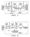
- Figure 1 is a schematic diagram of a known power supply apparatus in a portable radio telephone,
- Figure 2 is a schematic diagram of a power supply apparatus in a portable radio telephone, in accordance with one embodiment of the invention, given by way of example,
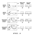
- Figure 3 is a table showing graphic representations of control elements in the apparatus of Figure 2 in different functional states, and
- Figure 4 is a table showing the functional states of control elements in the apparatus of Figure 2 in different operational conditions of the apparatus, using the graphic representations of Figure 3.
-
- Figure 1 shows a portable radio communication apparatus, in this example a
portable radio telephone 1. Theportable telephone 1 comprises a communication module including active signal processing, memory and audio circuits forming aload 2 energised by a power supply applying a voltage to aterminal 3 of the load. The power supply includes arechargeable battery 4 connected to aterminal 5 for supplying power to theload 2 during normal usage of thetelephone 1. - The power supply also comprises a
charger 6 in the form of a voltage generator that may be connected to aterminal 7 of thetelephone 1 to charge thebattery 4 and, if necessary, to power theload 2. Typically, the charger is an AC/DC converter but it may alternatively be a DC/DC transformer, for example. Thecharger 6 supplies power to thebattery 4 along acharging path 8 to a connection point 9 connected with thebattery terminal 5 through acurrent sensing resistor 10. The connection point 9 is connected to theload terminal 3 through a blocking control element 11 whose function is described below. The control element and other control elements described below are operated under the control ofmicrocontroller unit 12. - The
charger terminal 7 is connected to thecharging path 8 in series through a clamp control element 13 to aconnection point 14. Thecharging path 8 then includes in series acharge control element 15, a reverse currentblocking control element 16 and acurrent sense resistor 17. - The control elements are discrete field-effect transistors ('FETs') and, in this example are unidirectional FETs. As illustrated by the symbol of a diode, the FETs allow a parasitic current to flow even when subjected to a reverse voltage.
- In operation, with the
charger 6 disconnected, thebattery 4 supplies power through thecurrent sensing resistor 10 and the blocking control element 11 to theterminal 3 and theload 2, the blocking control element 11 being biased to a conducting state by theMCU 12. - When the
charger 6 is connected, in normal charging conditions, the charger supplies power through thecharging path 8 to the connection point 9, the charging current being controlled by the MCU through thecharge control element 15 in dependence on the voltages and currents sensed. - If the
charger 6 is connected to theterminal 7 before being energised and power is then applied, the voltage at theterminal 7 can be excessive. This condition is monitored by theMCU 12 and regulated through the clamp control element 13. - If the charger is unplugged (de-energised) while still connected to the
terminal 7 with thebattery 4 charged, theMCU 12 switches the reverse currentblocking control element 16 to a non-conductive state to prevent the flow of reverse current into thecharger 6. - If the
battery 4 is at a low state of charge, thecharger 6 is able to supply sufficient power to operate the active circuits of theload 2. However, if the state of charge of thebattery 4 is too low, the charger cannot raise the voltage at theterminal 3 to a sufficient level to operate the active circuits of theload 2 until thebattery 4 has charged at least partially; this can take several minutes, during which time the telephone is unusable. Accordingly, asupply path 18 is provided in parallel with thecharging path 8 to enable thecharger 6 to supply power directly to theterminal 3 and theload 2. Ablocking control element 19 is connected in series in theparallel path 18 and theMCU 12 normally maintains theblocking control element 19 non-conducting and the blocking control element 11 conducting so that the power supply and charging currents from thecharger 6 pass along thepath 8 and are controlled by thecontrol elements 15 to 17. However, when theMCU 12 senses that the battery voltage is too low, it makes theblocking control element 19 conducting and the blocking control element 11 non-conducting, so that thecharger 6 supplies power to theterminal 3 and theload 2 along thepath 18 and thebattery 4 is disconnected from theterminal 3 so as not to drag down the voltage at the terminal while the battery is still discharged. - The voltage supply apparatus shown in Figure 1 fulfils the basic function of enabling the
charger 6 to power theload 2 with adead battery 4 or with thebattery 4 removed but it requires 5 discrete control components, which adds cost to the telephone, and in addition, these components occupy space on the circuit board, which further increases the cost of ensuring dead battery operation. - The voltage supply apparatus of the embodiment of the present invention is able to provide dead or missing battery operation with fewer components, comparable with the number of components in a telephone incapable of dead battery operation, so that the dead or missing battery operation feature involves substantially no on-cost.
- In Figure 2, elements that are similar to those of Figure 1 bear similar reference numbers. The
charger terminal 7 is connected to the connection point 9 through acharging path 8. Theload terminal 3 is connected directly to the connection point 9. TheMCU 12 controls the charging current in, and the voltage applied to thepath 8 through a clamp andcharge control element 20 in series in thepath 8, reverse current being controlled by theblocking element 16. A blocking andcharge control element 21 is connected in series with thecurrent sense resistor 10 between thebattery terminal 5 and the connection point 9. - The charging clamp and
charge control element 20 and the battery clamp andcharge control element 21 are controlled by theMCU 12 to present a high impedance, non-conductive state or a low impedance, conductive state or a controlled impedance state in which their impedance is controlled as a function of the sensed current and/or voltage variables. - In operation, with the
charger 6 disconnected, thebattery 4 supplies power through theblocking control element 21 and thecurrent sensing resistor 10 to theterminal 3 and theload 2, theblocking control element 21 being biased to a conducting state by theMCU 12. - When the
charger 6 is connected, in normal charging conditions, the charger supplies power through thecharging path 8 to the connection point 9, the charging current being controlled by the MCU through thecharge control elements battery 4 instead of theload 2 is controlled by thecharge control element 21. - If the
charger 6 is connected to theterminal 7 before being energised and power is then applied, the voltage at theterminal 7 is regulated by theMCU 12 through theclamp control element 20. - If the charger is unplugged (de-energised) while still connected to the
terminal 7 with thebattery 4 charged, theMCU 12 switches the reverse currentblocking control element 16 to a non-conductive state to prevent the flow of reverse current into thecharger 6. - If the
battery 4 is at a low state of charge, thecharger 6 is able to supply sufficient power to operate the active circuits of theload 2. However, if the state of charge of thebattery 4 is too low, the blocking andcharge control element 21 connected in series between thebattery terminal 5 and the connection point 9 is rendered non-conducting by theMCU 12, so that thecharger 6 supplies power to theterminal 3 and theload 2 with thebattery 4 disconnected from the connection point 9 so as not to drag down the voltage at the terminal if the battery is totally discharged; the battery can charge over thepath 8 even while thecharger 6 supplies power to theload 2 if the charger power supply is sufficient, theMCU 12 putting the blocking andcharge control element 21 in an intermediate impedance state such that the voltage at the connection point 9 and theload terminal 3 is higher than the voltage at thebattery terminal 5. - When the
battery 4 is partially charged to a battery voltage less than full charge, the telephone can be used with power supplied from thecharger 6 over thepath 8 while the battery is charging. TheMCU 12 puts the clamp andcharge control element 20 and the blocking andcharge control element 21 in the intermediate, controlled impedance state or a fully conductive state, according to the power supply conditions so that thecharger 6 supplies appropriate current both to the battery and to the load. - In one embodiment of the invention, when the
battery 4 reaches full charge, theMCU 12 puts the clamp andcharge control element 20 into its non-conductive state, so as to disconnect thecharger 6 from theload 2 and thebattery 4. - In another embodiment of the invention, when the
battery 4 is at full charge with the charger connected, theMCU 12 puts the blocking andcharge control element 21 into its non-conductive state, so as to disconnect thebattery 4 from theload 2 and thecharger 6, so as to leave thebattery 4 in its fully charged condition during use of the telephone. - The
control elements control element 20 may be a bidirectional FET. It is also possible for theblocking control element 16 to be a diode. Thecontrol element 21 is preferably a unidirectional FET. - The operation of this embodiment of the invention will now be described in more detail with reference to Figures 3 and 4 of the drawings. Figure 3 shows the simplified symbols used in Figure 4 to represent the different operational states of the
control elements control element 22 in a non-conductive state is represented as a single open switch in the case of asingle FET 23 or a dual open switch in the case of a dual FET 24. A control element 25 in a fully conductive state is represented as a single closed switch in the case of asingle FET 26 or a dual closed switch in the case of adual FET 27. A control element 28 in a voltage regulating state is represented by a voltage limiting symbol in the case of asingle FET 29 or a voltage limiting symbol in series with a closed switch in the case of adual FET 30. A control element 31 in a current regulating state is represented by an arrow in the case of asingle FET 32 or an arrow in series with a closed switch in the case of adual FET 33. - Figure 4 shows the operating states of the
control elements - When no
charger 6 is connected, theMCU 12 puts both thecontrol elements control element 21 either non-conductive (A) if theload 2 is not being used or conductive (B) if it is. - When a low- or high-
power charger 6 is connected, theMCU 12 puts the charging clamp andcharge control element 20 in the voltage clamp state and the blockingelement 16 conductive. If there is nobattery 4 connected (C), theMCU 12 puts thecontrol element 21 non-conductive. If thebattery 4 is connected (D), theMCU 12 puts thecontrol element 21 in current-regulated state to conduct 'trickle' current, enabling theload 2 to operate at full voltage while still charging thebattery 4, albeit slowly. - When a low-
power charger 6 is connected with an at least partially chargedbattery 4 connected, theMCU 12 puts thecontrol element 20 in current-regulated state, with the blockingelement 16 conductive, for a normally low battery (E), the current being reduced by thecontrol element 20 during 'top-off' when thebattery 4 is close to full charge (G); in each case, thecontrol element 21 is conductive so that thebattery 4 can charge while theload 2 is operating under power supplied from the charger. Whenbattery 4 is fully charged (I), theMCU 12 puts thecontrol element 20 and the blockingelement 16 non-conductive, thecontrol element 21 being conductive so that thebattery 4 supplies theload 2. - When a high-
power charger 6 is connected with an at least partially chargedbattery 4 connected, theMCU 12 puts thecontrol element 20 in current-regulated state, with the blockingelement 16 conductive, for a normally low battery (F), the current being reduced by thecontrol element 21 during 'top-off' when thebattery 4 is close to full charge (H), in which case, thecontrol element 20 is in voltage-regulation state. Whenbattery 4 is fully charged (J), theMCU 12 puts thecontrol element 21 non-conductive, thecontrol element 21 being in voltage-regulation state and the blockingelement 16 being conductive so that thecharger 6 supplies theload 2 and preserves the charge of thebattery 4.
Claims (10)
- Power supply apparatus for supplying a direct voltage to a load (2) that is connected to a first terminal (3), the supply apparatus comprising a rechargeable battery (4) for connection to a second terminal (5), and a voltage generator (6) for recharging said battery (4) and supplying power to said load (2),
characterised by first control means (20, 16) for controlledly supplying current from said voltage generator (6) to said first terminal (3) so as to control supply of current from said voltage generator (6) to said load (2) and for preventing reverse flow of current from said first terminal (3) to said voltage generator (6), and
second control means (21) for controlledly supplying current between said first (3) and second (5) terminals so as to control supply of current from said voltage generator (6) through said first control means (20, 16) to said battery (4) and from said battery to said load (2). - Power supply apparatus as claimed in claim 1, wherein said control means (20, 16; 21) present selectively a high impedance state (23), a low impedance state (26) or a controlled impedance state (29, 32).
- Power supply apparatus as claimed in claim 2 wherein said second control means (21) is responsive to the presence of a low battery voltage at said second terminal (5) to present said controlled impedance state between said first (3) and second (5) terminals so as to apply a controlled voltage at said first terminal (3) greater than said low battery voltage.
- Power supply apparatus as claimed in claim 2 or 3 wherein said control means (20, 16; 21) are responsive to a battery voltage less than full charge to present said controlled impedance state so that said voltage generator (6) supplies current both to said battery (4) and to said load (2).
- Power supply apparatus as claimed in any of claims 2 to 4 wherein said first control means (20, 16) is responsive to a battery voltage substantially equal to full charge to present said high impedance state so as to disconnect said voltage generator (6) from said battery (4) and said load (2).
- Power supply apparatus as claimed in any of claims 2 to 4 wherein said second control means (21) is responsive to a battery voltage substantially equal to full charge to present said high impedance state so as to disconnect said battery (4) from said voltage generator (6) and said load (2).
- Power supply apparatus as claimed in any of claims 2 to 6 wherein said control means comprises field-effect transistors and means (12) for controlling said field-effect transistors to present selectively said high impedance state, said low impedance state or said controlled impedance state.
- Power supply apparatus as claimed in claim 7 wherein said first control means (20, 16) comprises at least a first one (21) of said field-effect transistors connected in series between said voltage generator (6) and said first terminal (3) for controlling supply of current from said voltage generator (6) to said first terminal (3) and a second element (16) connected in series between said voltage generator (6) and said first terminal (3) for preventing reverse flow of current from said first terminal (3) to said voltage generator (6).
- Power supply apparatus as claimed in claim 8 wherein said second element (16) comprises a second one of said field-effect transistors.
- Portable radio communication apparatus comprising a communication module and power supply apparatus as claimed in any preceding claim for supplying power to said communication module as said load.
Priority Applications (8)
| Application Number | Priority Date | Filing Date | Title |
|---|---|---|---|
| EP03292409A EP1521344A1 (en) | 2003-09-30 | 2003-09-30 | Power supply apparatus |
| EP04787045A EP1671410A1 (en) | 2003-09-30 | 2004-09-29 | Power supply apparatus |
| JP2006530039A JP2007507994A (en) | 2003-09-30 | 2004-09-29 | Power supply |
| KR1020067006248A KR20060089223A (en) | 2003-09-30 | 2004-09-29 | Power supply |
| PCT/EP2004/010875 WO2005039015A1 (en) | 2003-09-30 | 2004-09-29 | Power supply apparatus |
| US10/595,228 US7482781B2 (en) | 2003-09-30 | 2004-09-29 | Controlling power supply between a voltage generator, a load and a rechargeable battery |
| CN2004800282604A CN1860657B (en) | 2003-09-30 | 2004-09-29 | power supply unit |
| TW093129647A TW200524246A (en) | 2003-09-30 | 2004-09-30 | Power supply apparatus |
Applications Claiming Priority (1)
| Application Number | Priority Date | Filing Date | Title |
|---|---|---|---|
| EP03292409A EP1521344A1 (en) | 2003-09-30 | 2003-09-30 | Power supply apparatus |
Publications (1)
| Publication Number | Publication Date |
|---|---|
| EP1521344A1 true EP1521344A1 (en) | 2005-04-06 |
Family
ID=34307011
Family Applications (2)
| Application Number | Title | Priority Date | Filing Date |
|---|---|---|---|
| EP03292409A Withdrawn EP1521344A1 (en) | 2003-09-30 | 2003-09-30 | Power supply apparatus |
| EP04787045A Withdrawn EP1671410A1 (en) | 2003-09-30 | 2004-09-29 | Power supply apparatus |
Family Applications After (1)
| Application Number | Title | Priority Date | Filing Date |
|---|---|---|---|
| EP04787045A Withdrawn EP1671410A1 (en) | 2003-09-30 | 2004-09-29 | Power supply apparatus |
Country Status (7)
| Country | Link |
|---|---|
| US (1) | US7482781B2 (en) |
| EP (2) | EP1521344A1 (en) |
| JP (1) | JP2007507994A (en) |
| KR (1) | KR20060089223A (en) |
| CN (1) | CN1860657B (en) |
| TW (1) | TW200524246A (en) |
| WO (1) | WO2005039015A1 (en) |
Cited By (5)
| Publication number | Priority date | Publication date | Assignee | Title |
|---|---|---|---|---|
| GB2416606A (en) * | 2004-07-26 | 2006-02-01 | Wolfson Microelectronics Plc | Power supply circuit for portable battery powered device |
| US7402986B2 (en) | 2004-07-26 | 2008-07-22 | Wolfson Microelectronics Plc | Power supply circuit for portable battery powered device |
| FR2916578A1 (en) * | 2007-05-25 | 2008-11-28 | Saft Groupe Sa | ELECTRONIC SYSTEM FOR BATTERY. |
| EP1772942A3 (en) * | 2005-10-04 | 2010-09-15 | O2Micro, Inc. | Battery charge/discharge control circuit |
| CN105634048A (en) * | 2014-11-05 | 2016-06-01 | 矽统科技股份有限公司 | Electric quantity management device and electric quantity management method |
Families Citing this family (6)
| Publication number | Priority date | Publication date | Assignee | Title |
|---|---|---|---|---|
| JP2007181263A (en) * | 2005-12-27 | 2007-07-12 | Kyocera Corp | Charger |
| US7675269B2 (en) * | 2006-11-03 | 2010-03-09 | Broadcom Corporation | Circuit and method for battery charging and discharging protection |
| US8994341B2 (en) | 2009-06-29 | 2015-03-31 | Freescale Semiconductor, Inc. | Battery charging circuit and electronic device |
| TWI396360B (en) * | 2010-06-04 | 2013-05-11 | 通嘉科技股份有限公司 | Power path management circuit and method |
| US9692248B2 (en) * | 2013-03-14 | 2017-06-27 | Blackberry Limited | Positioning aid for wireless energy transfer |
| JP2023079064A (en) * | 2021-11-26 | 2023-06-07 | パナソニックIpマネジメント株式会社 | backup power system |
Citations (4)
| Publication number | Priority date | Publication date | Assignee | Title |
|---|---|---|---|---|
| GB2243961A (en) * | 1990-03-09 | 1991-11-13 | Sunleigh Electrical Developmen | DC-DC Power supply circuit |
| EP0695017A2 (en) * | 1994-07-26 | 1996-01-31 | International Business Machines Corporation | Battery connecting device for a computer and a method of switching batteries |
| US6002220A (en) * | 1996-08-22 | 1999-12-14 | Hitachi, Ltd. | Electric power storage air-conditioning system |
| US20020135235A1 (en) * | 2001-03-22 | 2002-09-26 | Winick Bradley D. | Active circuit protection for switched power supply system |
-
2003
- 2003-09-30 EP EP03292409A patent/EP1521344A1/en not_active Withdrawn
-
2004
- 2004-09-29 EP EP04787045A patent/EP1671410A1/en not_active Withdrawn
- 2004-09-29 CN CN2004800282604A patent/CN1860657B/en not_active Expired - Fee Related
- 2004-09-29 WO PCT/EP2004/010875 patent/WO2005039015A1/en not_active Ceased
- 2004-09-29 JP JP2006530039A patent/JP2007507994A/en active Pending
- 2004-09-29 US US10/595,228 patent/US7482781B2/en not_active Expired - Fee Related
- 2004-09-29 KR KR1020067006248A patent/KR20060089223A/en not_active Ceased
- 2004-09-30 TW TW093129647A patent/TW200524246A/en unknown
Patent Citations (4)
| Publication number | Priority date | Publication date | Assignee | Title |
|---|---|---|---|---|
| GB2243961A (en) * | 1990-03-09 | 1991-11-13 | Sunleigh Electrical Developmen | DC-DC Power supply circuit |
| EP0695017A2 (en) * | 1994-07-26 | 1996-01-31 | International Business Machines Corporation | Battery connecting device for a computer and a method of switching batteries |
| US6002220A (en) * | 1996-08-22 | 1999-12-14 | Hitachi, Ltd. | Electric power storage air-conditioning system |
| US20020135235A1 (en) * | 2001-03-22 | 2002-09-26 | Winick Bradley D. | Active circuit protection for switched power supply system |
Cited By (8)
| Publication number | Priority date | Publication date | Assignee | Title |
|---|---|---|---|---|
| GB2416606A (en) * | 2004-07-26 | 2006-02-01 | Wolfson Microelectronics Plc | Power supply circuit for portable battery powered device |
| US7402986B2 (en) | 2004-07-26 | 2008-07-22 | Wolfson Microelectronics Plc | Power supply circuit for portable battery powered device |
| GB2416606B (en) * | 2004-07-26 | 2009-04-22 | Wolfson Microelectronics Plc | Power supply circuit for portable battery powered device |
| EP1772942A3 (en) * | 2005-10-04 | 2010-09-15 | O2Micro, Inc. | Battery charge/discharge control circuit |
| FR2916578A1 (en) * | 2007-05-25 | 2008-11-28 | Saft Groupe Sa | ELECTRONIC SYSTEM FOR BATTERY. |
| US7834590B2 (en) | 2007-05-25 | 2010-11-16 | Saft Groupe Sa | Electronic system for a battery |
| CN105634048A (en) * | 2014-11-05 | 2016-06-01 | 矽统科技股份有限公司 | Electric quantity management device and electric quantity management method |
| CN105634048B (en) * | 2014-11-05 | 2018-07-17 | 矽统科技股份有限公司 | Electric quantity management device and electric quantity management method |
Also Published As
| Publication number | Publication date |
|---|---|
| EP1671410A1 (en) | 2006-06-21 |
| CN1860657B (en) | 2010-11-24 |
| KR20060089223A (en) | 2006-08-08 |
| CN1860657A (en) | 2006-11-08 |
| US20070063674A1 (en) | 2007-03-22 |
| TW200524246A (en) | 2005-07-16 |
| JP2007507994A (en) | 2007-03-29 |
| WO2005039015A1 (en) | 2005-04-28 |
| US7482781B2 (en) | 2009-01-27 |
Similar Documents
| Publication | Publication Date | Title |
|---|---|---|
| KR100254478B1 (en) | Charging and discharging control device | |
| US9716403B2 (en) | Battery charger circuit for changing between modes during operation based on temperature and battery voltage and method therefor | |
| US8193779B2 (en) | Battery charging and discharging by using a bi-directional transistor | |
| US5177426A (en) | Over-discharge protection circuitry | |
| US20040108839A1 (en) | Electrical energy apparatuses, electrical energy conditioning circuits, and electrical energy supply methods | |
| EP1867215A1 (en) | A power supply | |
| US8958220B2 (en) | Power-saving voltage converter operation | |
| US9231417B2 (en) | Rechargeable electrical device | |
| JPH04229032A (en) | Electric system for supplying power to load | |
| US7482781B2 (en) | Controlling power supply between a voltage generator, a load and a rechargeable battery | |
| SE515882C2 (en) | Electrical power management system and radio communication device comprising such a system | |
| CN101120618A (en) | power supply | |
| US8154247B2 (en) | Portable telecommunications device | |
| US6621248B1 (en) | Charging device with selectable output voltage values | |
| US20050110462A1 (en) | Power charger and rechargeable battery system | |
| JP2003079058A (en) | Battery pack | |
| JPH0766772A (en) | Portable radios and power supplies | |
| CN112910065B (en) | Charging circuit, electrical equipment and charger | |
| US20040177282A1 (en) | Method and circuit for controlling battery charge and supply by microprocessor | |
| JP2002320333A (en) | Electronic equipment with charging function | |
| JP2004173351A (en) | Power circuit | |
| JPH053676A (en) | Power control device | |
| JP2000069681A (en) | Power supply adapter, electronic equipment and power supply system | |
| JPH1051966A (en) | Automatic battery charger | |
| JPH06253471A (en) | Electrical apparatus with floating charging power-supply |
Legal Events
| Date | Code | Title | Description |
|---|---|---|---|
| PUAI | Public reference made under article 153(3) epc to a published international application that has entered the european phase |
Free format text: ORIGINAL CODE: 0009012 |
|
| AK | Designated contracting states |
Kind code of ref document: A1 Designated state(s): AT BE BG CH CY CZ DE DK EE ES FI FR GB GR HU IE IT LI LU MC NL PT RO SE SI SK TR |
|
| AX | Request for extension of the european patent |
Extension state: AL LT LV MK |
|
| AKX | Designation fees paid | ||
| REG | Reference to a national code |
Ref country code: DE Ref legal event code: 8566 |
|
| STAA | Information on the status of an ep patent application or granted ep patent |
Free format text: STATUS: THE APPLICATION IS DEEMED TO BE WITHDRAWN |
|
| 18D | Application deemed to be withdrawn |
Effective date: 20051007 |