EP1521264A2 - Disc cartridge - Google Patents
Disc cartridge Download PDFInfo
- Publication number
- EP1521264A2 EP1521264A2 EP04023402A EP04023402A EP1521264A2 EP 1521264 A2 EP1521264 A2 EP 1521264A2 EP 04023402 A EP04023402 A EP 04023402A EP 04023402 A EP04023402 A EP 04023402A EP 1521264 A2 EP1521264 A2 EP 1521264A2
- Authority
- EP
- European Patent Office
- Prior art keywords
- inner shell
- shell
- portions
- aperture
- disc
- Prior art date
- Legal status (The legal status is an assumption and is not a legal conclusion. Google has not performed a legal analysis and makes no representation as to the accuracy of the status listed.)
- Withdrawn
Links
- 239000000463 material Substances 0.000 claims abstract description 34
- 239000007769 metal material Substances 0.000 claims abstract description 8
- 229920003023 plastic Polymers 0.000 claims abstract description 8
- 239000004033 plastic Substances 0.000 claims abstract description 8
- 230000003287 optical effect Effects 0.000 abstract description 58
- 230000007613 environmental effect Effects 0.000 abstract description 13
- 230000002093 peripheral effect Effects 0.000 description 39
- 230000000903 blocking effect Effects 0.000 description 16
- 230000008595 infiltration Effects 0.000 description 14
- 238000001764 infiltration Methods 0.000 description 14
- 239000000428 dust Substances 0.000 description 13
- 238000003780 insertion Methods 0.000 description 8
- 230000037431 insertion Effects 0.000 description 7
- 238000005259 measurement Methods 0.000 description 6
- 238000010521 absorption reaction Methods 0.000 description 5
- XLYOFNOQVPJJNP-UHFFFAOYSA-N water Substances O XLYOFNOQVPJJNP-UHFFFAOYSA-N 0.000 description 5
- 239000000945 filler Substances 0.000 description 4
- 239000011521 glass Substances 0.000 description 4
- 229920000515 polycarbonate Polymers 0.000 description 4
- 239000004417 polycarbonate Substances 0.000 description 4
- 238000012360 testing method Methods 0.000 description 4
- 229910000838 Al alloy Inorganic materials 0.000 description 3
- 239000004696 Poly ether ether ketone Substances 0.000 description 3
- 230000007423 decrease Effects 0.000 description 3
- 229920002530 polyetherether ketone Polymers 0.000 description 3
- 229920001955 polyphenylene ether Polymers 0.000 description 3
- 230000001105 regulatory effect Effects 0.000 description 3
- 239000000057 synthetic resin Substances 0.000 description 3
- 229920003002 synthetic resin Polymers 0.000 description 3
- 238000003466 welding Methods 0.000 description 3
- 239000004962 Polyamide-imide Substances 0.000 description 2
- 239000004695 Polyether sulfone Substances 0.000 description 2
- 239000004697 Polyetherimide Substances 0.000 description 2
- 239000004642 Polyimide Substances 0.000 description 2
- 235000005811 Viola adunca Nutrition 0.000 description 2
- 240000009038 Viola odorata Species 0.000 description 2
- 235000013487 Viola odorata Nutrition 0.000 description 2
- 235000002254 Viola papilionacea Nutrition 0.000 description 2
- 229920000122 acrylonitrile butadiene styrene Polymers 0.000 description 2
- XAGFODPZIPBFFR-UHFFFAOYSA-N aluminium Chemical compound [Al] XAGFODPZIPBFFR-UHFFFAOYSA-N 0.000 description 2
- 229910052782 aluminium Inorganic materials 0.000 description 2
- 238000010276 construction Methods 0.000 description 2
- 229920005669 high impact polystyrene Polymers 0.000 description 2
- 239000004797 high-impact polystyrene Substances 0.000 description 2
- 238000000465 moulding Methods 0.000 description 2
- 229920002492 poly(sulfone) Polymers 0.000 description 2
- -1 polyallylate Polymers 0.000 description 2
- 229920002312 polyamide-imide Polymers 0.000 description 2
- 229920006393 polyether sulfone Polymers 0.000 description 2
- 229920001601 polyetherimide Polymers 0.000 description 2
- 229920001721 polyimide Polymers 0.000 description 2
- 229920006324 polyoxymethylene Polymers 0.000 description 2
- 238000003825 pressing Methods 0.000 description 2
- 230000002265 prevention Effects 0.000 description 2
- 230000003449 preventive effect Effects 0.000 description 2
- 229920005989 resin Polymers 0.000 description 2
- 239000011347 resin Substances 0.000 description 2
- 230000000717 retained effect Effects 0.000 description 2
- 238000007789 sealing Methods 0.000 description 2
- 239000010935 stainless steel Substances 0.000 description 2
- 229910001220 stainless steel Inorganic materials 0.000 description 2
- 102100034176 Glutathione-specific gamma-glutamylcyclotransferase 1 Human genes 0.000 description 1
- 101710175495 Glutathione-specific gamma-glutamylcyclotransferase 1 Proteins 0.000 description 1
- 229910001209 Low-carbon steel Inorganic materials 0.000 description 1
- 229930182556 Polyacetal Natural products 0.000 description 1
- XECAHXYUAAWDEL-UHFFFAOYSA-N acrylonitrile butadiene styrene Chemical compound C=CC=C.C=CC#N.C=CC1=CC=CC=C1 XECAHXYUAAWDEL-UHFFFAOYSA-N 0.000 description 1
- 239000004676 acrylonitrile butadiene styrene Substances 0.000 description 1
- 238000013459 approach Methods 0.000 description 1
- 230000000052 comparative effect Effects 0.000 description 1
- 230000001747 exhibiting effect Effects 0.000 description 1
- 238000001746 injection moulding Methods 0.000 description 1
- 239000000696 magnetic material Substances 0.000 description 1
- 238000000034 method Methods 0.000 description 1
- 230000000704 physical effect Effects 0.000 description 1
- 230000000630 rising effect Effects 0.000 description 1
Images








Classifications
-
- G—PHYSICS
- G11—INFORMATION STORAGE
- G11B—INFORMATION STORAGE BASED ON RELATIVE MOVEMENT BETWEEN RECORD CARRIER AND TRANSDUCER
- G11B23/00—Record carriers not specific to the method of recording or reproducing; Accessories, e.g. containers, specially adapted for co-operation with the recording or reproducing apparatus ; Intermediate mediums; Apparatus or processes specially adapted for their manufacture
- G11B23/02—Containers; Storing means both adapted to cooperate with the recording or reproducing means
- G11B23/03—Containers for flat record carriers
- G11B23/0301—Details
- G11B23/0308—Shutters
-
- G—PHYSICS
- G11—INFORMATION STORAGE
- G11B—INFORMATION STORAGE BASED ON RELATIVE MOVEMENT BETWEEN RECORD CARRIER AND TRANSDUCER
- G11B23/00—Record carriers not specific to the method of recording or reproducing; Accessories, e.g. containers, specially adapted for co-operation with the recording or reproducing apparatus ; Intermediate mediums; Apparatus or processes specially adapted for their manufacture
- G11B23/02—Containers; Storing means both adapted to cooperate with the recording or reproducing means
- G11B23/03—Containers for flat record carriers
- G11B23/0301—Details
- G11B23/0313—Container cases
- G11B23/0315—Materials
-
- G—PHYSICS
- G11—INFORMATION STORAGE
- G11B—INFORMATION STORAGE BASED ON RELATIVE MOVEMENT BETWEEN RECORD CARRIER AND TRANSDUCER
- G11B23/00—Record carriers not specific to the method of recording or reproducing; Accessories, e.g. containers, specially adapted for co-operation with the recording or reproducing apparatus ; Intermediate mediums; Apparatus or processes specially adapted for their manufacture
- G11B23/02—Containers; Storing means both adapted to cooperate with the recording or reproducing means
- G11B23/03—Containers for flat record carriers
- G11B23/0301—Details
- G11B23/0307—Positioning or centering features
-
- G—PHYSICS
- G11—INFORMATION STORAGE
- G11B—INFORMATION STORAGE BASED ON RELATIVE MOVEMENT BETWEEN RECORD CARRIER AND TRANSDUCER
- G11B23/00—Record carriers not specific to the method of recording or reproducing; Accessories, e.g. containers, specially adapted for co-operation with the recording or reproducing apparatus ; Intermediate mediums; Apparatus or processes specially adapted for their manufacture
- G11B23/02—Containers; Storing means both adapted to cooperate with the recording or reproducing means
- G11B23/03—Containers for flat record carriers
- G11B23/0301—Details
- G11B23/0312—Driving features
Definitions
- the present invention relates to a disc cartridge in which an interior of a shell unit accommodates a disc-shaped recording medium and an inner shell.
- a Blu-ray disc classified as an optical disc having a higher recording density than that of a DVD has recently been utilized by way of an optical recording medium.
- a spot diameter (spot size) of a laser beam is by far smaller, and consequently dusts, flaws, etc. are easy to affect recording and reproducing. Therefore, a cartridge for the Blu-ray disc as disclosed in Japanese Patent Application Laid-Open Publication No.2003-109352 tries to increase a sealing degree by providing an inner shell in addition to a normal shell unit of the cartridge in order to prevent ambient dusts from entering the cartridge.
- the sealing degree of the cartridge is increased, the cartridge, if it deforms, becomes easy to abut on the disc.
- a plastic material normally used for forming the cartridge member warps, with the result that the cartridge is brought into contact with the disc.
- a disc cartridge includes a shell unit for accommodating a disc-shaped recording medium rotatably and in a shielded state, and an inner shell disposed in an interior of the shell unit and including a ring portion so protruded to an outer periphery as to form a space where the disc-shaped recording medium exists, wherein the inner shell is made of a metallic material or of a heat resistant plastic material of which a deflection temperature under load is equal to or higher than 135°C, preferably 150°C so that the inner shell exhibits heat resistance and its deformation becomes small.
- the inner shell forming the space where the disc-shaped recording medium exists is made of the material exhibiting the heat resistance and the small degree of deformation. It is therefore feasible to restrain the deformation of the inner shell even when the environmental change occurs and to prevent the contact between the disc-shaped recording medium and the cartridge.
- polyamide-imide, polyallylate, polycarbonate, polyether ether ketone, polyetherimide, polyether sulfone, polyimide, polyphenylene ether and polysulfone are preferable to materials of the inner shell.
- each of polycarbonate, polyether ether ketone and polyphenylene ether has a low percentage of water absorption equal to or smaller than 0.2%, and has a merit against a change in humidity.
- plastic materials other than these materials can be used by their being filled with 10% through 30% of filler such as glass, etc..
- light-weight metallic materials such as aluminum and an aluminum alloy are preferable as the metallic materials.
- the deflection temperature under load in this specification is a value at 1.80 MPa based on a load-deflection temperature testing method according to ISO75. The warp of the cartridge itself along with an abrupt change in temperature is thus measured, and the deflection temperature under load is obtained, whereby a material proper to the inner shell can be selected.
- a ring-shaped member having an outside diameter slightly larger than an outer periphery of the disc-shaped recording medium is fitted in the vicinity of a root portion of the ring portion of the inner shell, thereby enabling effective restraint of the deformation of the inner shell.
- the contact between the cartridge and the disc-shaped recording medium can be prevented by causing none of the deformation of the inner shell. Particularly, it is possible to prevent the contact therebetween by retaining the cartridge while causing no change in the configuration of the ring portion of the inner shell even when the abrupt environmental change occurs.
- materials each having a load-deflection temperature (1.80 MPa) higher than 135°C be used as materials of the inner shell and of the ring-shaped member of the inner shell in order to prevent the deformation caused by the temperature change.
- materials each having a percentage of water absorption is smaller than 0.2% (23°C, 24 hours) be employed for preventing the deformation of the cartridge due to a change in humidity.
- the disc cartridge can take such a configuration that the shell unit has a first aperture, and the inner shell has a second aperture taking substantially the same shape as the first aperture, the disc cartridge further includes a shutter disposed between the shell unit and the inner shell, and the first aperture is opened and closed by rotating the inner shell relatively to the shutter and the shell unit.
- the disc cartridge in the present embodiment it is feasible to prevent the contact between the disc-shaped recording medium and the cartridge even when the environmental change occurs in the structure that the interior of the shell unit is provided with the inner shell.
- FIG. 1 is a perspective view showing the disc cartridge as viewed from the side of an upper shell.
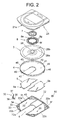
- FIG. 2 is an exploded perspective view of FIG. 1.
- FIG. 3 is a perspective view showing the disc cartridge in a shutter-closed state as viewed from the side of a lower shell.
- FIG. 4 is an exploded perspective view of FIG. 3.
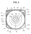
- FIG. 5 is a view showing an inner surface of the upper shell in FIG. 4.
- FIG. 6 is a view showing an inner surface of the lower shell in FIG. 2.
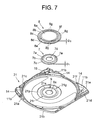
- FIG. 7 is a perspective view showing the upper shell, a clamp member and a clamp presser member.
- FIG. 8 is a sectional view of the disc cartridge as viewed by cutting it in a direction along the line VIII-VIII in FIG. 1.
- FIG. 9 is a sectional view of the disc cartridge as viewed by cutting it in a direction along the line IX-IX in FIG. 3.
- a disc cartridge 1 includes a cartridge box body 2, an inner shell 4 and a shutter unit 5.
- the cartridge box body 2 accommodates an optical disc 3 in a rotatable manner, and has an upper shell 2 and a lower shell 22 formed with a first aperture portion 6 for recording and reproducing.
- the cartridge box body 2 is constructed by superimposing a peripheral wall 21a of the upper shell 21 on a peripheral wall 22a of the lower shell 22, and accommodates the optical disc 3, the inner shell 4 and the shutter unit 5.
- the inner shell 4 has a second aperture portion 42 taking substantially the same shape as the first aperture portion 6, and the shutter unit 5 is connected to the inner shell 4 and opens and closes the first aperture portion 6.
- the shutter unit 5 moves to a first position in which to close the first aperture portion 6 formed in the cartridge box body 2.
- the shutter unit 5 moves to a second position in which to open the first aperture portion 6 formed in the cartridge box body 2.
- a clamp member 7 is so secured by the clamp presser member 8 to the inner surface of the upper shell 21 as to be movable in vertical directions.
- the clamp member 7 is magnetically attracted toward a turntable of the recording/reproducing apparatus.
- the clamp member 7 pinches the optical disc 3 between the turntable of the recording/reproducing apparatus and the clamp member 7 itself, and then clamps the optical disc 3 down.
- the upper shell 21 is structured of a member taking a rectangular shape with a front sided portion formed in a circular arc or substantially a square shape.
- An outer peripheral edge portion of the upper shell 21 is provided with the peripheral wall 21a, and a first recessed portion 21p for fitting the clamp member 7 is formed in a central portion of the inner surface of the upper shell 21.
- the first recessed portion 21p includes first and second alignment (positioning) pins 21q, 21r inserted into first and second alignment pin insertion holes 8e, 8f formed in a fixing portion 8d of the clamp presser member 8.
- the first and second alignment pins 21q, 21r are formed by resin molding integrally with the upper shell 21, corresponding to the first and second alignment pin insertion holes 8e, 8f of the clamp presser member 8.
- a second recessed portion 21s into which a collar portion 7c of the clamp member 7 is inserted, is formed along an inner periphery of the first recessed portion 21p in the inner surface of the upper shell 21.
- a central portion of the clamp member movement regulating portion 9 is formed with a recessed portion 9a into which an upper face side of the recessed portion 7d of the clamp member 7 is inserted.
- the peripheral wall 21a of the upper shell 21 has a front edge portion 21b, a pair of side edge portions 21c, 21d and a rear edge portion 21e.
- a central portion of the rear edge portion 21e is formed with an alignment recessed portion 21f for alignment with the lower shell 22.
- first dust-proof walls 11a at a corner portion between the front side edge portion 21b and one side edge portion 21c, at a corner portion between one side edge portion 21c and the rear side edge portion 21e, and at a corner portion between the rear side edge portion 21e and the other side edge portion 21d.
- circular-arc ribs 14 having substantially the same height of those of the first dust-proof walls 11a are each formed in a circular-arc shape extending from one side end of the first dust-proof wall 11a to the other side end thereof inwardly of the first dust-proof walls 11a.
- a ring-shaped rib 15 is provided inwardly of the circular-arc ribs 14.
- An internal area defined by the ring-shaped rib 15 within the inner shell 4 configures an accommodating portion for accommodating the optical disc 3.
- the protruded portions 18 move the inner shell 4 in such a direction as to separate away from the upper shell 21 as inner-shell-sided protruded portions 46 provided on a front side end face of the ring portion 41 of the inner shell run thereon.
- the lower shell 22 is, as in the case of the upper shell 21, structured of a member taking a rectangular shape with a front sided portion formed in a circular arc or substantially a square shape.
- An outer peripheral edge portion of the lower shell 22 is provided with a peripheral wall 22a.
- the peripheral wall 22a is constructed of a front edge portion 22b, a pair of side edge portions 22c, 22d and a rear edge portion 22e.
- a central portion of the rear edge portion 22e is provided with an alignment protruded portion 22f for alignment with the upper shell 21.
- second dust-proof walls 11b at a corner portion between the front side edge portion 22b and one side edge portion 22c, at a corner portion between one side edge portion 22c and the rear side edge portion 22e, and at a corner portion between the rear side edge portion 22e and the other side edge portion 22d.
- the second dust-proof wall 11b is, as shown in FIG. 8, thinner than the peripheral wall 22a of the lower shell 22 and is so formed integrally with the peripheral wall 22 as to protrude from a front side end of the peripheral wall 22a.
- circular-arc ribs 19 having substantially the same height of those of the first dust-proof walls 11a are each formed in a circular-arc shape extending from one side end of the second dust-proof wall 11b to the other side end thereof inwardly of the second dust-proof walls 11b.
- An internal area defined by the ring-shaped ribs 19 of the lower shell 22 configures an accommodating portion for accommodating substantially a half of the inner shell 4 in wall-thicknesswise direction and the pair of shutter unit 5.
- the upper shell 21 is superimposed on the lower shell 22 so that the peripheral walls 21a, 22a thereof butt on each other in a state where the alignment protruded portion 22f is fitted in the alignment recessed portion 21f.
- the second dust-proof wall 11b protruding from the peripheral wall 22a of the lower shell 22 enters between the first dust-proof wall 11a of the upper shell 21 and the peripheral wall 21a.
- the first dust-proof wall 11a of the upper shell 21 cooperates with the second dust-proof wall 11b and the peripheral wall 22a of the lower shell 22 to build up a first dust infiltration blocking portion 11.
- the first dust-proof wall 11a of the upper shell 21 takes substantially a double-wall structure, and the second dust-proof wall 11b of the lower shell 22 is inserted along the first dust-proof wall 11a in a way that superimposes these walls on each other with predetermined clearances C.
- a slide surface (contact surface) between the lower shell 22 and the shutter unit 5 is provided with a second crank-shaped dust infiltration blocking portion 12 for blocking the dusts infiltrating into an area on the side of the optical disc 3 from the aperture portion 6 in the first position where the shutter unit 5 closes the aperture portion 6 of the lower shell 22.
- the second dust infiltration blocking portion 12 is constructed of a rib-shaped protruded portion 12a provided on the lower shell 22 so as to surround the aperture portion 6, and a groove-shaped recessed portion 12b formed in the shutter unit 5 so that the rib-shaped protruded portion 12a is fitted in this recessed portion 12b when moving to the first position where the shutter unit 5 closes the aperture portion 6.
- Inclined faces 12c are formed with side end portions of the rib-shaped protruded portion 12a and of the groove-shaped recessed portion 12b in a widthwise direction, whereby the rib-shaped protruded portion 12a gets easy to exit the groove-shaped recessed portion 12b when the shutter unit 5 moves to the second position in which to open the aperture portion 6 from the first position in which to close the aperture portion 6.
- a third rugged dust infiltration blocking portion 13 is provided on a more inside face than the second dust infiltration blocking portion 12 on the slide surface of the shutter unit 5.
- the aperture portion 6 formed extending from the central portion of the lower shell 22 to the front edge portion 22b, serves to make the turntable of an optical disc rotary drive mechanism on the side of the recording/reproducing apparatus and an optical head of an optical pickup device approach the optical disc 3.
- a breadth of the aperture portion 6 is set large enough to permit the turntable and the optical head to come in and out without any restrictions.
- the rib-shaped protruded portion 12a configuring the second dust infiltration blocking portion 12 in FIG. 9, is formed in substantially an H-like shape in plane so as to surround the aperture portion 6 and with a height of approximately 0.5 mm.
- Four pieces of side end portions of the rib-shaped protruded portion 12a taking substantially the H-like shape are provided with first through fourth closed portions 12d through 12g.
- Each of the first through fourth closed portions 12d through 12g is formed with a height that is approximately four times the height of the rib-shaped protruded portion 12a.
- the four side end portions of the rib-shaped protruded portion 12a taking substantially the H-like shape are connected to the circular-arc ribs 19 via the first through fourth closed portions 12d through 12g. Further, boss-shaped protruded portions 20 to be inserted into elongate holes 53 of the pair of shutter portions 5a, 5b in FIG. 4, are provided on the inner surface of the lower shell 22.
- the boss-shaped protruded portions 20 are formed one by one on both sides, wherein the rib-shaped protruded portion 12a taking substantially the H-like shape is interposed therebetween.
- an aperture window 30 for exposing part of a gear portion 43 provided on the outer peripheral surface of the inner shell 4 is provided at substantially a central portion between one side edge portions 21d, 22d of the upper shell 21 and of the lower shell 22.
- This aperture window 30 is structured of an upper shell sided botch portion 30a formed in the upper shell 21 and a lower shell sided notch portion 30b formed in the lower shell 22.
- the one side edge portions 21d, 22d of the upper shell 21 and of the lower shell 22 are formed with guide grooves 31 extending in front-and-rear directions along a joint face between these one side edge portions 21d, 22d.
- the guide grooves 31 are formed for preventing mis-insertion, etc. when loading the disc cartridge 1 into the recording/reproducing apparatus.
- the aperture window 30 communicates with the guide grooves 31.
- a lock member accommodating portion 33 for rotatably accommodating a lock member 32 is provided at a corner portion between the front side edge portion 22b and the one side edge portion 22d of the lower shell 22.
- the lock member accommodating portion 33 communicates with the accommodating portion of the inner shell, etc. of the lower shell, and also communicates with the guide groove 31 via a bore 34 formed in the one side edge portion 22d.
- the lock member accommodating portion 33 of the lower shell 22 is provided with a support spindle 35 for rotatably supporting the lock member 32 so that the support spindle 35 protrudes toward the upper shell 21.
- the lock member 32 is formed as a lever-like member rotatably fitted to the support spindle 35 and swingable in a plane-direction.
- One side end of the lock member 32 in a longitudinal direction is provided with a stopper portion having a plurality of teeth, while the other side end thereof in the longitudinal direction is provided with an operating portion 37.
- the lock member 32 is provided integrally with a spring piece 38 protruding in the same direction as the stopper portion 36 does in a way that faces the stopper portion 36.
- the lock member 32 is constructed such that the stopper portion 36 is fitted to the support spindle 35 in a state of being directed to the accommodating portion of the inner shell, etc., and the spring piece 38 abuts on the inner face of the front edge portion 22b.
- the stopper portion 36 is biased toward the accommodating portion of the inner shell, etc. by a spring force of the spring piece 38, and the operating portion 37 penetrates the bore 34 from the inside and protrudes into the guide groove 31.
- a mis-erasing preventive member 92 for preventing mis-erasing of information recorded on the optical disc is fitted to a mis-erasing preventive member fitting portion 91 provided at the corner portion between the one side edge portion 22c and the rear edge portion 22e of the lower shell 22.
- the respective dust infiltration blocking portions eliminate the possibility of the infiltration of dusts, wherein the interior accommodating the optical disc 3 is surely set in a shielded state.
- This configuration is therefore preferable to a case of accommodating the optical disc such as a Blu-ray disc on which high-density recording or reproducing is effected by use of small-diameter laser beam spots of blue-violet laser beams having a wavelength of approximately 405 nm.
- FIG. 10 is a principal sectional view showing a pre-clamped state of the clamp member of the cartridge loaded into the recording/reproducing apparatus.
- FIG. 11 is a principal sectional view showing a state where the clamp member of the cartridge loaded into the recording/reproducing apparatus is clamped down to a clamp shaft on the side of the apparatus.
- the clamp member 7 is configured in a circular shape on the whole, and includes a circular bottom face portion 7a, a conic peripheral portion 7b provided on an outer peripheral portion of the bottom face portion 7a, and a collar portion 7c provided on the side of a large-diameter portion of the conic peripheral portion 7b.
- a central portion of the circular bottom face portion 7a is formed with a conic recessed portion 7d that receives, via a central hole 3a of the optical disc 3, insertion of the front end portion of a clamp shaft 67b of a turntable 67 on the side of the recording/reproducing apparatus.
- the peripheral edge portion of the bottom face portion 7a is provided with a ring-shaped protruded portion 7e abutting on the surface of the optical disc 3 and thus pressing the optical disc 3 on the vicinity of the central hole 3a.
- the clamp member 7 is made of a plate material of a mild steel, a stainless steel and so on.
- the clamp member 7 is formed integrally by press-working this type of plate material.
- the clamp member 7 is made of a magnetic material and is therefore absorbed (attracted) to a front end portion, constructed of a permanent magnet, of the clamp shaft 67b.
- the clamp presser member 8 is configured in the circular shape having the central hole on the whole.
- the clamp presser member 8 includes a larger-diameter hole 8a than the peripheral wall 7b of the clamp member 7 at its central portion, a ring-shaped bottom face portion 8b formed larger in its diameter than the collar portion 7c of the clamp member 7, a peripheral wall portion 8c provided along a peripheral portion of the bottom face portion 8b, and a collar-shaped fixing portion 8d provided extending along from the front end side of the peripheral wall portion 8c up to the outer periphery.
- First and second alignment pin insertion holes 8e, 8f are formed in positions, opposite to each other in a diametrical direction, of the collar-shaped fixing portion 8d.
- the first alignment pin insertion hole 8e is formed as a round hole
- the second alignment pin insertion hole 8f is formed as an elongate hole.
- a width D1 of the collar portion 7c of the clamp member 7 is set smaller than a width D2 of the ring-shaped bottom face portion 8b of the clamp presser member 8.
- a welding rib 8g is provided on a fitting face of the collar-shaped fixing portion 8d to the upper shell 21.
- the clamp presser member 8 is integrally formed of a synthetic resin, etc. by injection molding.
- the collar portion 7c of the clamp member 7 is placed within the first recessed portion 21p of the upper shell 21.
- the fixing portion 8d of the clamp presser member 8 is placed within the second recessed portion 21s of the upper shell 21, and the first and second alignment pins 21q, 21r provided on the second recessed portion 21s are inserted into the first and second pin insertion holes 8e, 8f.
- the clamp presser member 8 is aligned (positioned), and the front end of the welding rib 8g is melted by supersonic waves, whereby the clamp presser member is joined by welding to the upper shell 21.
- the clamp member 7 is so held by the clamp presser member 8 against the inner face of the upper sell as to be movable in the vertical directions in FIG. 10. Specifically, as shown in FIG. 10, the clamp member 7 is held such that the collar portion 7c of the clamp member 7 is supported on the ring-shaped bottom face portion 8b of the clamp presser member 8, the bottom face portion 7a of the clamp member 7 droops from the hole 8a formed in the ring-shaped bottom face portion 8b of the clamp presser member 8, and, on this occasion, the bottom face portion 7a is automatically centered at the center of the hole 8a since the peripheral wall portion 7b of the clamp member 7 is formed in the conical shape.
- the width D1 of the collar portion 7c of the clamp member 7 is set smaller than the width D2 of the ring-shaped bottom face portion 8b of the clamp presser member 8, and hence the outer peripheral face of the collar portion 7c of the clamp member 7 and the inner peripheral face of the peripheral wall portion 8c of the clamp presser member 8, are kept in a non-contact state.
- the optical disc 3 within the disc cartridge 1 is placed on a table body portion 67a of the turntable 67, and the front end portion of the clamp shaft 67b enters the circular recessed portion 7d of the clamp member 7. Then, the clamp member 7 is magnetically attracted to the front end portion of the clamp shaft 67b, and the optical disc 3 is pinched between the table body portion 67a and the clamp member 7 and is thus clamped. At the same time, the collar portion 7c of the clamp member 7 is set in the non-contact state away from the bottom face portion 8b of the clamp presser member 8, and therefore the optical disc 3 and the clamp member 7 become rotatable. Further, as shown in FIG.
- the non-contact state is kept by ensuring sufficient gap dimensions for a clearance K1 in the vertical direction in FIG. 11 between a lower face of the collar portion 7c of the clamp member 7 and the ring-shaped bottom face portion 8b of the clamp presser member 8 and for a clearance K2 between an upper face of the collar portion 7c and the inner face of the upper shell 21.
- the optical disc 3 is chucked by the clamp member 7 down to the turntable 67 of the recording/reproducing apparatus, and is rotated at a predetermined speed while being integral with the table 67 in a rotating direction. Then, as shown in FIG. 10, one surface of the optical disc 3 is formed with an information recording area 29a capable of recording the information and with a non-recording area 29b incapable of recording the information. Then, the optical head of the recording/reproducing apparatus is positioned facing the information recording area 29a, wherein the information can be recorded on and reproduced from the optical disc 3.
- FIG. 12 is a plan view showing a state where the aperture portion of the inner shell incorporated into the lower shell in FIG. 2 is aligned with the aperture portion of the lower shell.
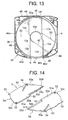
- FIG. 13 is a plan view showing a state where the aperture portion of the inner shell incorporated into the lower shell in FIG. 2 is deviated from the aperture portion of the lower shell.
- FIG. 20 is a perspective view of the inner shell in FIG. 4.
- the inner shell 4 is so formed as to be capable of accommodating the optical disc.
- the inner shell 4 includes a flat portion 40 made of a disc-like thin plate material and a ring portion 41 formed in continuation from an outer peripheral edge of the flat portion 40.
- the flat portion 40 of the inner shell 4 is formed with an aperture portion 42 of which a shape and a size are substantially the same as those of the aperture portion 6 of the lower shell 22.
- the ring portion 41 is formed in a cylindrical shape having a slightly larger diameter than an outside diameter of the ring-shaped rib 15 of the upper shell 21.
- the ring portion 41 protrudes (upward) along the outer periphery to form a space which the optical disc 3 resides in.
- the ring portion 41 is rotatably fitted in the outer peripheral portion of the ring-shaped rib 15, wherein the front end portion of the ring portion 41 is inserted into a ring-shaped recessed portion 17 provided outwardly of the ring-shaped rib 15.
- the inner shell 4 is made of a material having heat resistance and a small degree of deformation, and can be manufactured by molding from a heat-resistant plastic material such as polycarbonate and so on.
- a deflection temperature under load of such a material is equal to or higher than 135°C as a value at 1.80 MPa based on a load-deflection temperature testing method according to ISO75.
- the outer peripheral face of the ring portion 41 of the inner shell 4 is provided with a gear portion 43 having a multiplicity of teeth extending over a predetermined range in the peripheral direction.
- the gear portion 43 is provided to have an angular range that is slightly larger than an angle of rotation of the inner shell 4.
- the aperture portion 42 of the inner shell 4 is rotated most for the aperture portion 6 of the lower shell 22, and, when the pair of shutter portions 5a, 5b come to a closed state, one end of the gear portion 43 in the peripheral direction gets exposed from the aperture window 30. Further, as illustrated in FIG. 12, the inner shell 4 is rotated through a predetermined angle, and the aperture portion becomes aligned with the aperture portion 6. In this state, when the pair of shutter portions 5a, 5b are completely opened, the other end of the gear portion 43 in the peripheral direction is exposed from the aperture window 30.
- Stopper portions 44a, 44b for restricting an amount of rotational movement of the inner shell 4 are so provided on both sides of the gear portion 43 of the inner shell 4 as to protrude outside in the radial direction.
- the gear portion 43 and the stopper portions 44a, 44b are thus protruded outside from the outer peripheral face of the ring portion 41, and hence portions, corresponding to these protruded portions, of the upper shell 21 and of the lower shell 22 are respectively formed with escape grooves 45a, 45b for permitting the stopper portions 44a, 44b, etc. to pass through in a way that avoids contacts therewith.
- lift-up protruded portions 46 are provided in two positions in the peripheral direction on the front end face of the ring portion 41. These lift-up protruded portions 46 on the inner shell side, as shown in FIG. 13, run on the lift-up protruded portions 18 provided within the ring-shaped recessed portion 17 of the upper shell 21 in the state where the aperture portion 42 of the inner shell 4 is rotated most for the aperture portion 6 of the lower shell 22.
- a pair of support spindles 49, 49 for rotatably supporting the pair of shutter portions 5a, 5b in a plane direction are provided on the surface, on the opposite side to the ring portion 41, of the flat portion 40 of the inner shell 4.
- the pair of support spindles 49, 49 are provided one by one, showing point symmetry with respect to the aperture portion 42.
- trapezoidal protruded portions 48, 48 for release from the fitting are provided in the vicinities of the pair of support spindles 49, 49.
- These protruded portions 48, 48 for the release from the fitting serve to extract the rib-shaped protruded portion 12a out of the groove-shaped recessed portion 12b when moving to the position (the second position) in FIG. 12 where the shutter portions 5a, 5b unclose the aperture portion 6 from the position (the first position) in FIG. 13 where the shutter portions 5a, 5b close the aperture portion 6.
- the trapezoidal protruded portions 48, 48 for the release from the fitting are positioned sideways of the second and fourth closed portions 12e, 12g provided at the end portions of the rib-shaped protruded portion 12a taking substantially the H-shape that is provided on the lower shell 22 in the position shown in FIG. 13.
- the ring portion 41 formed along the outer periphery decreases in its rigidity due to a configuration thereof, and an aperture ring portion 41a, in which the ring portion 41 becomes thin at the aperture portion 42, has particularly a remarkable decrease in its rigidity.
- an available construction is that a ring-shaped member 41b having an outside diameter slightly larger than the outside diameter of the optical disc 3 and made of a linear metallic material is so attached as to be fitted into a root portion between the ring portion 41 and the flat portion 40 while getting elastically deformed. Owing to this construction, the ring-shaped member 41b elastically restores and is fitted into the root portion, whereby the rigidity of the ring portion 41 can be improved and the deformation is, even when an environmental change is caused, hard to occur.
- materials each having a load-deflection temperature (1.80 MPa) higher than 135°C be used as materials of the inner shell and of the ring-shaped member 41b of the inner shell in order to prevent the deformation caused by the temperature change.
- materials each having a percentage of water absorption is smaller than 0.2% (23°C, 24 hours) be employed for preventing the deformation of the cartridge due to a change in humidity.
- the materials of the ring-shaped member of the inner shell involve using plastic materials such as polyamide-imide, polyallylate, polycarbonate, polyether ether ketone, polyetherimide, polyether sulfone, polyimide, polyphenylene ether, polysulfone and so forth.
- plastic materials such as polyamide-imide, polyallylate, polycarbonate, polyether ether ketone, polyetherimide, polyether sulfone, polyimide, polyphenylene ether, polysulfone and so forth.
- plastic materials other than these materials can be used by their being filled with 10% through 30% of the filler such as the glass, etc.
- the metallic materials such as especially aluminum and an aluminum alloy.
- FIG. 14 is a perspective view of the shutter in FIG. 2 as viewed from the upper face.
- FIG. 15 is a perspective view of the shutter in FIG. 4 as viewed from the lower face.
- FIG. 16 is a perspective view showing a state where the shutter members in FIGS. 14 and 15 are attached to the inner shell in FIG. 4, and the aperture portions are opened.
- FIG. 17 is a perspective view showing a state where the shutter members in FIGS. 14 and 15 are attached to the inner shell in FIG. 4, and the aperture portions are closed.
- the shutter unit 5 is constructed of the pair of shutter portions 5a, 5b formed in substantially the same shape and size.
- the pair of shutter portions 5a, 5b are each composed of a plate member of which a plate thickness is substantially the same as the height of each of the first through fourth closed portions 12d - 12g of the rib-shaped protruded portion 12a, taking substantially a semi-circular shape, of the lower shell 22 in FIG. 9.
- Stepped portions 50 each formed to a predetermined length in a direction orthogonal to a line of chord, are provided at substantially a central portion of the chord side of each of the shutter portions 5a, 5b.
- a protruded joint portion 50a and a recessed joint portion 50b are formed through the stepped portions 50 on both sides. Further, the respective joint portions 50a, 50b are provided with protruded portions 51a, 51b protruding in an eave-like shape in a direction orthogonal to the chord extending direction.
- an end face of the protruded joint portion 50a and an end face of the recessed joint portion 50b thereof face each other, and the protruded portion 51a of the protruded joint portion 50a is superimposed on a protruded portion 51b of the recessed joint portion 50b.
- Bearing holes 52 are formed in spindle receiving portions 50c at the end portions of the recessed joint portions on the chord sides of the shutter portions 5a, 5b.
- Notched portions 50d for introducing the second closed portion 12e or the fourth closed portion 12g provided at the end portion of the rib-shaped protruded portion 12a, taking substantially the H-shape, of the lower shell 22, are provided at the end portions of the recessed joint portions 50b on the chord sides of the shutter portions 5a, 5b.
- the respective shutter portions 5a, 5b are rotatably attached to the inner shell 4 by fitting the support spindles, 49, 49 shown in FIG. 16 into the bearing holes 52.
- the pair of shutter portions 5a, 5b are attached in such a way that the chord sides thereof face each other.
- the pair of shutter portions 5a, 5b are, when rotated to separate away from each other toward the outside, so placed as to be superimposed on the side portions thereof on both sides, with the aperture portion 42 of the inner shell 4 being interposed therebetween.
- the joint portions 50a, 50b of the pair of shutter portions 5a, 5b are abutted on each other by rotating these shutter portions 5a, 5b inwardly, whereby the central portion of the aperture portion 42 is, as illustrated in FIG. 17, closed by the pair of shutter portions 5a, 5b.
- elongate holes (opening/closing grooves) 53 for opening and closing the shutter portions 5a, 5b are formed in the recessed joint portions 50b of the shutter portions 5a, 5b.
- the respective elongate holes 53 are formed extending in radial directions about the bearing holes 52 of the shutter portions 5a, 5b formed with these elongate holes 53.
- a boss-shaped protruded portion 20 of the lower shell 22 is slidably engaged with the elongate hole 53.
- outward end portions of the respective elongate holes 53 are provided with elastic pieces 54 formed by notching along the periphery and with recessed portions 53a for letting the boss-shaped protruded portions 20 escape.
- protruded pieces 55 for closing are provided at the ends of the circular arcs of the shutter portions 5a, 5b.
- the protruded piece 55 of the shutter portion 5a abuts on the first closed portion 12d of the lower shell 22, while the protruded piece 55 of the shutter portion 5b abuts on the third closed portion 12f of the lower shell 22, thereby closing a gap therebetween.
- the groove-shaped recessed portions 12b configuring the second dust infiltration blocking portion 12 by engaging with the rib-shaped protruded portions 12a taking substantially H-shape are formed in the slide faces of the shutter portions 5a, 5b with respect to the lower shell 22.
- the rib-shaped protruded portions 12a of the lower shell 22 are fitted in the grooved-shaped recessed portions 12b.
- the third dust infiltration blocking portion 13 structured of the multiplicity of rugged portions is provided inwardly of the second dust infiltration blocking portion 12.
- the shutter portions 5a, 5b involve using, as materials, synthetic resins such as an ABS resin (acrylonitrile butadiene styrene resin), HIPS (high impact polystyrene), POM (polyacetal) and so forth, and further preferable materials are of a type given slidability.
- synthetic resins such as an ABS resin (acrylonitrile butadiene styrene resin), HIPS (high impact polystyrene), POM (polyacetal) and so forth, and further preferable materials are of a type given slidability.
- other synthetic resins are applicable, and metallic materials such as an aluminum alloy, a stainless steel, etc. may also be employed.
- FIG. 18 is a plan view showing a state where the shutter in FIG. 17 completely closes the aperture portion.
- FIG. 19 is a plan view showing a state where the shutter in FIG. 16 completely uncloses the aperture portion.
- the pair of shutter portions 5a, 5b of the shutter unit 5 are maintained by their self-weights and a frictional force, etc. caused between the lower shell 22 and the inner shell 4 in such a state that the aperture portion 6 of the lower shell 22 and the aperture portion 42 of the inner shell 4 are completely closed. Further, there occurs a state wherein two pieces of lift-up protruded portions 46 of the inner shell 4 run on two pieces of lift-up protruded portions 18 provided in the ring-shaped recessed portions 17 of the upper shell 21. Therefore, the pair of shutter portions 5a, 5b are in a state of their being pinched from both sides by the upper shell 21 and the inner shell 4.
- a rack bar 70 of a shutter opening/closing mechanism of the recording/reproducing apparatus enters the guide groove 31 formed in the side face portion of the disc cartridge 1, whereby the operating portion 37 of the lock member 32 protruding into the guide groove 31 is intruded into the lock member accommodating portion 33 by a pressing force of the rack bar 70 while resisting a biasing force of the spring piece 38.
- a front end of a gear portion 70a meshes with the gear portion 43 of the inner shell 4, and the inner shell 4 rotates corresponding to an amount of movement of the rack bar 70.
- the rack bar 70 enters the guide groove 31m, corresponding to the loading of the disc cartridge 1, and, when the gear portion 70a thereof starts meshing with the gear portion 43 of the inner shell 4, the inner shell 4 is rotated counterclockwise.
- the lift-up protruded portions 46 of the inner shell 4 run on the lift-up protruded portions 18 of the upper shell 21, and the pair of shutter portions 5a, 5b are pinched between the inner shell 4 and the upper shell 21.
- the rotating operation of the inner shell 4 requires comparatively a large force.
- the inner shell 4 is rotated resisting a large frictional force caused when the lift-up protruded portions 18, 46 run on each other, whereby the lift-up protruded portions 46 disengage from the lift-up protruded portions 18 with the result that the frictional force vanishes. Consequently, thereafter the inner shell 4 can be rotated extremely lightly and smoothly.
- the trapezoidal protruded portions 48, 48 for the release from the fitting which are provided on the bottom face of the inner shell 4, run on the first and third closed portions 12d, 12f of the rib-shaped protruded portion 12a of the lower shell 22, and the inner shell 4 comes to a state of being lifted from the lower shell 22.
- the shutter portions 5a, 5b are likewise raised, and there occurs a state in which the grooved-shaped recessed portion 12b exit the rib-shaped protruded portion 12a.
- the respective bearing holes 52 of the shutter portions 5a, 5b are similarly rotated by the rotation of the inner shell 4, and on the other hand the boss-shaped protruded portions 20, 20 of the lower shell 22 are slidably engaged with the elongate holes 53 formed in the other end portion.
- the pair of boss-shaped protruded portions 20, 20 are provided on the lower shell 22 but do not move.
- the elongate holes 53 extend in a direction S that connects the bearing hole 52 to the boss-shaped protruded portion 20 so as to enable relative movements of the boss-shaped protruded portions 20, 20 in a way that follows up with the rotations of the shutter portions 5a, 5b.
- the boss-shaped protruded portions 20 relatively move toward the bearing holes 52 along within the elongate holes 53 in accordance with the amounts of rotations of the shutter portions 5a, 5b.
- the bearing holes 52 are thereby moved toward the corresponding boss-shaped protruded portions 20.
- the shutter portions 5a, 5b move, as shown in FIG. 19, to the portions on both sides of the aperture portion 42 of the inner shell 4, whereby the upper and lower aperture portions 6, 42 are completely opened. Consequently, part of the optical disc 3 housed in the optical disc accommodating portion gets exposed through the aperture portions 6, 42.
- the turntable 67 and the optical head (not shown) can be inserted into the aperture portions 6, 42 in the manner described above (see FIG. 10). Then, as illustrated in FIG. 11, with the relative movements of the turntable 67, etc. to the disc cartridge 1, the turntable 67 and the optical head enter the aperture portion 6, and the optical disc 3 within the disc cartridge 1 is placed on the table body portion 67a of the turntable 67. Then, the front end portion of the clamp shaft 67b advances into the circular recessed portion 7d of the clamp member 7, the clamp member 7 is magnetically attracted, and the optical disc 3 is pinched between the table body portion 67a and the clamp member 7 and is thus clamped. At this time, the collar portion 7c of the clamp member 7 is set in the non-contact state away from the bottom face portion 8b of the clamp presser member 8, and therefore the optical disc 3 and the clamp member 7 become rotatable.
- the optical disc 3 is rotated at a predetermined speed in a predetermined rotating direction by the turntable 67 of the recording/reproducing apparatus, and the optical head of the recording/reproducing apparatus records or reproduces the information signals on or from the optical disc 3 while facing the information recording area 29a on the optical disc 3.
- the disc cartridge 1 After recording or reproducing as described above, for example, the disc cartridge 1 is ejected out of the recording/reproducing apparatus by the aid of an operation of the loading mechanism of the recording/reproducing apparatus. At this time, as the disc cartridge 1 moves, the rack bar 70 in FIG. 19 relatively recedes. Along with the recession of the rack bar 70, the inner shell 4 and the pair of shutter portions 5a, 5b perform operations reversed to those when inserted as described above, thereby completely closing the aperture portions 6, 42 on the whole as in FIG. 18.
- the inner shell 4 closest to the optical disc 3 gets deformed on the occasion of an occurrence of an abrupt environmental change, a contact between the inner shell 4 and the optical disc 3 comes into a problem.
- the inner shell 4 is made of the material having the heat resistance and the small degree of deformation, and hence the rigidity of the inner shell 4 is improved. Even if the environmental change and temperature fluctuations are caused, it is possible to restrain the deformation of the inner shell 4 and to prevent the contact between the inner shell 4 and the optical disc 3 housed in the inner shell 4.
- the characteristic required of the inner shell 4 is that the inner shell 4 does not deform when the environment changed such as the change in temperature, etc. occurs, and the deflection temperature under load is given as a physical property remarkably reflected in the deformation caused when the temperature changes.
- the deflection temperature under load is a value obtained by the measurement based on the load-deflection temperature testing method specified by ISO75, and is defined as a temperature when a deflection amount reaches a certain specified value as the temperature under a fixed load (1.80 MPa) is gradually raised. Namely, the load-deflection temperature is, it may be said, reflected in how much the disc cartridge 1 accommodating the inner shell 4 warps depending on a stress applied when sharply changing the temperature.
- the rigidity of the disc cartridge 1 at the rising time of the temperature is also reflected, and hence it implies that if the value of this load-deflection temperature is large, the rigidity at the high-temperature time is large, while the warp is small. Accordingly, the temperature is approximately 70°C at the maximum under a normally-considered usage environment at the high temperature, so that a desirable load-deflection temperature of the inner shell 4 is higher than 70°C, and a more desirable temperature is equal to or higher than, e.g., 135°C.
- the load-deflection temperature of the inner shell 4 is set equal to or higher than 135°C, the inner shell 4 is hard to deform in the case of the occurrence of the environmental change such as the change in temperature, etc., and therefore the contact between the inner shell 4 and the optical disc can be avoided.
- the measurement of the warp involves using a high-precision angle measuring device (LA-2000 made by Keyence Corporation).
- LA-2000 made by Keyence Corporation
- the measurement under the environment in which the temperature abruptly changes is conducted, wherein a door-attached case (CGO-1, 30 X 40 X 60 cm, made by Aswan Corporation) having a built-in temperature adjusting means is set in a state of being retained at 70°C, then the inner shell single body and the disc cartridge accommodating the inner shell and the optical disc, which have been stabilized at 25°C, are taken out and encased in the door-attached case retained at 70°C, and amounts of changes in their warps were measured. It is of importance to measure the change in a short period of time, and hence a series of processes of taking out the objects under the measurement through starting the measurement were executed quickly.
- the load-deflection temperature testing method pursuant to the ISO75 was performed, wherein there was measured a deflection amount as the temperature was increased under the fixed load of 1.80 MPa, and there was obtained a temperature at the time when this deflection amount has reached a predetermined value.
- the similar measurement was conducted by way of a comparative example, wherein the materials shown in the following Table 1 were used.
- the best mode for carrying out the present invention has been discussed so far, however, the present invention is not limited to the best mode and the examples given above and can be modified in a variety of forms within the scope of the technical concept of the present invention. For instance, as shown in FIG.
- the configuration of the inner shell may take such a structure that the aperture portion 42a is formed as large as about the diameter in the diametrical direction.
- the aperture portion 42a is thus large in the diametrical direction, a remarkable decrease in its strength is seen, however, the deformation caused when the temperature fluctuates can be restrained by applying the present invention.
- the optical disc accommodable in the disc cartridges in FIGS. 1 to 21 may be a reproduction-only (read-only) optical disc previously recorded with the information signals, a recordable (write-once) optical disc on which the information signals can be recorded once, or an (erasable) optical disc on which the information signals can be repeatedly recorded.
- a preferable optical disc is an optical disc capable of high-density recording/reproducing by use of blue-violet laser beams having a wavelength that is on the order of 405 nm.
Landscapes
- Optical Record Carriers And Manufacture Thereof (AREA)
- Feeding And Guiding Record Carriers (AREA)
Abstract
Disclosed is a disc cartridge capable of
preventing a contact between an optical disc and the
cartridge even when an environmental change occurs in
a structure that an inner shell is provided in an
interior of a shell unit. This disc cartridge
includes a shell unit for accommodating an optical
disc rotatably and in a shielded state, and an inner
shell disposed in an interior of the shell unit and
including a ring portion so protruded to an outer
periphery as to form a space where the optical disc
exists, wherein the inner shell is made of a metallic
material or of a heat resistant plastic material of
which a deflection temperature under load is equal to
or higher than 135°C so that the inner shell exhibits
heat resistance and its deformation becomes small.
Description
- The present invention relates to a disc cartridge in which an interior of a shell unit accommodates a disc-shaped recording medium and an inner shell.
- A Blu-ray disc classified as an optical disc having a higher recording density than that of a DVD has recently been utilized by way of an optical recording medium. In this Blu-ray disc, however, a spot diameter (spot size) of a laser beam is by far smaller, and consequently dusts, flaws, etc. are easy to affect recording and reproducing. Therefore, a cartridge for the Blu-ray disc as disclosed in Japanese Patent Application Laid-Open Publication No.2003-109352 tries to increase a sealing degree by providing an inner shell in addition to a normal shell unit of the cartridge in order to prevent ambient dusts from entering the cartridge. As the sealing degree of the cartridge is increased, the cartridge, if it deforms, becomes easy to abut on the disc. Hence, in case an abrupt environmental change occurs, a plastic material normally used for forming the cartridge member warps, with the result that the cartridge is brought into contact with the disc.
- It is an object of the present invention to provide a disc cartridge capable of preventing a contact between a disc-shaped recording medium and a cartridge even when an environmental change occurs in a structure that an inner shell is provided in an interior of a shell unit.
- A disc cartridge according to the present embodiment includes a shell unit for accommodating a disc-shaped recording medium rotatably and in a shielded state, and an inner shell disposed in an interior of the shell unit and including a ring portion so protruded to an outer periphery as to form a space where the disc-shaped recording medium exists, wherein the inner shell is made of a metallic material or of a heat resistant plastic material of which a deflection temperature under load is equal to or higher than 135°C, preferably 150°C so that the inner shell exhibits heat resistance and its deformation becomes small.
- According to this disc cartridge, the inner shell forming the space where the disc-shaped recording medium exists is made of the material exhibiting the heat resistance and the small degree of deformation. It is therefore feasible to restrain the deformation of the inner shell even when the environmental change occurs and to prevent the contact between the disc-shaped recording medium and the cartridge.
- Note that polyamide-imide, polyallylate, polycarbonate, polyether ether ketone, polyetherimide, polyether sulfone, polyimide, polyphenylene ether and polysulfone, are preferable to materials of the inner shell. Especially, each of polycarbonate, polyether ether ketone and polyphenylene ether has a low percentage of water absorption equal to or smaller than 0.2%, and has a merit against a change in humidity. Moreover, including the above materials, even plastic materials other than these materials can be used by their being filled with 10% through 30% of filler such as glass, etc.. Further, light-weight metallic materials such as aluminum and an aluminum alloy are preferable as the metallic materials.
- Herein, [the deflection temperature under load] in this specification is a value at 1.80 MPa based on a load-deflection temperature testing method according to ISO75. The warp of the cartridge itself along with an abrupt change in temperature is thus measured, and the deflection temperature under load is obtained, whereby a material proper to the inner shell can be selected.
- Further, a ring-shaped member having an outside diameter slightly larger than an outer periphery of the disc-shaped recording medium, is fitted in the vicinity of a root portion of the ring portion of the inner shell, thereby enabling effective restraint of the deformation of the inner shell.
- As described above, the contact between the cartridge and the disc-shaped recording medium can be prevented by causing none of the deformation of the inner shell. Particularly, it is possible to prevent the contact therebetween by retaining the cartridge while causing no change in the configuration of the ring portion of the inner shell even when the abrupt environmental change occurs.
- It is preferable to prevention of the deformation of the inner shell due to the environmental change that materials each having a load-deflection temperature (1.80 MPa) higher than 135°C be used as materials of the inner shell and of the ring-shaped member of the inner shell in order to prevent the deformation caused by the temperature change. Further, it is similarly preferable that materials each having a percentage of water absorption is smaller than 0.2% (23°C, 24 hours) be employed for preventing the deformation of the cartridge due to a change in humidity. With this contrivance, even when exposed to a high-temperature/high-humidity severe environment, the cartridge does not deform and can be prevented from abutting on the disc-shaped recording medium. Further, even a material that does not satisfy these conditions can gain a high load-deflection temperature and a small percentage of water absorption by its being filled with 10% through 30% of filler such as glass and so on.
- Moreover, the disc cartridge can take such a configuration that the shell unit has a first aperture, and the inner shell has a second aperture taking substantially the same shape as the first aperture, the disc cartridge further includes a shutter disposed between the shell unit and the inner shell, and the first aperture is opened and closed by rotating the inner shell relatively to the shutter and the shell unit.
- According to the disc cartridge in the present embodiment, it is feasible to prevent the contact between the disc-shaped recording medium and the cartridge even when the environmental change occurs in the structure that the interior of the shell unit is provided with the inner shell.
-
- FIG. 1 is a perspective view showing a disc cartridge as viewed from the side of an upper shell in a best mode for carrying out the present invention;
- FIG. 2 is an exploded perspective view of the disc cartridge in FIG. 1;
- FIG. 3 is a perspective view showing the disc cartridge in FIG. 1 in a shutter-closed state as viewed from the side of a lower shell;
- FIG. 4 is an exploded perspective view of the disc cartridge in FIG. 3;
- FIG. 5 is a view showing an inner surface of the upper shell in FIG. 4;
- FIG. 6 is a view showing an inner surface of the lower shell in FIG. 2;
- FIG. 7 is a perspective view showing the upper shell in FIG. 4, a clamp member and a clamp presser member;
- FIG. 8 is a sectional view of the disc cartridge as viewed by cutting it in a direction along the line VIII-VIII in FIG. 1;
- FIG. 9 is a sectional view of the disc cartridge as viewed by cutting it in a direction along the line IX-IX in FIG. 3;
- FIG. 10 is a principal sectional view showing a pre-clamped state of the clamp member of the cartridge in FIGS. 1 and 3 which is loaded into the recording/reproducing apparatus;
- FIG. 11 is a principal sectional view showing a state where the clamp member of the cartridge in FIGS. 1 and 3 which is loaded into the recording/reproducing apparatus is clamped down to a clamp shaft on the side of the apparatus;
- FIG. 12 is a plan view showing a state where an aperture portion of an inner shell incorporated into the lower shell in FIG. 2 is aligned with an aperture portion of the lower shell;
- FIG. 13 is a plan view showing a state where the aperture portion of the inner shell incorporated into the lower shell in FIG. 2 is deviated from the aperture portion of the lower shell;
- FIG. 14 is a perspective view of the shutter in FIG. 2 as viewed from the upper face;
- FIG. 15 is a perspective view of the shutter in FIG. 4 as viewed from the lower face;
- FIG. 16 is a perspective view showing a state where shutter members in FIGS. 14 and 15 are attached to the inner shell in FIG. 4, and the aperture portions are opened;
- FIG. 17 is a perspective view showing a state where the shutter members in FIGS. 14 and 15 are attached to the inner shell in FIG. 4, and the aperture portions are closed;
- FIG. 18 is a plan view showing a state where the shutter member in FIG. 17 completely closes the aperture portion; FIG. 19 is a plan view showing a state where the shutter member in FIG. 16 completely uncloses the aperture portion;
- FIG. 20 is a perspective view of the inner shell; and
- FIG. 21 is a perspective view showing a modified example of the inner shell in FIG. 20.
-
- A disc cartridge in a best mode for carrying out the present invention will hereinafter be described with reference to the drawings.
- FIG. 1 is a perspective view showing the disc cartridge as viewed from the side of an upper shell. FIG. 2 is an exploded perspective view of FIG. 1. FIG. 3 is a perspective view showing the disc cartridge in a shutter-closed state as viewed from the side of a lower shell. FIG. 4 is an exploded perspective view of FIG. 3. FIG. 5 is a view showing an inner surface of the upper shell in FIG. 4. FIG. 6 is a view showing an inner surface of the lower shell in FIG. 2. FIG. 7 is a perspective view showing the upper shell, a clamp member and a clamp presser member. FIG. 8 is a sectional view of the disc cartridge as viewed by cutting it in a direction along the line VIII-VIII in FIG. 1. FIG. 9 is a sectional view of the disc cartridge as viewed by cutting it in a direction along the line IX-IX in FIG. 3.
- As shown in FIGS. 1 to 7, a
disc cartridge 1 includes acartridge box body 2, aninner shell 4 and ashutter unit 5. Thecartridge box body 2 accommodates anoptical disc 3 in a rotatable manner, and has anupper shell 2 and alower shell 22 formed with afirst aperture portion 6 for recording and reproducing. Thecartridge box body 2 is constructed by superimposing aperipheral wall 21a of theupper shell 21 on aperipheral wall 22a of thelower shell 22, and accommodates theoptical disc 3, theinner shell 4 and theshutter unit 5. Theinner shell 4 has asecond aperture portion 42 taking substantially the same shape as thefirst aperture portion 6, and theshutter unit 5 is connected to theinner shell 4 and opens and closes thefirst aperture portion 6. - In the
cartridge box body 2, when rotating theinner shell 4 in one direction, theshutter unit 5 moves to a first position in which to close thefirst aperture portion 6 formed in thecartridge box body 2. When rotating theinner shell 4 in a reversed direction, theshutter unit 5 moves to a second position in which to open thefirst aperture portion 6 formed in thecartridge box body 2. - A
clamp member 7 is so secured by theclamp presser member 8 to the inner surface of theupper shell 21 as to be movable in vertical directions. When thedisc cartridge 1 is loaded into a recording/reproducing apparatus, theclamp member 7 is magnetically attracted toward a turntable of the recording/reproducing apparatus. Theclamp member 7 pinches theoptical disc 3 between the turntable of the recording/reproducing apparatus and theclamp member 7 itself, and then clamps theoptical disc 3 down. - As shown in FIGS. 1, 3, 4, 5 and 7, the
upper shell 21 is structured of a member taking a rectangular shape with a front sided portion formed in a circular arc or substantially a square shape. An outer peripheral edge portion of theupper shell 21 is provided with theperipheral wall 21a, and a first recessedportion 21p for fitting theclamp member 7 is formed in a central portion of the inner surface of theupper shell 21. The first recessedportion 21p includes first and second alignment (positioning) pins 21q, 21r inserted into first and second alignmentpin insertion holes portion 8d of theclamp presser member 8. The first and second alignment pins 21q, 21r are formed by resin molding integrally with theupper shell 21, corresponding to the first and second alignmentpin insertion holes clamp presser member 8. - Further, a second recessed
portion 21s, into which acollar portion 7c of theclamp member 7 is inserted, is formed along an inner periphery of the first recessedportion 21p in the inner surface of theupper shell 21. A clamp membermovement regulating portion 9, taking substantially a cone trapezoidal shape, for regulating a movement amount of theclamp member 7, is protruded at a central portion of the second recessedportion 21s. A central portion of the clamp membermovement regulating portion 9 is formed with a recessedportion 9a into which an upper face side of the recessedportion 7d of theclamp member 7 is inserted. Further, theperipheral wall 21a of theupper shell 21 has afront edge portion 21b, a pair ofside edge portions rear edge portion 21e. A central portion of therear edge portion 21e is formed with an alignment recessedportion 21f for alignment with thelower shell 22. - Provided, as shown in FIGS. 5 and 8, inwardly of the
peripheral wall 21a are first dust-proof walls 11a at a corner portion between the frontside edge portion 21b and oneside edge portion 21c, at a corner portion between oneside edge portion 21c and the rearside edge portion 21e, and at a corner portion between the rearside edge portion 21e and the otherside edge portion 21d. Spaces where second dust-proof walls 11b of thelower shell 22 in FIG. 8 are positioned, are formed between the first dust-proof walls 11a and theperipheral wall 21a. - As shown in FIGS. 5 and 7, at the respective corner portions along the inner surface of the
upper shell 21, circular-arc ribs 14 having substantially the same height of those of the first dust-proof walls 11a are each formed in a circular-arc shape extending from one side end of the first dust-proof wall 11a to the other side end thereof inwardly of the first dust-proof walls 11a. A ring-shapedrib 15 is provided inwardly of the circular-arc ribs 14. An internal area defined by the ring-shapedrib 15 within theinner shell 4 configures an accommodating portion for accommodating theoptical disc 3. - A ring-shaped recessed
portion 17, into which a front side end of the ring portion of theinner shell 4 is fitted, is provided outwardly of the ring-shapedrib 15. Lift-up protrudedportions 18 for moving theinner shell 4 in such a direction as to separate away from thelower shell 22, are provided in front-and-rear symmetric positions (which are phase-shifted 180 degrees) on a bottom face of the ring-shaped recessedportion 17. The protrudedportions 18 move theinner shell 4 in such a direction as to separate away from theupper shell 21 as inner-shell-sided protrudedportions 46 provided on a front side end face of thering portion 41 of the inner shell run thereon. - As shown in FIGS. 1, 2, 3 and 6, the
lower shell 22 is, as in the case of theupper shell 21, structured of a member taking a rectangular shape with a front sided portion formed in a circular arc or substantially a square shape. An outer peripheral edge portion of thelower shell 22 is provided with aperipheral wall 22a. Theperipheral wall 22a is constructed of afront edge portion 22b, a pair ofside edge portions rear edge portion 22e. A central portion of therear edge portion 22e is provided with an alignment protrudedportion 22f for alignment with theupper shell 21. - Provided, as shown in FIG. 6, inwardly of the
peripheral wall 22a of thelower shell 22 are second dust-proof walls 11b at a corner portion between the frontside edge portion 22b and oneside edge portion 22c, at a corner portion between oneside edge portion 22c and the rearside edge portion 22e, and at a corner portion between the rearside edge portion 22e and the otherside edge portion 22d. The second dust-proof wall 11b is, as shown in FIG. 8, thinner than theperipheral wall 22a of thelower shell 22 and is so formed integrally with theperipheral wall 22 as to protrude from a front side end of theperipheral wall 22a. - As shown in FIG. 6, circular-
arc ribs 19 having substantially the same height of those of the first dust-proof walls 11a are each formed in a circular-arc shape extending from one side end of the second dust-proof wall 11b to the other side end thereof inwardly of the second dust-proof walls 11b. An internal area defined by the ring-shapedribs 19 of thelower shell 22 configures an accommodating portion for accommodating substantially a half of theinner shell 4 in wall-thicknesswise direction and the pair ofshutter unit 5. - The
upper shell 21 is superimposed on thelower shell 22 so that theperipheral walls portion 22f is fitted in the alignment recessedportion 21f. Owing to the superimposition of the upper andlower shells proof wall 11b protruding from theperipheral wall 22a of thelower shell 22 enters between the first dust-proof wall 11a of theupper shell 21 and theperipheral wall 21a. Thus, the first dust-proof wall 11a of theupper shell 21 cooperates with the second dust-proof wall 11b and theperipheral wall 22a of thelower shell 22 to build up a first dustinfiltration blocking portion 11. - In the first dust
infiltration blocking portion 11, the first dust-proof wall 11a of theupper shell 21 takes substantially a double-wall structure, and the second dust-proof wall 11b of thelower shell 22 is inserted along the first dust-proof wall 11a in a way that superimposes these walls on each other with predetermined clearances C. - Note that the circular-
arc rib 14 of theupper shell 21 is superimposed on the circular-arc rib 19 of thelower shell 22 inwardly (on the side of the optical disc accommodating portion) of the first dustinfiltration blocking portion 11, wherein a dust infiltration blocking portion is also configured in this area. - As shown in FIGS. 6 and 9, a slide surface (contact surface) between the
lower shell 22 and theshutter unit 5 is provided with a second crank-shaped dustinfiltration blocking portion 12 for blocking the dusts infiltrating into an area on the side of theoptical disc 3 from theaperture portion 6 in the first position where theshutter unit 5 closes theaperture portion 6 of thelower shell 22. - The second dust
infiltration blocking portion 12 is constructed of a rib-shaped protrudedportion 12a provided on thelower shell 22 so as to surround theaperture portion 6, and a groove-shaped recessedportion 12b formed in theshutter unit 5 so that the rib-shaped protrudedportion 12a is fitted in this recessedportion 12b when moving to the first position where theshutter unit 5 closes theaperture portion 6. -
Inclined faces 12c are formed with side end portions of the rib-shaped protrudedportion 12a and of the groove-shaped recessedportion 12b in a widthwise direction, whereby the rib-shaped protrudedportion 12a gets easy to exit the groove-shaped recessedportion 12b when theshutter unit 5 moves to the second position in which to open theaperture portion 6 from the first position in which to close theaperture portion 6. Further, a third rugged dustinfiltration blocking portion 13 is provided on a more inside face than the second dustinfiltration blocking portion 12 on the slide surface of theshutter unit 5. - As shown in FIG. 6, the
aperture portion 6 formed extending from the central portion of thelower shell 22 to thefront edge portion 22b, serves to make the turntable of an optical disc rotary drive mechanism on the side of the recording/reproducing apparatus and an optical head of an optical pickup device approach theoptical disc 3. A breadth of theaperture portion 6 is set large enough to permit the turntable and the optical head to come in and out without any restrictions. - The rib-shaped protruded
portion 12a configuring the second dustinfiltration blocking portion 12 in FIG. 9, is formed in substantially an H-like shape in plane so as to surround theaperture portion 6 and with a height of approximately 0.5 mm. Four pieces of side end portions of the rib-shaped protrudedportion 12a taking substantially the H-like shape are provided with first through fourthclosed portions 12d through 12g. Each of the first through fourthclosed portions 12d through 12g is formed with a height that is approximately four times the height of the rib-shaped protrudedportion 12a. - The four side end portions of the rib-shaped protruded
portion 12a taking substantially the H-like shape are connected to the circular-arc ribs 19 via the first through fourthclosed portions 12d through 12g. Further, boss-shaped protrudedportions 20 to be inserted intoelongate holes 53 of the pair ofshutter portions lower shell 22. - The boss-shaped protruded
portions 20 are formed one by one on both sides, wherein the rib-shaped protrudedportion 12a taking substantially the H-like shape is interposed therebetween. - Moreover, as shown in FIG. 3, an
aperture window 30 for exposing part of agear portion 43 provided on the outer peripheral surface of theinner shell 4, is provided at substantially a central portion between oneside edge portions upper shell 21 and of thelower shell 22. Thisaperture window 30 is structured of an upper shell sidedbotch portion 30a formed in theupper shell 21 and a lower shell sidednotch portion 30b formed in thelower shell 22. - Further, the one
side edge portions upper shell 21 and of thelower shell 22 are formed withguide grooves 31 extending in front-and-rear directions along a joint face between these oneside edge portions guide grooves 31 are formed for preventing mis-insertion, etc. when loading thedisc cartridge 1 into the recording/reproducing apparatus. Theaperture window 30 communicates with theguide grooves 31. - As shown in FIGS. 2 and 6, a lock
member accommodating portion 33 for rotatably accommodating alock member 32 is provided at a corner portion between the frontside edge portion 22b and the oneside edge portion 22d of thelower shell 22. The lockmember accommodating portion 33 communicates with the accommodating portion of the inner shell, etc. of the lower shell, and also communicates with theguide groove 31 via abore 34 formed in the oneside edge portion 22d. Further, the lockmember accommodating portion 33 of thelower shell 22 is provided with asupport spindle 35 for rotatably supporting thelock member 32 so that thesupport spindle 35 protrudes toward theupper shell 21. - The
lock member 32 is formed as a lever-like member rotatably fitted to thesupport spindle 35 and swingable in a plane-direction. One side end of thelock member 32 in a longitudinal direction is provided with a stopper portion having a plurality of teeth, while the other side end thereof in the longitudinal direction is provided with an operatingportion 37. Furthermore, thelock member 32 is provided integrally with aspring piece 38 protruding in the same direction as thestopper portion 36 does in a way that faces thestopper portion 36. - The
lock member 32 is constructed such that thestopper portion 36 is fitted to thesupport spindle 35 in a state of being directed to the accommodating portion of the inner shell, etc., and thespring piece 38 abuts on the inner face of thefront edge portion 22b. Thestopper portion 36 is biased toward the accommodating portion of the inner shell, etc. by a spring force of thespring piece 38, and the operatingportion 37 penetrates thebore 34 from the inside and protrudes into theguide groove 31. - Further, a mis-erasing
preventive member 92 for preventing mis-erasing of information recorded on the optical disc is fitted to a mis-erasing preventivemember fitting portion 91 provided at the corner portion between the oneside edge portion 22c and therear edge portion 22e of thelower shell 22. - As described above, in the
disc cartridge 1, the respective dust infiltration blocking portions eliminate the possibility of the infiltration of dusts, wherein the interior accommodating theoptical disc 3 is surely set in a shielded state. This configuration is therefore preferable to a case of accommodating the optical disc such as a Blu-ray disc on which high-density recording or reproducing is effected by use of small-diameter laser beam spots of blue-violet laser beams having a wavelength of approximately 405 nm. - The clamp member in FIGS. 2 and 4 will be explained with reference to FIGS. 7, 10 and 11. FIG. 10 is a principal sectional view showing a pre-clamped state of the clamp member of the cartridge loaded into the recording/reproducing apparatus. FIG. 11 is a principal sectional view showing a state where the clamp member of the cartridge loaded into the recording/reproducing apparatus is clamped down to a clamp shaft on the side of the apparatus.
- As shown in FIGS. 7 and 10, the
clamp member 7 is configured in a circular shape on the whole, and includes a circularbottom face portion 7a, a conicperipheral portion 7b provided on an outer peripheral portion of thebottom face portion 7a, and acollar portion 7c provided on the side of a large-diameter portion of the conicperipheral portion 7b. - A central portion of the circular
bottom face portion 7a is formed with a conic recessedportion 7d that receives, via acentral hole 3a of theoptical disc 3, insertion of the front end portion of aclamp shaft 67b of aturntable 67 on the side of the recording/reproducing apparatus. The peripheral edge portion of thebottom face portion 7a is provided with a ring-shapedprotruded portion 7e abutting on the surface of theoptical disc 3 and thus pressing theoptical disc 3 on the vicinity of thecentral hole 3a. - The
clamp member 7 is made of a plate material of a mild steel, a stainless steel and so on. Theclamp member 7 is formed integrally by press-working this type of plate material. Theclamp member 7 is made of a magnetic material and is therefore absorbed (attracted) to a front end portion, constructed of a permanent magnet, of theclamp shaft 67b. - As shown in FIGS. 7 and 10, the
clamp presser member 8 is configured in the circular shape having the central hole on the whole. Theclamp presser member 8 includes a larger-diameter hole 8a than theperipheral wall 7b of theclamp member 7 at its central portion, a ring-shapedbottom face portion 8b formed larger in its diameter than thecollar portion 7c of theclamp member 7, aperipheral wall portion 8c provided along a peripheral portion of thebottom face portion 8b, and a collar-shapedfixing portion 8d provided extending along from the front end side of theperipheral wall portion 8c up to the outer periphery. First and second alignmentpin insertion holes fixing portion 8d. The first alignmentpin insertion hole 8e is formed as a round hole, while the second alignmentpin insertion hole 8f is formed as an elongate hole. - Further, a width D1 of the
collar portion 7c of theclamp member 7 is set smaller than a width D2 of the ring-shapedbottom face portion 8b of theclamp presser member 8. Moreover, awelding rib 8g is provided on a fitting face of the collar-shapedfixing portion 8d to theupper shell 21. Theclamp presser member 8 is integrally formed of a synthetic resin, etc. by injection molding. - When attaching the
clamp presser member 8 to theupper shell 21, thecollar portion 7c of theclamp member 7 is placed within the first recessedportion 21p of theupper shell 21. Next, the fixingportion 8d of theclamp presser member 8 is placed within the second recessedportion 21s of theupper shell 21, and the first and second alignment pins 21q, 21r provided on the second recessedportion 21s are inserted into the first and secondpin insertion holes clamp presser member 8 is aligned (positioned), and the front end of thewelding rib 8g is melted by supersonic waves, whereby the clamp presser member is joined by welding to theupper shell 21. - As described above, the
clamp member 7 is so held by theclamp presser member 8 against the inner face of the upper sell as to be movable in the vertical directions in FIG. 10. Specifically, as shown in FIG. 10, theclamp member 7 is held such that thecollar portion 7c of theclamp member 7 is supported on the ring-shapedbottom face portion 8b of theclamp presser member 8, thebottom face portion 7a of theclamp member 7 droops from thehole 8a formed in the ring-shapedbottom face portion 8b of theclamp presser member 8, and, on this occasion, thebottom face portion 7a is automatically centered at the center of thehole 8a since theperipheral wall portion 7b of theclamp member 7 is formed in the conical shape. - The width D1 of the
collar portion 7c of theclamp member 7 is set smaller than the width D2 of the ring-shapedbottom face portion 8b of theclamp presser member 8, and hence the outer peripheral face of thecollar portion 7c of theclamp member 7 and the inner peripheral face of theperipheral wall portion 8c of theclamp presser member 8, are kept in a non-contact state. - The operation of the clamp member described above will be explained.
- When loading the
disc cartridge 1 into the recording/reproducing apparatus, a relative position between thedisc cartridge 1 and the turntable of the apparatus is given as shown in FIG. 10. - Next, as illustrated in FIG. 11, the
optical disc 3 within thedisc cartridge 1 is placed on atable body portion 67a of theturntable 67, and the front end portion of theclamp shaft 67b enters the circular recessedportion 7d of theclamp member 7. Then, theclamp member 7 is magnetically attracted to the front end portion of theclamp shaft 67b, and theoptical disc 3 is pinched between thetable body portion 67a and theclamp member 7 and is thus clamped. At the same time, thecollar portion 7c of theclamp member 7 is set in the non-contact state away from thebottom face portion 8b of theclamp presser member 8, and therefore theoptical disc 3 and theclamp member 7 become rotatable. Further, as shown in FIG. 11, the non-contact state is kept by ensuring sufficient gap dimensions for a clearance K1 in the vertical direction in FIG. 11 between a lower face of thecollar portion 7c of theclamp member 7 and the ring-shapedbottom face portion 8b of theclamp presser member 8 and for a clearance K2 between an upper face of thecollar portion 7c and the inner face of theupper shell 21. - In the manner described above, the
optical disc 3 is chucked by theclamp member 7 down to theturntable 67 of the recording/reproducing apparatus, and is rotated at a predetermined speed while being integral with the table 67 in a rotating direction. Then, as shown in FIG. 10, one surface of theoptical disc 3 is formed with aninformation recording area 29a capable of recording the information and with anon-recording area 29b incapable of recording the information. Then, the optical head of the recording/reproducing apparatus is positioned facing theinformation recording area 29a, wherein the information can be recorded on and reproduced from theoptical disc 3. - Subsequently, the inner shell for rotatably accommodating the optical disc within the
cartridge box body 2, will be explained with reference to FIGS. 2, 12, 13 and 20. FIG. 12 is a plan view showing a state where the aperture portion of the inner shell incorporated into the lower shell in FIG. 2 is aligned with the aperture portion of the lower shell. FIG. 13 is a plan view showing a state where the aperture portion of the inner shell incorporated into the lower shell in FIG. 2 is deviated from the aperture portion of the lower shell. FIG. 20 is a perspective view of the inner shell in FIG. 4. - As shown in FIGS. 2, 4 and 20, the
inner shell 4 is so formed as to be capable of accommodating the optical disc. Theinner shell 4 includes aflat portion 40 made of a disc-like thin plate material and aring portion 41 formed in continuation from an outer peripheral edge of theflat portion 40. Theflat portion 40 of theinner shell 4 is formed with anaperture portion 42 of which a shape and a size are substantially the same as those of theaperture portion 6 of thelower shell 22. - The
ring portion 41 is formed in a cylindrical shape having a slightly larger diameter than an outside diameter of the ring-shapedrib 15 of theupper shell 21. Thering portion 41 protrudes (upward) along the outer periphery to form a space which theoptical disc 3 resides in. Thering portion 41 is rotatably fitted in the outer peripheral portion of the ring-shapedrib 15, wherein the front end portion of thering portion 41 is inserted into a ring-shaped recessedportion 17 provided outwardly of the ring-shapedrib 15. - The
inner shell 4 is made of a material having heat resistance and a small degree of deformation, and can be manufactured by molding from a heat-resistant plastic material such as polycarbonate and so on. A deflection temperature under load of such a material is equal to or higher than 135°C as a value at 1.80 MPa based on a load-deflection temperature testing method according to ISO75. - As shown in FIGS. 2 and 12, the outer peripheral face of the
ring portion 41 of theinner shell 4 is provided with agear portion 43 having a multiplicity of teeth extending over a predetermined range in the peripheral direction. Thegear portion 43 is provided to have an angular range that is slightly larger than an angle of rotation of theinner shell 4. - As shown in FIG. 13, the
aperture portion 42 of theinner shell 4 is rotated most for theaperture portion 6 of thelower shell 22, and, when the pair ofshutter portions gear portion 43 in the peripheral direction gets exposed from theaperture window 30. Further, as illustrated in FIG. 12, theinner shell 4 is rotated through a predetermined angle, and the aperture portion becomes aligned with theaperture portion 6. In this state, when the pair ofshutter portions gear portion 43 in the peripheral direction is exposed from theaperture window 30. -
Stopper portions inner shell 4 are so provided on both sides of thegear portion 43 of theinner shell 4 as to protrude outside in the radial direction. Thegear portion 43 and thestopper portions ring portion 41, and hence portions, corresponding to these protruded portions, of theupper shell 21 and of thelower shell 22 are respectively formed withescape grooves stopper portions - As illustrated in FIG. 12, when the
aperture portion 42 of theinner shell 4 and the aperture portion of thelower shell 22 come to their aligned state, one end portion of thestopper portion 44a engages with astopper engaging portion 45c provided at one end portion of theescape groove 45a, thereby blocking a further rotation of theinner shell 4. Moreover, as shown in FIG. 13, when theaperture portion 42 of theinner shell 4 comes to a state of being inclined most to theaperture portion 6 of thelower shell 22, one end portion of thestopper portion 44b engages with astopper engaging portion 45d provided at one end portion of theaperture portion 6, thereby blocking a further rotation of theinner shell 4. - Moreover, lift-up protruded
portions 46 are provided in two positions in the peripheral direction on the front end face of thering portion 41. These lift-up protrudedportions 46 on the inner shell side, as shown in FIG. 13, run on the lift-up protrudedportions 18 provided within the ring-shaped recessedportion 17 of theupper shell 21 in the state where theaperture portion 42 of theinner shell 4 is rotated most for theaperture portion 6 of thelower shell 22. - Further, as shown in FIG. 12, a pair of
support spindles shutter portions ring portion 41, of theflat portion 40 of theinner shell 4. The pair ofsupport spindles aperture portion 42. - Moreover, trapezoidal protruded
portions portion 12a taking substantially the H-shape that is provided on thelower shell 22, are provided in the vicinities of the pair ofsupport spindles portions portion 12a out of the groove-shaped recessedportion 12b when moving to the position (the second position) in FIG. 12 where theshutter portions aperture portion 6 from the position (the first position) in FIG. 13 where theshutter portions aperture portion 6. The trapezoidal protrudedportions closed portions portion 12a taking substantially the H-shape that is provided on thelower shell 22 in the position shown in FIG. 13. - Further, as shown in FIG. 20, in the
inner shell 4, thering portion 41 formed along the outer periphery decreases in its rigidity due to a configuration thereof, and anaperture ring portion 41a, in which thering portion 41 becomes thin at theaperture portion 42, has particularly a remarkable decrease in its rigidity. Such being the case, as depicted by a broken line in FIG. 2, an available construction is that a ring-shaped member 41b having an outside diameter slightly larger than the outside diameter of theoptical disc 3 and made of a linear metallic material is so attached as to be fitted into a root portion between thering portion 41 and theflat portion 40 while getting elastically deformed. Owing to this construction, the ring-shaped member 41b elastically restores and is fitted into the root portion, whereby the rigidity of thering portion 41 can be improved and the deformation is, even when an environmental change is caused, hard to occur. - As described above, it is preferable to prevention of the deformation of the inner shell due to the environmental change that materials each having a load-deflection temperature (1.80 MPa) higher than 135°C be used as materials of the inner shell and of the ring-shaped member 41b of the inner shell in order to prevent the deformation caused by the temperature change. Further, it is similarly preferable that materials each having a percentage of water absorption is smaller than 0.2% (23°C, 24 hours) be employed for preventing the deformation of the cartridge due to a change in humidity. With this contrivance, even when exposed to a high-temperature/high-humidity severe environment, the cartridge does not deform and can be prevented from abutting on the disc-shaped recording medium. Further, even a material that does not satisfy these conditions can gain a high load-deflection temperature and a small percentage of water absorption by its being filled with 10% through 30% of filler such as glass and so on.
- To be specific, the materials of the ring-shaped member of the inner shell involve using plastic materials such as polyamide-imide, polyallylate, polycarbonate, polyether ether ketone, polyetherimide, polyether sulfone, polyimide, polyphenylene ether, polysulfone and so forth. Moreover, including the above materials, even plastic materials other than these materials can be used by their being filled with 10% through 30% of the filler such as the glass, etc.. Further, it is preferable to employ the metallic materials such as especially aluminum and an aluminum alloy.
- Next, the shutters in FIGS. 2 and 4 will be described with reference to FIGS. 14 to 17. FIG. 14 is a perspective view of the shutter in FIG. 2 as viewed from the upper face. FIG. 15 is a perspective view of the shutter in FIG. 4 as viewed from the lower face. FIG. 16 is a perspective view showing a state where the shutter members in FIGS. 14 and 15 are attached to the inner shell in FIG. 4, and the aperture portions are opened. FIG. 17 is a perspective view showing a state where the shutter members in FIGS. 14 and 15 are attached to the inner shell in FIG. 4, and the aperture portions are closed.
- As illustrated in FIGS. 2, 4, 14 and 15, the
shutter unit 5 is constructed of the pair ofshutter portions shutter portions closed portions 12d - 12g of the rib-shaped protrudedportion 12a, taking substantially a semi-circular shape, of thelower shell 22 in FIG. 9. Steppedportions 50 each formed to a predetermined length in a direction orthogonal to a line of chord, are provided at substantially a central portion of the chord side of each of theshutter portions joint portion 50a and a recessedjoint portion 50b are formed through the steppedportions 50 on both sides. Further, the respectivejoint portions portions - In the pair of
shutter portions joint portion 50a and an end face of the recessedjoint portion 50b thereof face each other, and the protrudedportion 51a of the protrudedjoint portion 50a is superimposed on a protrudedportion 51b of the recessedjoint portion 50b. Bearing holes 52 are formed inspindle receiving portions 50c at the end portions of the recessed joint portions on the chord sides of theshutter portions - Notched
portions 50d for introducing the secondclosed portion 12e or the fourthclosed portion 12g provided at the end portion of the rib-shaped protrudedportion 12a, taking substantially the H-shape, of thelower shell 22, are provided at the end portions of the recessedjoint portions 50b on the chord sides of theshutter portions - The
respective shutter portions inner shell 4 by fitting the support spindles, 49, 49 shown in FIG. 16 into the bearing holes 52. On this occasion, the pair ofshutter portions shutter portions aperture portion 42 of theinner shell 4 being interposed therebetween. On the other hand, thejoint portions shutter portions shutter portions aperture portion 42 is, as illustrated in FIG. 17, closed by the pair ofshutter portions - Further, as shown in FIGS. 14 to 17, elongate holes (opening/closing grooves) 53 for opening and closing the
shutter portions joint portions 50b of theshutter portions elongate holes 53 are formed extending in radial directions about the bearing holes 52 of theshutter portions elongate holes 53. A boss-shaped protrudedportion 20 of thelower shell 22 is slidably engaged with theelongate hole 53. Moreover, outward end portions of the respectiveelongate holes 53 are provided withelastic pieces 54 formed by notching along the periphery and with recessedportions 53a for letting the boss-shaped protrudedportions 20 escape. Further, protrudedpieces 55 for closing are provided at the ends of the circular arcs of theshutter portions piece 55 of theshutter portion 5a abuts on the firstclosed portion 12d of thelower shell 22, while the protrudedpiece 55 of theshutter portion 5b abuts on the thirdclosed portion 12f of thelower shell 22, thereby closing a gap therebetween. - Moreover, as shown in FIGS. 16 and 17, the groove-shaped recessed
portions 12b configuring the second dustinfiltration blocking portion 12 by engaging with the rib-shapedprotruded portions 12a taking substantially H-shape, are formed in the slide faces of theshutter portions lower shell 22. In the state where theshutter portions aperture portion 42, the rib-shapedprotruded portions 12a of thelower shell 22 are fitted in the grooved-shaped recessedportions 12b. Furthermore, the third dustinfiltration blocking portion 13 structured of the multiplicity of rugged portions is provided inwardly of the second dustinfiltration blocking portion 12. - The
shutter portions - Next, an operation of the aforementioned disc cartridge will be explained with reference to FIGS. 18 and 19. FIG. 18 is a plan view showing a state where the shutter in FIG. 17 completely closes the aperture portion. FIG. 19 is a plan view showing a state where the shutter in FIG. 16 completely uncloses the aperture portion.
- As shown in FIGS. 1 and 3, when the
lower shell 22 is superimposed on theupper shell 21 so that theaperture portion 6 of thelower shell 22 is aligned with theaperture portion 42 of theinner shell 4, the recording face of theoptical disc 3 appears outside via theaperture portions inner shell 4 is rotated in one direction by operating thegear portion 43 provided along the outer periphery of theinner shell 4. Then, as shown FIG. 8, thejoint portions shutter portions aperture portion 6 of thelower shell 22. - Before the
disc cartridge 1 is loaded into the recording/reproducing apparatus, the pair ofshutter portions shutter unit 5 are maintained by their self-weights and a frictional force, etc. caused between thelower shell 22 and theinner shell 4 in such a state that theaperture portion 6 of thelower shell 22 and theaperture portion 42 of theinner shell 4 are completely closed. Further, there occurs a state wherein two pieces of lift-up protrudedportions 46 of theinner shell 4 run on two pieces of lift-up protrudedportions 18 provided in the ring-shaped recessedportions 17 of theupper shell 21. Therefore, the pair ofshutter portions upper shell 21 and theinner shell 4. - As shown in FIG. 18, a spring force of the
spring piece 38 of thelock member 32 causes thestopper portion 36 to engage with thegear portion 43 of theinner shell 4. Therefore, the pair ofshutter portions - When the
aforementioned disc cartridge 1 is loaded into the recording/reproducing apparatus, as shown in FIG. 18, arack bar 70 of a shutter opening/closing mechanism of the recording/reproducing apparatus enters theguide groove 31 formed in the side face portion of thedisc cartridge 1, whereby the operatingportion 37 of thelock member 32 protruding into theguide groove 31 is intruded into the lockmember accommodating portion 33 by a pressing force of therack bar 70 while resisting a biasing force of thespring piece 38. Further, as therack bar 70 relatively advances, a front end of agear portion 70a meshes with thegear portion 43 of theinner shell 4, and theinner shell 4 rotates corresponding to an amount of movement of therack bar 70. - As shown in FIG. 18, the
rack bar 70 enters the guide groove 31m, corresponding to the loading of thedisc cartridge 1, and, when thegear portion 70a thereof starts meshing with thegear portion 43 of theinner shell 4, theinner shell 4 is rotated counterclockwise. In this case, in an initial state where theinner shell 4 starts rotating, the lift-up protrudedportions 46 of theinner shell 4 run on the lift-up protrudedportions 18 of theupper shell 21, and the pair ofshutter portions inner shell 4 and theupper shell 21. Hence, the rotating operation of theinner shell 4 requires comparatively a large force. Theinner shell 4 is rotated resisting a large frictional force caused when the lift-up protrudedportions portions 46 disengage from the lift-up protrudedportions 18 with the result that the frictional force vanishes. Consequently, thereafter theinner shell 4 can be rotated extremely lightly and smoothly. - As the
inner shell 4 is rotated, the trapezoidal protrudedportions inner shell 4, run on the first and thirdclosed portions portion 12a of thelower shell 22, and theinner shell 4 comes to a state of being lifted from thelower shell 22. At the same time, theshutter portions portion 12b exit the rib-shaped protrudedportion 12a. - At this time, the respective bearing holes 52 of the
shutter portions inner shell 4, and on the other hand the boss-shaped protrudedportions lower shell 22 are slidably engaged with theelongate holes 53 formed in the other end portion. The pair of boss-shaped protrudedportions lower shell 22 but do not move. While on the other hand, theelongate holes 53 extend in a direction S that connects the bearinghole 52 to the boss-shaped protrudedportion 20 so as to enable relative movements of the boss-shaped protrudedportions shutter portions portions 20 relatively move toward the bearing holes 52 along within theelongate holes 53 in accordance with the amounts of rotations of theshutter portions respective shutter portions portions 20. As a result, theshutter portions aperture portion 42 of theinner shell 4, whereby the upper andlower aperture portions optical disc 3 housed in the optical disc accommodating portion gets exposed through theaperture portions - The
turntable 67 and the optical head (not shown) can be inserted into theaperture portions turntable 67, etc. to thedisc cartridge 1, theturntable 67 and the optical head enter theaperture portion 6, and theoptical disc 3 within thedisc cartridge 1 is placed on thetable body portion 67a of theturntable 67. Then, the front end portion of theclamp shaft 67b advances into the circular recessedportion 7d of theclamp member 7, theclamp member 7 is magnetically attracted, and theoptical disc 3 is pinched between thetable body portion 67a and theclamp member 7 and is thus clamped. At this time, thecollar portion 7c of theclamp member 7 is set in the non-contact state away from thebottom face portion 8b of theclamp presser member 8, and therefore theoptical disc 3 and theclamp member 7 become rotatable. - Next, the
optical disc 3 is rotated at a predetermined speed in a predetermined rotating direction by theturntable 67 of the recording/reproducing apparatus, and the optical head of the recording/reproducing apparatus records or reproduces the information signals on or from theoptical disc 3 while facing theinformation recording area 29a on theoptical disc 3. - After recording or reproducing as described above, for example, the
disc cartridge 1 is ejected out of the recording/reproducing apparatus by the aid of an operation of the loading mechanism of the recording/reproducing apparatus. At this time, as thedisc cartridge 1 moves, therack bar 70 in FIG. 19 relatively recedes. Along with the recession of therack bar 70, theinner shell 4 and the pair ofshutter portions aperture portions - When the
disc cartridge 1 having the structure described above is loaded into the recording/reproducing apparatus for recording or reproducing, if theinner shell 4 closest to theoptical disc 3 gets deformed on the occasion of an occurrence of an abrupt environmental change, a contact between theinner shell 4 and theoptical disc 3 comes into a problem. As explained above, however, theinner shell 4 is made of the material having the heat resistance and the small degree of deformation, and hence the rigidity of theinner shell 4 is improved. Even if the environmental change and temperature fluctuations are caused, it is possible to restrain the deformation of theinner shell 4 and to prevent the contact between theinner shell 4 and theoptical disc 3 housed in theinner shell 4. - As discussed above, the characteristic required of the
inner shell 4 is that theinner shell 4 does not deform when the environment changed such as the change in temperature, etc. occurs, and the deflection temperature under load is given as a physical property remarkably reflected in the deformation caused when the temperature changes. The deflection temperature under load is a value obtained by the measurement based on the load-deflection temperature testing method specified by ISO75, and is defined as a temperature when a deflection amount reaches a certain specified value as the temperature under a fixed load (1.80 MPa) is gradually raised. Namely, the load-deflection temperature is, it may be said, reflected in how much thedisc cartridge 1 accommodating theinner shell 4 warps depending on a stress applied when sharply changing the temperature. In particular, the rigidity of thedisc cartridge 1 at the rising time of the temperature is also reflected, and hence it implies that if the value of this load-deflection temperature is large, the rigidity at the high-temperature time is large, while the warp is small. Accordingly, the temperature is approximately 70°C at the maximum under a normally-considered usage environment at the high temperature, so that a desirable load-deflection temperature of theinner shell 4 is higher than 70°C, and a more desirable temperature is equal to or higher than, e.g., 135°C. When the load-deflection temperature of theinner shell 4 is set equal to or higher than 135°C, theinner shell 4 is hard to deform in the case of the occurrence of the environmental change such as the change in temperature, etc., and therefore the contact between theinner shell 4 and the optical disc can be avoided. - Materials exemplified in an example in the following Table 1 are employed for the inner shells shown in FIGS. 2, 4, and 20, and changes in the warps of the inner shell as a single body and of the disc cartridge accommodating this inner shell and the optical disc are measured by causing abrupt environmental changes.
- The measurement of the warp involves using a high-precision angle measuring device (LA-2000 made by Keyence Corporation). The measurement under the environment in which the temperature abruptly changes is conducted, wherein a door-attached case (CGO-1, 30 X 40 X 60 cm, made by Aswan Corporation) having a built-in temperature adjusting means is set in a state of being retained at 70°C, then the inner shell single body and the disc cartridge accommodating the inner shell and the optical disc, which have been stabilized at 25°C, are taken out and encased in the door-attached case retained at 70°C, and amounts of changes in their warps were measured. It is of importance to measure the change in a short period of time, and hence a series of processes of taking out the objects under the measurement through starting the measurement were executed quickly.
- Further, the load-deflection temperature testing method pursuant to the ISO75 was performed, wherein there was measured a deflection amount as the temperature was increased under the fixed load of 1.80 MPa, and there was obtained a temperature at the time when this deflection amount has reached a predetermined value. Moreover, the similar measurement was conducted by way of a comparative example, wherein the materials shown in the following Table 1 were used.The best mode for carrying out the present invention has been discussed so far, however, the present invention is not limited to the best mode and the examples given above and can be modified in a variety of forms within the scope of the technical concept of the present invention. For instance, as shown in FIG. 21, the configuration of the inner shell may take such a structure that the

aperture portion 42a is formed as large as about the diameter in the diametrical direction. When theaperture portion 42a is thus large in the diametrical direction, a remarkable decrease in its strength is seen, however, the deformation caused when the temperature fluctuates can be restrained by applying the present invention. - Furthermore, the optical disc accommodable in the disc cartridges in FIGS. 1 to 21 may be a reproduction-only (read-only) optical disc previously recorded with the information signals, a recordable (write-once) optical disc on which the information signals can be recorded once, or an (erasable) optical disc on which the information signals can be repeatedly recorded. Further, in particular, a preferable optical disc is an optical disc capable of high-density recording/reproducing by use of blue-violet laser beams having a wavelength that is on the order of 405 nm.
Claims (4)
- A disc cartridge comprising:wherein said inner shell is made of a metallic material or of a heat resistant plastic material of which a deflection temperature under load is equal to or higher than 135°C so that said inner shell exhibits heat resistance and its deformation becomes small.a shell unit for accommodating a disc-shaped recording medium rotatably in a shielded state; andan inner shell disposed in an interior of said shell unit and including a ring portion so protruded to an outer periphery as to form a space where said disc-shaped recording medium exists,
- A disc cartridge according to claim 1, wherein a ring-shaped member having an outside diameter slightly larger than an outer periphery of said disc-shaped recording medium, is fitted in the vicinity of a root portion of said ring portion of said inner shell.
- A disc cartridge according to claim 1, wherein said shell unit has a first aperture, and said inner shell has a second aperture taking substantially the same shape as said first aperture, said disc cartridge further comprising a shutter disposed between said shell unit and said inner shell,
wherein said first aperture is opened and closed by rotating said inner shell relatively to said shutter and said shell unit. - A disc cartridge according to claim 1, wherein the deflection temperature under load is equal to or higher than 150°C.
Applications Claiming Priority (2)
| Application Number | Priority Date | Filing Date | Title |
|---|---|---|---|
| JP2003344443 | 2003-10-02 | ||
| JP2003344443A JP2005108390A (en) | 2003-10-02 | 2003-10-02 | Disk cartridge |
Publications (1)
| Publication Number | Publication Date |
|---|---|
| EP1521264A2 true EP1521264A2 (en) | 2005-04-06 |
Family
ID=34309135
Family Applications (1)
| Application Number | Title | Priority Date | Filing Date |
|---|---|---|---|
| EP04023402A Withdrawn EP1521264A2 (en) | 2003-10-02 | 2004-10-01 | Disc cartridge |
Country Status (3)
| Country | Link |
|---|---|
| US (1) | US20050076356A1 (en) |
| EP (1) | EP1521264A2 (en) |
| JP (1) | JP2005108390A (en) |
Families Citing this family (5)
| Publication number | Priority date | Publication date | Assignee | Title |
|---|---|---|---|---|
| JP2004310829A (en) * | 2003-04-03 | 2004-11-04 | Sony Corp | Disk cartridge |
| JP2005129111A (en) * | 2003-10-22 | 2005-05-19 | Fuji Photo Film Co Ltd | Disk cartridge |
| EP1575050A3 (en) * | 2004-03-11 | 2008-05-28 | FUJIFILM Corporation | Disk Cartridge |
| JP2007080391A (en) * | 2005-09-14 | 2007-03-29 | Mitsumi Electric Co Ltd | Tape cartridge autoloader |
| JP5707736B2 (en) * | 2010-05-25 | 2015-04-30 | ソニー株式会社 | Disc cartridge |
Family Cites Families (2)
| Publication number | Priority date | Publication date | Assignee | Title |
|---|---|---|---|---|
| TW522385B (en) * | 2000-05-17 | 2003-03-01 | Sony Corp | Disk cartridge |
| US7013476B2 (en) * | 2003-04-25 | 2006-03-14 | Vmedia Research, Inc. | Cartridge for miniature optical data storage disc |
-
2003
- 2003-10-02 JP JP2003344443A patent/JP2005108390A/en not_active Withdrawn
-
2004
- 2004-10-01 EP EP04023402A patent/EP1521264A2/en not_active Withdrawn
- 2004-10-04 US US10/958,086 patent/US20050076356A1/en not_active Abandoned
Also Published As
| Publication number | Publication date |
|---|---|
| US20050076356A1 (en) | 2005-04-07 |
| JP2005108390A (en) | 2005-04-21 |
Similar Documents
| Publication | Publication Date | Title |
|---|---|---|
| US6590858B2 (en) | Disc cartridge | |
| JPH056629Y2 (en) | ||
| US20050076356A1 (en) | Disc cartridge | |
| KR101053330B1 (en) | Disc cartridge | |
| US6912725B2 (en) | Disc cartridge | |
| EP1523008A2 (en) | Disc cartridge | |
| KR100975858B1 (en) | Information recording medium cartridge | |
| US8365211B2 (en) | Disk cartridge including an inner rotor and a shutter | |
| US7073186B2 (en) | Cartridge type recording medium and disk-shaped recording medium including a hole for centering each thereof, cartridge, driving unit and driving method | |
| JP4085978B2 (en) | Disc cartridge | |
| EP1750265B1 (en) | Recording medium cartridge | |
| US7487522B2 (en) | Apparatus for opening and closing a head opening, and disk cartridge using the same | |
| JP4551799B2 (en) | Disc cartridge | |
| JP4172529B2 (en) | Recording medium cartridge | |
| US8291443B2 (en) | Recording medium cartridge | |
| JP4645055B2 (en) | Recording medium cartridge | |
| JPH0467345A (en) | Disk cartridge loading device | |
| CN100364006C (en) | Disk case | |
| JP4142603B2 (en) | Disc cartridge | |
| EP1930900B1 (en) | Disk cartridge | |
| JP2005267771A (en) | Disc cartridge | |
| JP2005129111A (en) | Disk cartridge | |
| JP2009199671A (en) | Disk cartridge | |
| JP2009205708A (en) | Disk cartridge | |
| JP2009199670A (en) | Disk cartridge |
Legal Events
| Date | Code | Title | Description |
|---|---|---|---|
| PUAI | Public reference made under article 153(3) epc to a published international application that has entered the european phase |
Free format text: ORIGINAL CODE: 0009012 |
|
| AK | Designated contracting states |
Kind code of ref document: A2 Designated state(s): AT BE BG CH CY CZ DE DK EE ES FI FR GB GR HU IE IT LI LU MC NL PL PT RO SE SI SK TR |
|
| AX | Request for extension of the european patent |
Extension state: AL HR LT LV MK |
|
| STAA | Information on the status of an ep patent application or granted ep patent |
Free format text: STATUS: THE APPLICATION IS DEEMED TO BE WITHDRAWN |
|
| 18D | Application deemed to be withdrawn |
Effective date: 20061101 |