EP1521186A2 - Analytical shell model forming apparatus - Google Patents
Analytical shell model forming apparatus Download PDFInfo
- Publication number
- EP1521186A2 EP1521186A2 EP04018001A EP04018001A EP1521186A2 EP 1521186 A2 EP1521186 A2 EP 1521186A2 EP 04018001 A EP04018001 A EP 04018001A EP 04018001 A EP04018001 A EP 04018001A EP 1521186 A2 EP1521186 A2 EP 1521186A2
- Authority
- EP
- European Patent Office
- Prior art keywords
- medial surface
- model
- forming
- analysis
- medial
- Prior art date
- Legal status (The legal status is an assumption and is not a legal conclusion. Google has not performed a legal analysis and makes no representation as to the accuracy of the status listed.)
- Ceased
Links
Images



Classifications
-
- G—PHYSICS
- G06—COMPUTING OR CALCULATING; COUNTING
- G06T—IMAGE DATA PROCESSING OR GENERATION, IN GENERAL
- G06T19/00—Manipulating three-dimensional [3D] models or images for computer graphics
-
- G—PHYSICS
- G06—COMPUTING OR CALCULATING; COUNTING
- G06T—IMAGE DATA PROCESSING OR GENERATION, IN GENERAL
- G06T17/00—Three-dimensional [3D] modelling for computer graphics
- G06T17/10—Constructive solid geometry [CSG] using solid primitives, e.g. cylinders, cubes
-
- G—PHYSICS
- G06—COMPUTING OR CALCULATING; COUNTING
- G06F—ELECTRIC DIGITAL DATA PROCESSING
- G06F30/00—Computer-aided design [CAD]
- G06F30/20—Design optimisation, verification or simulation
- G06F30/23—Design optimisation, verification or simulation using finite element methods [FEM] or finite difference methods [FDM]
Definitions
- the present invention relates to a numerical analysis system using a computer, and more particularly to an apparatus for forming an analytical shell model from a solid model of a thin plate structure formed by a three-dimensional configuration modeler.
- JP-A-6-259505 and JP-A-2002-207777 An example of forming an analytical shell model from a solid model of a thin plate structure is described in JP-A-6-259505 and JP-A-2002-207777.
- a configuration model is converted into an internal data structure and geometrical features such as parallel and connection state are extracted from the configuration data.
- a configuration element of a portion of a simplified configuration and the type of simplification are input, a target configuration to be simplified is extracted from the geometrical features, and it is instructed to execute a configuration process to combine deletion necessary for simplification. Thereafter, the geometrical configuration of a target configuration element and a configuration element to be connected to the target configuration element is altered to delete a meaningless phase element.
- a two-layer structure void mesh model is formed by utilizing surface information in CAD data.
- Each contact point of the model is moved in accordance with a motion vector set based on the configuration to gather model contact points on the neutral surface and generate the neutral surface model.
- the present invention has been made in consideration of the above-described problem of conventional techniques and it is an object of the present invention to form a medial surface suitable for the type of analysis and boundary conditions.
- Input to a configuration feature medial surface forming method designation unit 107 are a configuration feature type, a parameter and a medial surface forming method for designating the medial surface forming method for each parameter representing the configuration feature. These input data are registered as configuration feature designation data 106.
- a medial surface parameter database registration unit 118 registers the region designation data 104 and configuration feature designation data 106 in a medial surface forming parameter database 117 for each analysis content.
- An analysis content designation unit 119 selects an analysis content from the data registered in the medial surface forming parameter database 117, and resisters the corresponding region designation data and configuration feature designation data as the region designation data 104 and configuration feature designation data 106.
- An analysis result is dependent upon the medial surface.
- a medial surface model 203 having a medial surface 207 formed by connecting half points of a plate thickness of the solid model 201 is used as an analytical medial surface model.
- a deformation different from an actual state appears at a fold portion 204 of the medial model 203 as the analysis model.
- a configuration feature type e.g., "step”
- a configuration feature type designation field 401 by using the input/output device 101.
- a configuration feature parameter in this case, "5 mm”
- the medial surface forming method to be adopted in this case, "medial position point interpolation method”
- the configuration feature type is a configuration feature type capable of recognized by the analytical shell model forming apparatus 100, and a list of configuration feature types is displayed in the list format.
- an execute button 404 is depressed, data input to the feature type designation field 401, parameter designation field 402 and medial surface forming method designation field 403 is registered in the configuration feature designation data 106.
- a cancel button 405 is depressed, the input data is released.
- the solid model is divided into a plurality of thin plate portions in accordance with the back side (inner side) configuration of the solid model, and the back side surface constituting each thin plate portion of a thin plate portion group connecting the thin film portions is offset by a half of the distance corresponding to a representative plate thickness size. In this manner, the medial surface model for the thin plate portion group is formed.
- the medial surfaces 905 to 934 and 941 to 943 of the medial surface model data 901 to 903 are registered in the difference portion data, if data 151 shown in Fig. 10 is registered in the region designation data, and if data 152 is registered in the configuration feature designation data, then the medial surfaces 905 to 913, 921 to 929, and 941 to 943 are removed from the difference portion. As a result, only the medial surfaces 914 to 920 and 930 to 934 are contained in the difference portion data.
Landscapes
- Physics & Mathematics (AREA)
- Engineering & Computer Science (AREA)
- Geometry (AREA)
- Computer Graphics (AREA)
- Software Systems (AREA)
- General Physics & Mathematics (AREA)
- Theoretical Computer Science (AREA)
- Computer Hardware Design (AREA)
- General Engineering & Computer Science (AREA)
- Analysing Materials By The Use Of Radiation (AREA)
- Automatic Analysis And Handling Materials Therefor (AREA)
Abstract
Description
- The present invention relates to a numerical analysis system using a computer, and more particularly to an apparatus for forming an analytical shell model from a solid model of a thin plate structure formed by a three-dimensional configuration modeler.
- An example of forming an analytical shell model from a solid model of a thin plate structure is described in JP-A-6-259505 and JP-A-2002-207777. According to an analytical model forming method described in JP-A-6-259505, even for configuration data expressed by boundary representation not having configuration features, in order to simplify a configuration with easy manipulations, a configuration model is converted into an internal data structure and geometrical features such as parallel and connection state are extracted from the configuration data. A configuration element of a portion of a simplified configuration and the type of simplification are input, a target configuration to be simplified is extracted from the geometrical features, and it is instructed to execute a configuration process to combine deletion necessary for simplification. Thereafter, the geometrical configuration of a target configuration element and a configuration element to be connected to the target configuration element is altered to delete a meaningless phase element.
- According to an analytical model forming method described in JP-A-2002-207777, in order to efficiently form a neutral surface mesh model to be used for analysis in accordance with configuration data generated by a CAD system, a two-layer structure void mesh model is formed by utilizing surface information in CAD data. Each contact point of the model is moved in accordance with a motion vector set based on the configuration to gather model contact points on the neutral surface and generate the neutral surface model.
- However, the analytical model forming method described in both JP-6-259505 and JP-A-2002-207777 does not consider that a medial surface model suitable for analysis is determined uniquely from a configuration model. Namely, when a configuration model having thickness is converted into a medial surface model which is a pseudo model, although it is effective that the configuration of the medial surface model is changed in accordance with the type of analysis for the configuration model such as structural analysis and collision analysis and with analysis boundary conditions, only one configuration model can be formed. Therefore, there arises the problem that it is difficult to form a medial surface model suitable for analysis.
- The present invention has been made in consideration of the above-described problem of conventional techniques and it is an object of the present invention to form a medial surface suitable for the type of analysis and boundary conditions.
- It is another object of the present invention to form a medial surface suitable for analysis.
- It is still another object of the present invention to improve the precision of analysis and shorten the time required for analysis by selecting a medial surface in accordance with analysis conditions.
- In order to achieve the above objects of the present invention, according to an aspect of the present invention, there is provided an analytical shell model forming apparatus for forming an analytical shell model for numerical analysis from a solid model to be analyzed, comprising: medial surface forming means for forming a plurality of medial surfaces for a same potion of the solid model; extracting means for extracting a difference portion by comparing the plurality of formed medial surfaces for a same surface of the solid model; medial surface candidate model forming means for forming a plurality of medial surface candidate models by using the extracted difference portion; and selecting means for selecting a medial surface model to be used for analysis from the plurality of formed medial surface candidate models.
- In this feature, the analytical shell model forming apparatus may further comprise: display means for displaying the formed medial surface candidate models on a screen; and means for registering a selected medial surface model as an analysis medial surface model. The medial surface forming means may form a plurality of medial surfaces by using at least any one of a back side surface group offset method, a front side surface group offset method and a medial position point interpolation method. The analytical shell model forming apparatus may further comprise: first selecting means for selecting a medial surface automatic forming method to be applied to each of a plurality of regions divided from the solid model; and second selecting means for selecting the medial surface automatic forming method to be applied to each parameter representative of a configuration feature, wherein the display means displays on the screen a medial surface candidate model having a medial surface formed by the methods selected by the first and second selecting means.
- Furthermore, the analytical shell model forming apparatus may further comprise: registering means for registering a medial surface automatic forming method to be selected in accordance with an analysis type and to be applied to each of a plurality of regions divided from the solid model and the medial surface automatic forming method to be applied to each parameter representative of a configuration feature, in a database as medial surface forming parameters. When the analysis type registered in the medial surface forming parameter database is selected, the registering means may register the medial surface automatic forming method to be applied to each region and the medial surface automatic forming method to be applied to each parameter representative of the configuration parameter, in the database as the medial surface forming parameters.
- Other objects, features and advantages of the invention will become apparent from the following description of the embodiments of the invention taken in conjunction with the accompanying drawings.
-
- Fig. 1 is a block diagram showing an analytical shell model forming apparatus according to an embodiment of the present invention.
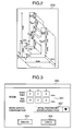
- Fig. 2 is a perspective view of a solid model to which the present invention is applied.
- Fig. 3 is a diagram showing an example of an input screen.
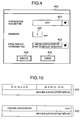
- Fig. 4 is a diagram showing another example of the input screen.
- Fig. 5 is a diagram showing another example of the input screen.
- Fig. 6 is a diagram showing an example of a data structure.
- Fig. 7 is a diagram showing another example of the input screen.
- Fig. 8 is a diagram showing another example of the data structure.
- Figs. 9A to 9C are a perspective view of a medial surface model.
- Fig. 10 is a diagram showing another example of the data structure.
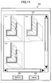
- Fig. 11 is a diagram showing another example of the input screen.
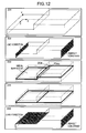
- Fig. 12 is a diagram illustrating the relation among a medial surface model, boundary conditions and constraint conditions.
-
- An analytical shell model forming apparatus according to an embodiment of the present invention will be described with reference to the accompanying drawing. In the description of this specification, an analytical shell model means a model having a defined analytical mesh, and configuration data before analytical mesh formation which data is used for forming the mesh is called a medial surface.
- Fig. 1 is a diagram showing the system structure of an analytical shell
model forming apparatus 100 according to an embodiment of the present invention. The analytical shellmodel forming apparatus 100 has an input/output unit 101 and a configurationmodel input unit 103. The input/output unit 101 has a keyboard, a pointing device and a display by which a user inputs and displays data. The configurationmodel input unit 103 registers an actual analysis target (solid model) having thickness assolid model data 102. The solid model input to the configurationmodel input unit 103 is divided into a plurality of regions, region coordinate values and a medial surface forming method are input to form a medial surface for each region, and the input values and method are registered in a region medial surface formingmethod designation unit 105 asregion designation data 104. - Input to a configuration feature medial surface forming
method designation unit 107 are a configuration feature type, a parameter and a medial surface forming method for designating the medial surface forming method for each parameter representing the configuration feature. These input data are registered as configurationfeature designation data 106. A medial surface parameterdatabase registration unit 118 registers theregion designation data 104 and configurationfeature designation data 106 in a medial surface formingparameter database 117 for each analysis content. An analysiscontent designation unit 119 selects an analysis content from the data registered in the medial surface formingparameter database 117, and resisters the corresponding region designation data and configuration feature designation data as theregion designation data 104 and configurationfeature designation data 106. - A plural medial
surface forming unit 109 forms a plurality of medial surface models from thesolid model data 102 by using a plurality of medial surface forming methods, and registers them as plural medialsurface model data 108. A medial surface modeldifference extraction unit 111 extracts a difference portion from a medial surface model group registered in the plural medialsurface model data 108, and registers it asdifference portion data 110. A difference portiondata check unit 112 compares thedifference portion data 110 with the data registered in theregion designation data 104 andconfiguration feature data 106, and registers only the coincident difference portion in thedifference portion data 110. A medial surface modelcandidate formation unit 114 generates a medial surface model by combining the coincident difference portion and thedifference portion data 110, and registers it as medialsurface model data 113. An analysis medial surfacemodel selection unit 116 selects a medial surface model to be used for analysis from the medial surfacemodel candidate data 113, and registers it as analysismedial surface model 115. In this embodiment, a plurality of medial surface forming methods are implemented in the analytical shell model forming apparatus. - An analysis result is dependent upon the medial surface. As the boundary conditions and constraint conditions of a
solid model 201 with steps shown in Fig. 12 are changed, an analysis precision and analysis time change greatly depending upon the configuration of the medial surface. For example, amedial surface model 203 having amedial surface 207 formed by connecting half points of a plate thickness of thesolid model 201 is used as an analytical medial surface model. Under theconditions 202 that a load is applied to thesolid model 201 from the left side along an X direction and the right side is perfectly constrained, a deformation different from an actual state appears at afold portion 204 of themedial model 203 as the analysis model. - This is because a force applied to the
medial surface 207 of themedial surface model 203 along the X direction is received by aflat surface 204a of thehold portion 204, although thesolid model 201 has a force receiving surface (volume) up to the constraint surface. In order to solve this problem, a newmedial surface model 205 without a step is formed. By using thismedial surface model 205, an analysis precision under the boundary conditions and constraint conditions indicated by theconditions 202 can be improved. - However, as illustrated by the
conditions 206, even if the right side perfect constraint condition is the same as theconditions 202, a bending moment action is different from that of thesolid model 201 under the condition that a load is applied to the left upper surface along a vertical direction. Namely, although the bending moment actually acts upon an intermediate portion of thesolid model 201 at which the plate thickness changes, the analysis result of themedial model 205 is that the bending moment does not act. Under theconditions 206 having such boundary and constraint conditions, the analysis precision can be improved by using themedial surface model 203. As above, the analysis precision can be improved by forming a medial surface in accordance with the analysis conditions and the like, in other words, by preparing a plurality of medial surfaces and selecting a proper one in accordance with the analysis conditions. - Next, description will be made on a specific example of forming a medial surface from the
solid model 200 shown in Fig. 2 by using the analytical shellmodel forming apparatus 100. Fig. 3 shows adisplay screen 300 of the input/output unit 101. A user inputs the coordinate values (X, Y, Z) of start and end points of a region to a region coordinatevalue designation field 301 on the operation screen. A medial surface forming method to be adopted, e.g., a "medial position point interpolation method", is input to a medial surface formingmethod designation field 302. - The user may enter directly the numerical values of the coordinate values or may designate them on a drawing by using a pointing device. A list of names of medial surface forming methods implemented in the analytical shell
model forming apparatus 100 is displayed in the list format in the medial surface formingmethod designation field 302. The user selects a proper method from this list. As an executebutton 303 is depressed, data input to the region coordinatevalue designation field 301 and medial surface formingmethod designation field 302 is registered in theregion designation data 104. As a cancelbutton 304 is depressed, the designation of the region and medial surface forming method are released. - With reference to a
display screen 400 shown in Fig. 4, description will be made on a method of inputting a configuration feature after data of theconfiguration model 201 is input. The user inputs a configuration feature type, e.g., "step", to a configuration featuretype designation field 401 by using the input/output device 101. A configuration feature parameter, in this case, "5 mm", is input to aparameter designation field 402, and the medial surface forming method to be adopted, in this case, "medial position point interpolation method", is input to a medial surface formingmethod designation field 403. - The configuration feature type is a configuration feature type capable of recognized by the analytical shell
model forming apparatus 100, and a list of configuration feature types is displayed in the list format. As an executebutton 404 is depressed, data input to the featuretype designation field 401,parameter designation field 402 and medial surface formingmethod designation field 403 is registered in the configurationfeature designation data 106. As a cancelbutton 405 is depressed, the input data is released. - Next, a medial surface forming parameter is registered in the
database 118 for each region for which the medial surface is formed. By using the input/output unit 101, the user inputs an analysis type, in this case, "configuration A collision analysis" is input to an analysistype designation field 501 on a manipulation screen shown in Fig. 5. - The data input on the configuration feature medial
surface forming screen 400 is used for the configuration feature type in the configuration featuretype designation field 502, the configuration feature parameter in theparameter designation field 503 and the medial surface forming method in the medial surface formingmethod designation field 504. Similarly, the data input on the region medialsurface forming screen 300 is used for the region coordinate values in the region coordinatevalue designation field 505 and the medial surface forming method in the medial surface formingmethod designation field 506. As an executebutton 507 is depressed, the above-described input data is registered in the medial surface formingparameter database 117. As a cancelbutton 508 is depressed, the input data is released. - With the above-described procedure, data is stored in the medial
surface parameter database 117 in the data structure shown in Fig. 6. The data in the analysistype designation field 501 on thedisplay screen 500 is stored in anarea 601, the data in the configuration featuretype designation field 502 is stored in anarea 602, the data in theparameter designation field 503 is stored in anarea 603, the data in the medial surface formingmethod designation field 504 is stored in anarea 604, the data in the region coordinatevalue designation field 505 is stored in anarea 605, and the data in the medial surface formingmethod designation field 506 is stored in anarea 606. A plurality set of the configuration feature designation data and region designation data can be registered for each analysis type. - After the data corresponding to each type of analysis is input, an actual analysis is prepared. First, the analysis type is determined. After the analysis type is determined, the analysis type is input to an analysis
type designation field 701 on adisplay screen 700 for analysis preparation start. A list of the analysistype designation field 701 is already registered in the medial surface formingparameter database 117 so that the list is selected from a pull-down menu. After the preparation is completed, an executebutton 702 is depressed. As the executebutton 702 is depressed, the region designation data and configuration feature designation data corresponding to the selected analysis type are automatically selected and input as theregion designation data 104 and configurationfeature designation data 106. As a cancelbutton 703 is depressed the input data is released. - Fig. 8 shows a specific example of the data input to the medial surface forming
parameter database 117. In this example, since "configuration A simple strength analysis", "configuration A detailed strength analysis", "configuration A collision analysis", "configuration B detailed strength analysis" and "configuration B collision analysis" have already been input as the data in the analysistype designation field 601, one of the analysis type is selected. As the "configuration A collision analysis" is selected, the following data is automatically registered in the region designation data and configuration feature designation data: - [Region designation data]
- Region 1: (0.0, 0.0, 0.0) - (13.0, 25.0, 30.0)
- Medial surface forming method 1: front side surface offset method
- Region 2: (50.0, 0.0, 0.0) - (65.0, 25.0, 30.0)
- Medial surface forming method 2: medial position point interpolation method
- [Configuration feature designation data]
- Configuration feature designation type 1: step
- Parameter 1: 5 mm
- Medial surface forming method 1: front side surface offset method
-
- Since the analysis type, medial surface forming method and the like for each region are determined, a plurality of medial surface model data sets are generated from the
solid model data 102 and registered in the plural medialsurface model data 108. Figs. 9A to 9C show several examples of the medial surface model obtained for theconfiguration model 201 shown in Fig. 2. Fig. 9A shows the medial surface model by a back side surface group offsetmethod 901, Fig. 9B shows the medial surface model by a front side surface group offsetmethod 902, and Fig. 9C shows the medial surface model by a medial positionpoint interpolation method 903. - By the back side surface group offset
method 901 shown in Fig. 9A, the solid model is divided into a plurality of thin plate portions in accordance with the back side (inner side) configuration of the solid model, and the back side surface constituting each thin plate portion of a thin plate portion group connecting the thin film portions is offset by a half of the distance corresponding to a representative plate thickness size. In this manner, the medial surface model for the thin plate portion group is formed. - More specifically,
surfaces Horizontal surfaces medial surfaces medial surfaces medial surfaces medial surfaces 941 to 943 are not changed with the medial surface forming method in the case of the configuration of this embodiment. Similarly,medial surfaces 914 to 918 of the right side portion are formed by moving the inner side surface by a half of the representative size to the right. - Conversely, by the front side surface group offset method (Fig. 9B), the thin plate group is formed on the basis of the front side surface, and the front side surface is offset by a half of the representative plate thickness size toward the inner side to form
medial surfaces medial surfaces 921 to 934 are formed by connecting points at a half of the thickness of the solid model having thickness. The generated medialsurface model data 901 to 903 are registered in the pluralmedial model data 108. - It is checked whether the medial
surface model data 901 to 903 registered in the plural medialsurface model data 108 contains the medial surfaces having the same configuration. If not contained, the medial surfaces are registered in thedifference portion data 110. For example, for the plural medialsurface model data 901 to 903 shown in Figs. 9A to 9C, themedial surfaces 905 to 934 are registered in thedifference portion data 110. - The data of each medial surface input to the
difference portion data 110 is compared with theregion designation data 104. If the compared medial surface is in the region of theregion designation data 104 and is formed by the method other than the designated medial surface forming method, then the compared medial surface data is removed from thedifference portion data 110. Similarly, the data of each medial surface input to thedifference portion data 110 is compared with the configurationfeature designation data 106. If the compared medial surface has the configuration feature type and parameter in the configurationfeature designation data 106 and is formed by the method other than the designated medial surface forming method, then the medial surface data is removed from thedifference portion data 110. - If the
medial surfaces 905 to 934 and 941 to 943 of the medialsurface model data 901 to 903 are registered in the difference portion data, ifdata 151 shown in Fig. 10 is registered in the region designation data, and ifdata 152 is registered in the configuration feature designation data, then themedial surfaces 905 to 913, 921 to 929, and 941 to 943 are removed from the difference portion. As a result, only themedial surfaces 914 to 920 and 930 to 934 are contained in the difference portion data. - Commonness of the
medial surfaces 905 to 934 constituting each of the plural medialsurface model data 901 to 903 is checked. The medial surface without commonness is registered in the difference portion data. It is therefore possible to form the medial surfacemodel candidate data 113 by combining the remaining medial surface group and the medial surface group registered in the difference portion. Fig. 11 shows examples of formed medialsurface model candidates 171 to 173. - Fig. 11 shows an example of a
display screen 160 of the input/output unit 101. A user selects one medial surface model to be used for analysis from a plurality of medialsurface model candidates 171 to 173 displayed in acandidate display field 161. In this case, the user selects a candidate from the medialsurface model candidates 171 to 173 in accordance with the analysis type. As an executebutton 162 is depressed, the selected medial surface model is registered in the analysis medialsurface model data 115. As a cancelbutton 163 is depressed, the designation is released. - According to this embodiment, if a plate thickness is relatively thin and can be approximated by a shell model even if a solid model is complicated, a medial surface for analysis suitable for the boundary conditions and constraint conditions can be used and an analysis precision can be improved. Even if the boundary conditions and constraint conditions are changed, an analysis model can be changed easily.
- According to the present invention, since the analytical shell model forming apparatus has a means for forming a plurality of medial surfaces, it is possible to use a medial surface suitable for analysis matching the analysis type and boundary conditions. It is therefore possible to shorten an analysis time and improve an analysis precision.
- It should be further understood by those skilled in the art that although the foregoing description has been made on embodiments of the invention, the invention is not limited thereto and various changes and modifications may be made without departing from the spirit of the invention and the scope of the appended claims.
Claims (6)
- An analytical shell model forming apparatus for forming an analytical shell model for numerical analysis from a solid model to be analyzed, comprising:medial surface forming means (109) for forming a plurality of medial surfaces for a same potion of the solid model;extracting means (111) for extracting a difference portion by comparing the plurality of formed medial surfaces for a same surface of the solid model;medial surface candidate model forming means (114) for forming a plurality of medial surface candidate models by using the extracted difference portion; andselecting means (116) for selecting a medial surface model to be used for analysis from the plurality of formed medial surface candidate models.
- The analytical shell model forming apparatus according to claim 1, further comprising:display means (101) for displaying the formed medial surface candidate models on a screen; andmeans (115) for registering a selected medial surface model as an analysis medial surface model.
- The analytical shell model forming apparatus according to claim 1, wherein said medial surface forming means forms a plurality of medial surfaces by using at least any one of a back side surface group offset method, a front side surface group offset method and a medial position point interpolation method.
- The analytical shell model forming apparatus according to claim 2, further comprising:wherein said display means displays on the screen a medial surface candidate model having a medial surface formed by the methods selected by said first and second selecting means.first selecting means (105) for selecting a medial surface automatic forming method to be applied to each of a plurality of regions divided from the solid model; andsecond selecting means (107) for selecting the medial surface automatic forming method to be applied to each parameter representative of a configuration feature,
- The analytical shell model forming apparatus according to claim 1, further comprising:registering means for registering a medial surface automatic forming method to be selected in accordance with an analysis type and to be applied to each of a plurality of regions divided from the solid model and the medial surface automatic forming method to be applied to each parameter representative of a configuration feature, in a database as medial surface forming parameters.
- The analytical shell model forming apparatus according to claim 5, wherein when the analysis type registered in the medial surface forming parameter database is selected, said registering means registers the medial surface automatic forming method to be applied to each region and the medial surface automatic forming method to be applied to each parameter representative of the configuration parameter, in the database as the medial surface forming parameters.
Applications Claiming Priority (2)
| Application Number | Priority Date | Filing Date | Title |
|---|---|---|---|
| JP2003343905A JP4020056B2 (en) | 2003-10-02 | 2003-10-02 | Shell model creation device for analysis |
| JP2003343905 | 2003-10-02 |
Publications (2)
| Publication Number | Publication Date |
|---|---|
| EP1521186A2 true EP1521186A2 (en) | 2005-04-06 |
| EP1521186A3 EP1521186A3 (en) | 2007-06-13 |
Family
ID=34309126
Family Applications (1)
| Application Number | Title | Priority Date | Filing Date |
|---|---|---|---|
| EP04018001A Ceased EP1521186A3 (en) | 2003-10-02 | 2004-07-29 | Analytical shell model forming apparatus |
Country Status (3)
| Country | Link |
|---|---|
| US (1) | US7363197B2 (en) |
| EP (1) | EP1521186A3 (en) |
| JP (1) | JP4020056B2 (en) |
Cited By (1)
| Publication number | Priority date | Publication date | Assignee | Title |
|---|---|---|---|---|
| WO2008149623A1 (en) * | 2007-06-06 | 2008-12-11 | Nec Corporation | Analytical model simplifying method of finite element method |
Families Citing this family (6)
| Publication number | Priority date | Publication date | Assignee | Title |
|---|---|---|---|---|
| US20060277008A1 (en) * | 2005-06-02 | 2006-12-07 | Krishnan Suresh | Analysis of boundary and/or initial value problems in thin objects and spaces |
| US20080002889A1 (en) * | 2006-06-02 | 2008-01-03 | Kenji Shimada | Systems and methods for extracting an approximated medial surface from a thin-wall solid |
| US8504337B2 (en) * | 2007-01-17 | 2013-08-06 | Caterpillar Inc. | Method and system for analyzing three-dimensional linkages |
| JP5029990B2 (en) * | 2007-11-29 | 2012-09-19 | 日本電気株式会社 | Batch processing system, batch processing method, and batch processing program |
| US8260583B2 (en) * | 2009-03-12 | 2012-09-04 | Siemens Product Lifecycle Management Software Inc. | System and method for identifying wall faces in an object model |
| JP5712796B2 (en) * | 2011-06-02 | 2015-05-07 | 富士通株式会社 | Analysis support program, analysis support method, and analysis support apparatus |
Family Cites Families (5)
| Publication number | Priority date | Publication date | Assignee | Title |
|---|---|---|---|---|
| GB2190268B (en) * | 1986-04-25 | 1990-03-28 | Toshiba Machine Co Ltd | Interactive graphic input system |
| JPH06259505A (en) | 1993-03-04 | 1994-09-16 | Mitsubishi Electric Corp | Shape simplification method |
| US6476804B1 (en) * | 2000-07-20 | 2002-11-05 | Sony Corporation | System and method for generating computer animated graphical images of an exterior patch surface layer of material stretching over an understructure |
| JP2002207777A (en) | 2001-01-10 | 2002-07-26 | Toray Ind Inc | How to generate a neutral plane model |
| US6906711B2 (en) * | 2001-02-20 | 2005-06-14 | Autodesk, Inc. | Graph-based method for multi-bodied sweep terminations |
-
2003
- 2003-10-02 JP JP2003343905A patent/JP4020056B2/en not_active Expired - Fee Related
-
2004
- 2004-07-29 EP EP04018001A patent/EP1521186A3/en not_active Ceased
- 2004-07-29 US US10/901,213 patent/US7363197B2/en not_active Expired - Fee Related
Non-Patent Citations (3)
| Title |
|---|
| ARMSTRONG C G ET AL: "Geometric processing for analysis" GEOMETRIC MODELING AND PROCESSING 2000. THEORY AND APPLICATIONS. PROCEEDINGS HONG KONG, CHINA 10-12 APRIL 2000, LOS ALAMITOS, CA, USA,IEEE COMPUT. SOC, US, 10 April 2000 (2000-04-10), pages 45-56, XP010377935 ISBN: 0-7695-0562-7 * |
| DENCACADEMIE: "PTC Product Focus: Pro/MECHANICA (Structure)" INTERNET CITATION, [Online] 14 January 2002 (2002-01-14), XP007902216 Retrieved from the Internet: URL:http://www.denc.de/carezone/archive/newsletters/011402.pdf> [retrieved on 2007-05-03] * |
| REZAYAT M: "Midsurface abstraction from 3D solid models: general theory and applications" COMPUTER AIDED DESIGN, ELSEVIER PUBLISHERS BV., BARKING, GB, vol. 28, no. 11, November 1996 (1996-11), pages 905-915, XP004022812 ISSN: 0010-4485 * |
Cited By (1)
| Publication number | Priority date | Publication date | Assignee | Title |
|---|---|---|---|---|
| WO2008149623A1 (en) * | 2007-06-06 | 2008-12-11 | Nec Corporation | Analytical model simplifying method of finite element method |
Also Published As
| Publication number | Publication date |
|---|---|
| US7363197B2 (en) | 2008-04-22 |
| JP2005108131A (en) | 2005-04-21 |
| JP4020056B2 (en) | 2007-12-12 |
| EP1521186A3 (en) | 2007-06-13 |
| US20050073519A1 (en) | 2005-04-07 |
Similar Documents
| Publication | Publication Date | Title |
|---|---|---|
| JP7423290B2 (en) | Systems and methods for customizing machined products | |
| EP3660703B1 (en) | Method, apparatus, and system for identifying device, storage medium, processor, and terminal | |
| KR102502486B1 (en) | Image generating system | |
| KR102654003B1 (en) | Image recognition device and method | |
| JP2003108609A (en) | Morphing method of structure shape, computer program thereof, and computer-readable storage medium | |
| CN1947155B (en) | Image plotting device and method thereof | |
| JP2003099482A (en) | Three-dimensional modeling system | |
| US7363197B2 (en) | Analytical shell model forming apparatus | |
| JPH09190456A (en) | Extraction method of related parts in CAD system | |
| JP4092637B2 (en) | Shape model simplification device | |
| EP1571597A2 (en) | Analysis model producing apparatus | |
| TWI844033B (en) | Computer system, dimension measurement method, and storage medium | |
| JP2006277166A (en) | 3D shape comparison program and 3D similar shape search program | |
| CN101398899B (en) | System and method for auto- recognizing metal plate part edge type | |
| JP3316818B2 (en) | Product ordering system | |
| JP2003108612A (en) | Structure shape morphing method, computer program thereof, and computer-readable storage medium | |
| JP3421082B2 (en) | CAD system | |
| US20060209070A1 (en) | Apparatus for displaying workflow, method for displaying workflow, and program for displaying workflow | |
| JPH0512386A (en) | CAE system | |
| JP2003132097A (en) | Apparatus and method for calculating deformed shape | |
| JP7479322B2 (en) | Point cloud management device and program | |
| JP2000311244A (en) | Image matching method | |
| JPH09300145A (en) | Assembleability evaluation device | |
| JP2003316832A (en) | General-purpose analysis system, general-purpose analysis processing program, and recording medium storing general-purpose analysis processing program | |
| JP2011060156A (en) | Analytic model creation support device |
Legal Events
| Date | Code | Title | Description |
|---|---|---|---|
| PUAI | Public reference made under article 153(3) epc to a published international application that has entered the european phase |
Free format text: ORIGINAL CODE: 0009012 |
|
| 17P | Request for examination filed |
Effective date: 20040816 |
|
| AK | Designated contracting states |
Kind code of ref document: A2 Designated state(s): AT BE BG CH CY CZ DE DK EE ES FI FR GB GR HU IE IT LI LU MC NL PL PT RO SE SI SK TR |
|
| AX | Request for extension of the european patent |
Extension state: AL HR LT LV MK |
|
| PUAL | Search report despatched |
Free format text: ORIGINAL CODE: 0009013 |
|
| AK | Designated contracting states |
Kind code of ref document: A3 Designated state(s): AT BE BG CH CY CZ DE DK EE ES FI FR GB GR HU IE IT LI LU MC NL PL PT RO SE SI SK TR |
|
| AX | Request for extension of the european patent |
Extension state: AL HR LT LV MK |
|
| 17Q | First examination report despatched |
Effective date: 20070725 |
|
| AKX | Designation fees paid |
Designated state(s): DE FR GB IT SE |
|
| STAA | Information on the status of an ep patent application or granted ep patent |
Free format text: STATUS: THE APPLICATION HAS BEEN REFUSED |
|
| 18R | Application refused |
Effective date: 20110805 |