EP1521062A2 - Electromagnetic flow meter - Google Patents
Electromagnetic flow meter Download PDFInfo
- Publication number
- EP1521062A2 EP1521062A2 EP04253946A EP04253946A EP1521062A2 EP 1521062 A2 EP1521062 A2 EP 1521062A2 EP 04253946 A EP04253946 A EP 04253946A EP 04253946 A EP04253946 A EP 04253946A EP 1521062 A2 EP1521062 A2 EP 1521062A2
- Authority
- EP
- European Patent Office
- Prior art keywords
- flow
- conduit
- flow meter
- electrodes
- fluid
- Prior art date
- Legal status (The legal status is an assumption and is not a legal conclusion. Google has not performed a legal analysis and makes no representation as to the accuracy of the status listed.)
- Withdrawn
Links
Images




Classifications
-
- G—PHYSICS
- G01—MEASURING; TESTING
- G01F—MEASURING VOLUME, VOLUME FLOW, MASS FLOW OR LIQUID LEVEL; METERING BY VOLUME
- G01F1/00—Measuring the volume flow or mass flow of fluid or fluent solid material wherein the fluid passes through a meter in a continuous flow
- G01F1/56—Measuring the volume flow or mass flow of fluid or fluent solid material wherein the fluid passes through a meter in a continuous flow by using electric or magnetic effects
- G01F1/58—Measuring the volume flow or mass flow of fluid or fluent solid material wherein the fluid passes through a meter in a continuous flow by using electric or magnetic effects by electromagnetic flowmeters
- G01F1/588—Measuring the volume flow or mass flow of fluid or fluent solid material wherein the fluid passes through a meter in a continuous flow by using electric or magnetic effects by electromagnetic flowmeters combined constructions of electrodes, coils or magnetic circuits, accessories therefor
Definitions
- the present invention relates to electromagnetic flow meters.
- Electromagnetic flow meters have been used for many years for measuring the flow of a conductive fluid. Electromagnetic flow meters have a number of advantages over mechanical meters as they can be made relatively compact and without moving parts to wear or become damaged by inclusions within the fluid. Electromagnetic flow meters work on the principle that a magnetic field (which may be static or time-varying) induces an EMF across a moving fluid. As a practical matter however, the EMF is typically small and measuring it with practical instruments without undue sensitivity to noise is a concern.
- water-based fluids which constitute a usefully large proportion of process fluids to be monitored, tend to have a conductivity that can be measured using an electromagnetic flowmeter of convenient dimensions.
- pure (demineralised) water has a relatively low conductivity and this may be problematic to measure as the impedance of a practically sized meter would be very high.
- measurement of pure water is rarely called for as practical fluids have much higher conductivities, tap water having a conductivity approximately 100 times greater than pure water and seawater having a conductivity approximately 10,000 times greater.
- Typical water-based process fluids have conductivities falling between the latter two.
- electromagnetic flow meters can conveniently be manufactured with practical dimensions.
- Non-polar, "insulating" fluids such as oil-based fluids are not conventionally considered suitable for use with electromagnetic flow meters and there are a wide variety of other metering techniques adapted for such fluids.
- Fluids such as turpentine have conductivities of the order of 2,500 times lower than that of tap water and 200,000 times lower than seawater. Alcohols typically have similar conductivities (or slightly higher) and fluids such as kerosene and oils have still lower conductivities.
- non-conductive fluids e.g. organic solvents, turpentine, alcohol or oil-based fluids.
- the present invention stems from an attempt by the inventors to overcome the conventional wisdom in the art that electromagnetic flow meters are fundamentally unsuited to measurement of "insulating" fluids.
- the geometry of an electromagnetic flow meter is usually tightly constrained by the physical requirements of the associated pipework, which typically means that the flow meter is formed into a cylindrical pipe of the same diameter as the surrounding pipework.
- the measuring electrodes are typically small discs. It has been considered that changing the geometry of the pipe into a non-circular section so that, for example, the proposed electrodes are closer together might reduce the impedance. However, only a small reduction can be gained (and a significant reduction would be needed) and in any event the change in shape may cause turbulence and/or other flow problems (such as increased flow resistance) and so may not be possible or may be undesirable in many applications.
- Increasing the diameter of the disc electrodes may also decrease the impedance but again only by a relatively small amount. Furthermore, as the diameter of the electrodes increases, contamination of a portion of an electrode may lead to a change in the measured potential. For this reason, it is generally considered highly desirable to keep the electrodes small in diameter. Such electrodes effectively provide a point sample of potential, which is substantially unaffected by partial contamination.
- the present invention provides an electromagnetic flow meter comprising:
- the field generating means should extend axially either side of the potential sensing electrodes in a flow meter by a sufficient amount that electrical currents primarily generated as the fluid flows into and out of the field are not generated directly in the vicinity of the potential sensing electrodes. This implies that the electrodes should be significantly shorter than the coil. Furthermore, as the length of the field generating coil increases, its resistance, weight and the cost increase, as well as the overall size of the meter, so it is generally desirable to keep the coil as small as possible and effectively use point electrodes, as discussed above.
- conduit diameter are intended to encompass the appropriate cross-sectional distance (or geometric mean of height and width) of a non-circular conduit.
- elongate electrodes which preferably have a length in the direction of flow substantially greater than the electrode dimension in a perpendicular direction, preferably at least twice and in embodiments typically as much as at least five, preferably at least ten and more preferably of the order of twenty times the perpendicular dimension.
- the electrodes have a length in the direction of elongation of the fluid conduit at least equal to the conduit diameter (or separation of electrodes or equivalent cross-sectional dimension of a non-circular conduit).
- the electrodes preferably have a length similar to the length of the field generating means, preferably at least half the length of the field generating means, preferably at least three quarters, typically at least 80%, ideally of the order of 90% or more of the length of the field generating means.
- Such a flow meter may be reliably capable of measuring flow in a fluid having conductivity of the order of 10 -4 mhos/m or less without the requirement for specialist instrumentation and without being unduly susceptible to noise.
- the flow meter further comprises an input amplifier connected to the potential sensing electrodes having an input impedance of at least 10 12 ohms, more preferably of the order of 10 15 ohms or more.
- the invention provides an electromagnetic flow meter comprising an elongate flow conduit having a length along a first direction corresponding to a direction of flow through the conduit, a width in a second direction substantially perpendicular to the first direction and a height in a third direction substantially orthogonal to the first and second directions; at least a first field generating coil positioned above the flow conduit for generating a magnetic field substantially along said third direction; first and second potential sensing electrodes positioned at opposite sides across the conduit for sensing potential developed across the conduit width; wherein both the field generating coil and the first and second electrodes are elongate along said first direction.
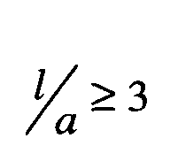
- the field generating coil has a length in the first direction at least 3 times as long as the geometric mean of the height and width of the conduit.
- the first and second electrodes have a length in the first which is similar to, but slightly less than, the length of the field generating coil. References to height, width, above and across are for convenience and are not intended to imply any spatial orientation.
- the flow meter has a second field generating coil opposite the first field generating coil.
- the conduit may be circular in cross-section in which case, the height and width (and geometric mean thereof) are all equal to the diameter of the conduit.
- the electromagnetic flow meter preferably has an input amplifier for measuring the potential across the first and second electrodes having an input impedance of at least 10 12 ohms and preferably 10 15 ohms or more.
- the invention further provides an electromagnetic flow meter adapted and arranged to obtain a measurement of flow of a fluid having a conductivity of the order of 10 -4 mhos/m or less.
- the invention further provides an electromagnetic flow meter adapted and arranged to obtain a measure of flow in an oil-based fluid.
- the invention further provides an oil, alcohol, turpentine or other organic fluid (preferably oil) flow meter comprising an electromagnetic flow meter having an elongate field generating means and elongate potential sensing electrodes and a high impedance input amplifier for measuring a potential generated across the fluid to derive a measure of flow therefrom.
- an oil, alcohol, turpentine or other organic fluid (preferably oil) flow meter comprising an electromagnetic flow meter having an elongate field generating means and elongate potential sensing electrodes and a high impedance input amplifier for measuring a potential generated across the fluid to derive a measure of flow therefrom.
- the invention further provides a method of deriving a measure of flow of a fluid having a conductivity of the order of 10 -4 mhos/m and/or an oil-based fluid, the method comprising passing the fluid through an electromagnetic flowmeter having an elongate field generating coil and elongate potential sensing electrodes and deriving a measure of flow from a potential sensed by the potential sensing electrodes using a high impedance amplifier.
- a magnetic flow meter is in essence a type of M.H.D. (magneto-hydrodynamic) generator.
- a simple form consists of a duct, lined with an electrically insulating lining through which the fluid to be measured flows, and in operation the fluid is made to pass through a transverse magnetic field within the duct.
- the moving fluid creates an electric field, E in a direction perpendicular to the motion, and to the magnetic field.
- the strength of the electric field depends upon the velocity V, and upon the intensity of the field B.
- Appropriately placed electrodes are connected to electronic apparatus that measures the potential difference between them and converts this into a form that indicates the mean flow through the meter.
- the details of the electronic apparatus are not germane and many conventional schemes are known which may be used herein.
- the sensing electrodes are conventionally kept small and far from the ends of the coil, to minimize the unpredictable effects of these currents. This simple expedient simplifies conventional analysis and is normally sufficient for practical meters. However, pursuant to the invention, further analysis has been carried out, and this will now be detailed.
- current flows in a positive direction throughout the field region and returns in the other direction at the ends of the meter.
- the device as an M.H.D. generator having a source impedance R s associated with the field region and a built in load R e attributable to the circulating currents at each end.
- R s source impedance
- R e built in load
- the equivalent circuit is shown in figure 4.
- the input to this circuit would be V z B x a whilst the output from the electrodes would be S ⁇ V z B x a where the sensitivity S is R e / R e + R s .
- Equation (1) we have used equation (1) to derive the current density within the duct and then, by integration, calculate the total current that circulates. Since we know that the maximum driving voltage is V z B x a we have calculated the total resistance ( R e + R s ) in the circuit.
- Figure 5 shows the total resistance plotted against l/a. For short meters we anticipated that R s would be 1 / ⁇ a / wl . This resistance ( R s based on geometry) is also shown on the graph. It can be seen that for very short meters the total resistance in the circuit tends towards this geometric value whereas as I/a becomes large the resistance becomes constant and is about 2.691 / ⁇ w . From this we have concluded that for long meters the resistance will, unlike a conventional practical meter, be solely determined by the currents that circulate at the ends of the meter (which currents do not normally feature in a conventional meter). From consideration of the equivalent circuit shown in figure 4 it can be seen that as R e becomes large compared with R s the sensitivity tends towards unity.
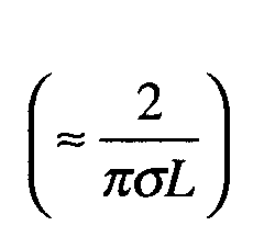
- the output impedance of a conventionally arranged meter fitted with small circular "point contact" electrodes is 1 / ⁇ d (but we have found that 2 / ⁇ d may be more accurate), where d is the diameter of the electrode.
- This resistance, R o appears in the equivalent circuit as shown in Figure 6.
- R e which is not normally considered
- Figure 7 shows the electric potential and the current distribution for a meter where l/a is 3.
- l/a 3
- E - V ⁇ B
- the sensitivity S is now unity. Eddy currents still circulate at the ends of the instrument but they no longer have any effect upon the potential at the electrodes.
- the equivalent circuits shown in figures 4 and 6 which effectively model a conventional meter no longer have any meaning. This is because the source impedance is not meaningfully associated with the length of the field region within the meter.
- the output impedance is therefore dictated by the electrode geometry and the eddy currents do not cause the anticipated problems.
- the fluid to be measured is an alcohol with an electrical conductivity of 0.13e-6 mhos/m (0.0013uS/cm).
- the length of the field region will be 0.045m and the source impedance of the magneto-hydrodynamic (MHD) generator within the meter will be about which is 54.7 M ⁇ .
- the total impedance is of the order of 1000 M ⁇ . It is difficult to measure signals with such an impedance without electrical noise causing problems.
- a further problem with low conductivity liquids is that minor static charges do not dissipate rapidly and will cause triboelectric noise as they pass the electrodes and, with such high impedance, this will be significant.
- the electrodes are still 8mm wide, but in this case the elongate electrodes are 240mm long (30 times the height) and the magnetic field extends over a (similar) length of 270mm.
- the meter bore is 50mm, so the electrodes and coil are about 5 diameters long.
- the effect of using a long meter with elongate electrodes is that the electrode impedance and the source impedance are both significantly reduced.
- a further advantage we have found is that the use of long electrodes is an effective way of reducing both the flow induced noise and the electrical noise.
- small static charges may still remain in low conductivity fluids but, because the electrodes are long in the direction of flow, noise from any charges tends to average out.
- magnetic flow meters having a field region several diameters long and which are equipped with elongate electrodes are significantly better at measuring the flow of liquids whose electrical conductivity is low.
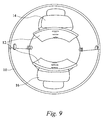
- a housing and magnetic return circuit 10 typically formed from steel, houses pole pieces 12, upper coil 14 and lower coil 16.
- the housing has an insulating lining 22, here formed from nitrile rubber, defining a bore (here 50mm diameter) in which are provided opposed sensing electrodes 18.
- the coils are oriented about a vertical axis and the sensing electrodes are positioned across the horizontal diagonal although of course the spatial orientation is not critical.
- Optional earthing electrodes 20 are positioned along the coil axis (where they will not pick up an induced emf due to the coil).
- the electrodes 18,20 and coils 14,16 are connected to metering electronics in housing 24.
- the metering electronics can be largely conventional and will not be described or depicted in detail. However, it is important to note that a very high impedance input amplifier should be used, preferably 10 15 ohms, which can be provided by a commercially available FET input operational amplifier.
- the elongate electrodes are long along the direction of flow (here 480mm long) but of typically relatively small dimensions (here 8mm) high (in the perpendicular dimension).
- the thickness of the electrodes is not critical but here they are formed as an approximately semi-circular section for structural rigidity.
- an excitation field typically time varying, e.g. AC or pulsed DC or a more complex scheme is applied by applying a current to the coils 14,16 and the potential induced in the moving fluid (here alcohol) is measured using a high impedance differential amplifier connected to sensing electrodes 18. After appropriate scaling and calibration, a measure of flow is obtained from the sensed potential.
- the impedance can be reduced further proportionately by extending the meter.
- the meter can be made very long, installed into several meters of pipe. Making the electrodes long is not problematic and a long liner can be extruded. However, making a long coil introduces some practical concerns.
- One solution is to extrude the pole pieces. Winding the coil around such a long pole piece cannot be done with unmodified conventional coil winding equipment but is nonetheless susceptible to automation using a moving shuttle and can of course be done manually. Alternatively, a modular coil construction may be adopted, particularly if the coil has a small number of turns which plug together - this may be acceptable if a relatively large current is passed through relatively few turns.
- the electrode impedance is inversely proportional to the length of the electrode
- the source impedance of the MHD generator is inversely proportional to the length of the coil.
- the length of the electrode is approximately equal to the length of the coil, and thus the total impedance is approximately inversely proportional to the length of the coil.
- the total impedance is also inversely proportional to the conductivity of the fluid.
- an appropriate length for the coil can be determined based on the conductivity of the fluid, in order to obtain a total impedance below a desired threshold and allow a successful flow measurement to be made.
- a fluid with a lower conductivity will require a longer coil in a practical device. Very long coils and field regions can be produced using the techniques suggested above if required.
Landscapes
- Physics & Mathematics (AREA)
- Electromagnetism (AREA)
- Fluid Mechanics (AREA)
- General Physics & Mathematics (AREA)
- Measuring Volume Flow (AREA)
Abstract
Description
The present invention, however, is based on a different approach.
at least a first field generating coil positioned above the flow conduit for generating a magnetic field substantially along said third direction;
first and second potential sensing electrodes positioned at opposite sides across the conduit for sensing potential developed across the conduit width;
wherein both the field generating coil and the first and second electrodes are elongate along said first direction.
References to height, width, above and across are for convenience and are not intended to imply any spatial orientation.


Claims (16)
- An electromagnetic flow meter comprising:characterised in that both the field generating means and the potential sensing electrodes are elongate in the direction of flow.an elongate flow conduit having a direction of elongation corresponding to a direction of fluid flow;magnetic field generating means for generating a magnetic field across the flow conduit;potential sensing electrodes for sensing a potential generated by the magnetic field in a fluid flowing through the conduit;
- A flow meter according to Claim 1 wherein the electrodes are longer than twice the mean conduit cross-sectional dimension, preferably at least three times, more preferably at least five times said dimension.
- A flow meter according to Claim 1 or 2 wherein the elongate electrodes have a length in the direction of flow substantially greater than the electrode dimension in a perpendicular direction.
- A flow meter according to Claim 3 wherein the electrode length in the direction of flow is at least twice the perpendicular dimension, preferably at least five times, more preferably at least ten times the perpendicular dimension.
- A flow meter according to any preceding claim wherein the electrodes have a length in the direction of elongation of the fluid conduit at least equal to the mean conduit cross-sectional dimension.
- A flow meter according to any preceding claim wherein the length of the electrodes is at least half the length of the field generating means.
- A flow meter according to any preceding claim arranged to measure flow in a fluid having conductivity of the order of 10-4 mhos/m or less.
- A flow meter according to any preceding claim further comprising an input amplifier connected to the potential sensing electrodes having an input impedance of at least 1012 ohms, more preferably of the order of 1015ohms.
- An electromagnetic flow meter comprising an elongate flow conduit having a length along a first direction corresponding to a direction of flow through the conduit, a width in a second direction substantially perpendicular to the first direction and a height in a third direction substantially orthogonal to the first and second directions;
at least a first field generating coil positioned above the flow conduit for generating a magnetic field substantially along said third direction;
first and second potential sensing electrodes positioned at opposite sides across the conduit for sensing potential developed across the conduit width;
wherein the field generating coil has a length in the first direction at least as long as the geometric mean of the height and width of the conduit and wherein the first and second electrodes also have a length in the first direction substantially greater than the height of the electrodes in the third direction and preferably at least as long as the geometric mean of the height and width of the conduit. - A flow meter according to Claim 9 having a second field generating coil opposite the first field generating coil.
- A flow meter according to any preceding claim wherein the conduit is substantially circular in cross-section.
- An electromagnetic flow meter adapted and arranged to obtain a measurement of flow of a fluid having a conductivity of the order of 10-4 mhos/m or less.
- An electromagnetic flow meter adapted and arranged to obtain a measure of flow in an oil-based fluid.
- An oil, turpentine or organic fluid flow meter comprising an electromagnetic flow meter having an elongate field generating means and elongate potential sensing electrodes and a high impedance input amplifier for measuring a potential generated across the fluid to derive the measure of flow therefrom.
- An electromagnetic flow meter comprising means deriving a measure of flow from a quantity of oil flowing through an elongate metering conduit of the flowmeter.
- A method of deriving a measure of flow of a fluid having a conductivity of the order of 10-4mhos/m and/or an oil-based fluid, the method comprising passing the fluid through an electromagnetic flow meter having an elongate field generating coil and elongate potential sensing electrodes and deriving a measure of flow from a potential sensed by the potential sensing electrodes using a high impedance amplifier.
Applications Claiming Priority (2)
| Application Number | Priority Date | Filing Date | Title |
|---|---|---|---|
| GB0315271 | 2003-06-30 | ||
| GB0315271A GB2403542B (en) | 2003-06-30 | 2003-06-30 | Electromagnetic flow meter |
Publications (2)
| Publication Number | Publication Date |
|---|---|
| EP1521062A2 true EP1521062A2 (en) | 2005-04-06 |
| EP1521062A3 EP1521062A3 (en) | 2007-03-21 |
Family
ID=27676359
Family Applications (1)
| Application Number | Title | Priority Date | Filing Date |
|---|---|---|---|
| EP04253946A Withdrawn EP1521062A3 (en) | 2003-06-30 | 2004-06-30 | Electromagnetic flow meter |
Country Status (3)
| Country | Link |
|---|---|
| US (1) | US7117749B2 (en) |
| EP (1) | EP1521062A3 (en) |
| GB (1) | GB2403542B (en) |
Cited By (1)
| Publication number | Priority date | Publication date | Assignee | Title |
|---|---|---|---|---|
| CN111238586A (en) * | 2020-03-27 | 2020-06-05 | 上海市计量测试技术研究院 | Electromagnetic flowmeter for measuring low electrical conductivity and its rate measuring method |
Families Citing this family (12)
| Publication number | Priority date | Publication date | Assignee | Title |
|---|---|---|---|---|
| GB2440964B (en) * | 2006-08-18 | 2011-08-10 | Abb Ltd | Flow meter |
| GB2440963B (en) * | 2006-08-18 | 2011-06-08 | Abb Ltd | Flow meter |
| DE102007014469A1 (en) * | 2007-03-22 | 2008-09-25 | Endress + Hauser Flowtec Ag | A method for predictive maintenance and / or method for determining the electrical conductivity in a magnetic inductive flowmeter |
| DE102007015368A1 (en) * | 2007-03-28 | 2008-10-02 | Endress + Hauser Flowtec Ag | Method for operating a magnetic-inductive flowmeter |
| JP4920518B2 (en) * | 2007-07-19 | 2012-04-18 | 大同メタル工業株式会社 | Oil-air lubrication system |
| DE102009021430A1 (en) * | 2009-05-15 | 2010-11-18 | Doll, Friedhelm, Dipl.-Ing. | Magnetic-inductive flow meter, has magnetic arrangement comprising magnets i.e. permanent magnets, and elongated magnetizable bar, and electrodes comprise opposite distance in longitudinal direction of tube |
| EP2383548A1 (en) * | 2010-04-29 | 2011-11-02 | Zylum Beteiligungsgesellschaft mbH & Co. Patente II KG | Measuring device and method for measuring the flow speed of a medium flowing through a measuring tube |
| WO2012018962A1 (en) | 2010-08-03 | 2012-02-09 | Lee Gouwens | Electromagnetic flow meter |
| US8434371B2 (en) | 2010-10-14 | 2013-05-07 | Brickhouse Innovations, Llc | Electromagnetic fluid velocity sensor with adjustable electrodes |
| CN102980617A (en) * | 2012-12-21 | 2013-03-20 | 上海一诺仪表有限公司 | Anti-high-frequency electromagnetic interference device for electromagnetic flow meter |
| RU2654966C1 (en) * | 2017-07-11 | 2018-05-23 | Акционерное общество "Научно-исследовательский институт теплоэнергетического приборостроения" АО "НИИТеплоприбор" | Electromagnetic method to measure the low rate of a liquid metal |
| NO347033B1 (en) * | 2020-06-12 | 2023-04-24 | Roxar Flow Measurement As | Flow meter for measuring flow velocity in oil continuous flows |
Family Cites Families (10)
| Publication number | Priority date | Publication date | Assignee | Title |
|---|---|---|---|---|
| US3274831A (en) * | 1965-04-14 | 1966-09-27 | Vincent J Cushing | Electromagnetic flowmeter |
| DE2225356C2 (en) * | 1972-05-25 | 1982-04-15 | Interatom Internationale Atomreaktorbau Gmbh, 5060 Bergisch Gladbach | Flow meter for electrically conductive liquids |
| US3839912A (en) * | 1973-01-18 | 1974-10-08 | Fischer & Porter Co | Metering electrode assembly for electromagnetic flowmeters |
| DE2816796A1 (en) * | 1978-04-18 | 1979-10-25 | Fischer & Porter Gmbh | MAGNETIC INDUCTIVE FLOW METER |
| DE3013035A1 (en) * | 1979-04-05 | 1980-10-23 | Nat Res Dev | METHOD FOR ELECTROMAGNETIC FLOW MEASUREMENT AND WORKING FLOW MEASURING DEVICE |
| US5289725A (en) * | 1991-07-31 | 1994-03-01 | The Foxboro Company | Monolithic flow tube with improved dielectric properties for use with a magnetic flowmeter |
| DE4239956C2 (en) * | 1991-11-29 | 1997-05-07 | Hitachi Ltd | Electromagnetic flow meter |
| US6973840B2 (en) * | 1999-10-06 | 2005-12-13 | Cushing Vincent J | Comprehensive electromagnetic flowmeter |
| WO2004070323A1 (en) * | 2003-02-10 | 2004-08-19 | Gambro Lundia Ab | A flow sensor and method for measuring a flow rate component of a fluid containing electrically charged elements |
| GB2403016B (en) * | 2003-06-17 | 2007-02-21 | Abb Ltd | Electromagnetic flow meter |
-
2003
- 2003-06-30 GB GB0315271A patent/GB2403542B/en not_active Expired - Fee Related
-
2004
- 2004-06-18 US US10/871,268 patent/US7117749B2/en not_active Expired - Fee Related
- 2004-06-30 EP EP04253946A patent/EP1521062A3/en not_active Withdrawn
Cited By (1)
| Publication number | Priority date | Publication date | Assignee | Title |
|---|---|---|---|---|
| CN111238586A (en) * | 2020-03-27 | 2020-06-05 | 上海市计量测试技术研究院 | Electromagnetic flowmeter for measuring low electrical conductivity and its rate measuring method |
Also Published As
| Publication number | Publication date |
|---|---|
| GB2403542B (en) | 2006-11-01 |
| GB2403542A (en) | 2005-01-05 |
| GB0315271D0 (en) | 2003-08-06 |
| US7117749B2 (en) | 2006-10-10 |
| EP1521062A3 (en) | 2007-03-21 |
| US20050109120A1 (en) | 2005-05-26 |
Similar Documents
| Publication | Publication Date | Title |
|---|---|---|
| US7117749B2 (en) | Electromagnetic flow meter for low conductivity fluids | |
| JP3263296B2 (en) | Electromagnetic flow meter | |
| US2733604A (en) | coulter | |
| RU2615205C2 (en) | Magnetic flowmeter with multiple coils | |
| EP0416866B1 (en) | Electromagnetic flowmeter utilizing magnetic fields of a plurality of frequencies | |
| US6414493B1 (en) | Toroid conductivity sensor | |
| CN1264464A (en) | Electromagnetic flowmeter | |
| JP6272500B2 (en) | Improved magnetic core configuration for magnetic flowmeters | |
| CN101189492A (en) | Magnetic flowmeter with monolithic construction and conductive polymer electrodes | |
| TW202108988A (en) | Magnetic flowmeter with media conductivity measurement | |
| DE1944979U (en) | INDUCTIVE FLOW METER TO BE MOUNTED ON THE SIDE. | |
| EP1431716A1 (en) | Electromagnetic flowmeter | |
| US7415892B2 (en) | Disposable flow chamber electro-magnetic flow sensor | |
| EP4298407B1 (en) | Apparatus for monitoring fluid flow in a pipe using electromagnetic velocity tomography | |
| RU2030713C1 (en) | Electromagnetic flow meter | |
| CN115031795A (en) | Fluid parameter measuring method and system and multi-parameter electromagnetic flowmeter | |
| CA1304602C (en) | Apparatus for and method of determining liquid flow in open channels and conduits | |
| CN101194147A (en) | Magnetic induction flowmeter and measuring tube for such a flowmeter | |
| CN111578895B (en) | Sedimentation monitoring method for magnetorheological fluid in magnetorheological damping device | |
| US20200309577A1 (en) | Magnetic Flowmeter with Enhanced Signal/Noise Ratio | |
| EP3628982A1 (en) | Full bore magnetic flowmeter assembly | |
| US3040571A (en) | Electromagnetic flowmeter for conductive fluids | |
| DE10116776A1 (en) | Magnetic induction flow-meter for measuring the mean fluid flow rate of an electrically conducting fluid, e.g. used or sewage water in a sewage-treatment plant, that can be used with steel armored pipes and large diameter pipes | |
| JP2001281028A (en) | Electromagnetic flow meter | |
| RU2252397C1 (en) | Inductive level meter |
Legal Events
| Date | Code | Title | Description |
|---|---|---|---|
| PUAI | Public reference made under article 153(3) epc to a published international application that has entered the european phase |
Free format text: ORIGINAL CODE: 0009012 |
|
| AK | Designated contracting states |
Kind code of ref document: A2 Designated state(s): AT BE BG CH CY CZ DE DK EE ES FI FR GB GR HU IE IT LI LU MC NL PL PT RO SE SI SK TR |
|
| AX | Request for extension of the european patent |
Extension state: AL HR LT LV MK |
|
| PUAL | Search report despatched |
Free format text: ORIGINAL CODE: 0009013 |
|
| AK | Designated contracting states |
Kind code of ref document: A3 Designated state(s): AT BE BG CH CY CZ DE DK EE ES FI FR GB GR HU IE IT LI LU MC NL PL PT RO SE SI SK TR |
|
| AX | Request for extension of the european patent |
Extension state: AL HR LT LV MK |
|
| 17P | Request for examination filed |
Effective date: 20070920 |
|
| AKX | Designation fees paid |
Designated state(s): AT BE BG CH CY CZ DE DK EE ES FI FR GB GR HU IE IT LI LU MC NL PL PT RO SE SI SK TR |
|
| 17Q | First examination report despatched |
Effective date: 20110620 |
|
| STAA | Information on the status of an ep patent application or granted ep patent |
Free format text: STATUS: THE APPLICATION IS DEEMED TO BE WITHDRAWN |
|
| 18D | Application deemed to be withdrawn |
Effective date: 20111101 |