EP1521041A1 - Outdoor unit of air conditioner - Google Patents
Outdoor unit of air conditioner Download PDFInfo
- Publication number
- EP1521041A1 EP1521041A1 EP03736316A EP03736316A EP1521041A1 EP 1521041 A1 EP1521041 A1 EP 1521041A1 EP 03736316 A EP03736316 A EP 03736316A EP 03736316 A EP03736316 A EP 03736316A EP 1521041 A1 EP1521041 A1 EP 1521041A1
- Authority
- EP
- European Patent Office
- Prior art keywords
- outdoor unit
- connecting port
- valve
- refrigerant communication
- liquid
- Prior art date
- Legal status (The legal status is an assumption and is not a legal conclusion. Google has not performed a legal analysis and makes no representation as to the accuracy of the status listed.)
- Granted
Links
Images




Classifications
-
- F—MECHANICAL ENGINEERING; LIGHTING; HEATING; WEAPONS; BLASTING
- F24—HEATING; RANGES; VENTILATING
- F24F—AIR-CONDITIONING; AIR-HUMIDIFICATION; VENTILATION; USE OF AIR CURRENTS FOR SCREENING
- F24F5/00—Air-conditioning systems or apparatus not covered by F24F1/00 or F24F3/00, e.g. using solar heat or combined with household units such as an oven or water heater
-
- F—MECHANICAL ENGINEERING; LIGHTING; HEATING; WEAPONS; BLASTING
- F24—HEATING; RANGES; VENTILATING
- F24F—AIR-CONDITIONING; AIR-HUMIDIFICATION; VENTILATION; USE OF AIR CURRENTS FOR SCREENING
- F24F1/00—Room units for air-conditioning, e.g. separate or self-contained units or units receiving primary air from a central station
- F24F1/06—Separate outdoor units, e.g. outdoor unit to be linked to a separate room comprising a compressor and a heat exchanger
- F24F1/26—Refrigerant piping
- F24F1/32—Refrigerant piping for connecting the separate outdoor units to indoor units
-
- F—MECHANICAL ENGINEERING; LIGHTING; HEATING; WEAPONS; BLASTING
- F24—HEATING; RANGES; VENTILATING
- F24F—AIR-CONDITIONING; AIR-HUMIDIFICATION; VENTILATION; USE OF AIR CURRENTS FOR SCREENING
- F24F1/00—Room units for air-conditioning, e.g. separate or self-contained units or units receiving primary air from a central station
- F24F1/06—Separate outdoor units, e.g. outdoor unit to be linked to a separate room comprising a compressor and a heat exchanger
- F24F1/26—Refrigerant piping
-
- F—MECHANICAL ENGINEERING; LIGHTING; HEATING; WEAPONS; BLASTING
- F24—HEATING; RANGES; VENTILATING
- F24F—AIR-CONDITIONING; AIR-HUMIDIFICATION; VENTILATION; USE OF AIR CURRENTS FOR SCREENING
- F24F1/00—Room units for air-conditioning, e.g. separate or self-contained units or units receiving primary air from a central station
- F24F1/06—Separate outdoor units, e.g. outdoor unit to be linked to a separate room comprising a compressor and a heat exchanger
- F24F1/56—Casing or covers of separate outdoor units, e.g. fan guards
Definitions
- the present invention relates to an outdoor unit for an air conditioner. More specifically, the present invention relates to an air conditioner outdoor unit that is connected to indoor units by means of a gaseous refrigerant communication pipe and a liquid refrigerant communication pipe.
- split-type systems having an indoor unit and an outdoor unit connected by communication pipes are widely used.
- the outdoor unit is installed on the roof or other location and the indoor units are installed in the ceiling or other location of each floor, the outdoor unit and indoor units being connected together by a gaseous refrigerant pipe and a liquid refrigerant pipe to form a refrigerant circuit.
- the outdoor unit of such an air conditioning system has a gas-side shut-off valve and a liquid-side shut-off valve at the terminal ends of the refrigerant circuit therewithin. These shut-off valves are switched from the closed state to the open state after the outdoor unit and the indoor units have been installed onsite and the gaseous refrigerant pipe and liquid refrigerant pipe from the indoor units are connected. As a result, refrigerant can flow between the outdoor unit and the indoor units.
- the gas-side shut-off valve 118 and the liquid-side shut-off valve 119 of the outdoor unit 102 are arranged side by side along the front panel 121 of the casing as shown in Figure 7 or in front of and in rear of each other along the side panel 122 of the casing (not shown). Since the two shut-off valves 118, 119 are closely adjacent to each other, it is easier to complete the work of applying thermally insulating tape to the gaseous refrigerant pipe and liquid refrigerant pipe, which are connected to the pipe connecting ports 118a, 119a of the shut-off valves 118, 119 and drawn out of the outdoor unit, and the work of covering the valve area with a decorative metal plate.
- the object of the present invention is to reduce interference between the refrigerant pipes connected to the outdoor unit of an air conditioning system both in cases in which the refrigerant pipes are drawn out in a direction parallel to the depth dimension of the outdoor unit (hereinafter described as “the depthwise direction”) and in cases in which the refrigerant pipes are drawn out in a direction parallel to the width dimension of the outdoor unit (hereinafter described as “the widthwise direction”).
- the air conditioner outdoor unit of claim 1 is an air conditioner outdoor unit that is connected to indoor units by means of a gaseous refrigerant communication pipe and a liquid refrigerant communication pipe and is provided with a gas-side shut-off valve and a liquid-side shut-off valve.
- the gas-side shut-off valve has a first connecting port to which the gaseous refrigerant communication pipe is connected.
- the liquid-side shut-off valve has a second connecting port to which the liquid refrigerant communication pipe is connected.
- the first connecting port and second connecting port are offset from each other in both the depthwise direction and the widthwise direction.
- the first connecting port and second connecting port are aligned in either the depthwise direction or the widthwise direction. Consequently, when the connecting ports are aligned in the depthwise direction, the refrigerant communication pipes will interfere with each other if they are drawn out in the depthwise direction at the same height from the connecting ports. Meanwhile, when the connecting ports are aligned in the widthwise direction, the refrigerant communication pipes will interfere with each other if they are drawn out in the widthwise direction at the same height from the connecting ports.
- the first connecting port and second connecting port are offset from each other in both the depthwise direction and the widthwise direction in a plan view. Since the connecting ports are offset by a sufficient amount such that the refrigerant communication pipes do not interfere with each other in a plan view when they are drawn out from the connecting ports in the depthwise direction or in the widthwise direction, the refrigerant communication pipes will not interfere with each other in cases where the refrigerant communication pipes are drawn out at the same height in the depthwise direction or cases where the refrigerant communication pipes are drawn out at the same height in the widthwise direction.
- an outdoor unit in accordance with this claim makes it possible to avoid interference between the refrigerant communication pipes connected to the shut-off valves both in cases where the refrigerant communication pipes are drawn out in the depthwise direction and in cases where the refrigerant communication pipes are drawn out in the widthwise direction.
- the air conditioner outdoor unit of claim 2 is an air conditioner outdoor unit in accordance with claim 1, wherein the first connecting port and the second connecting port face in the same direction.
- the refrigerant communication pipes drawn out from the connecting ports can be thermally insulated and covered more easily. Also, the refrigerant communication pipes connected to the shut-off valves can be installed without interfering with each other when they are drawn out in the depthwise direction or in the widthwise direction. As a result, the amount of curved portions of the refrigerant communication pipes can be held to a minimum.
- the air conditioner outdoor unit of claim 3 is an air conditioner outdoor unit in accordance with claim 1 or 2, wherein the first connecting port and second connecting port are offset from each other in the depthwise and widthwise directions in such a manner that the gaseous and liquid refrigerant communication pipes connected to the connecting ports do not interfere with each other when they are drawn out in the depthwise direction with their widthwise positions maintained constant and their height positions arranged such that they overlap partially in a side view.
- first connecting port and second connecting port are offset from each other in the depthwise and widthwise directions in such a manner that the gaseous and liquid refrigerant communication pipes connected to the connecting ports do not interfere with each other even when they are drawn out in the widthwise direction with their depthwise positions maintained constant and their height positions arranged such that they overlap partially in a side view.
- first connecting port and second connecting port are offset from each other in the depthwise and widthwise directions, work associated with bending the pipes and using pipe joints in order to avoid interference between the refrigerant communication pipes can be held to a minimum.
- the pipe layout can be made more compact (occupy less space) in the height direction and in the widthwise or depthwise direction. This kind of arrangement is particular effective when the two refrigerant communication pipes have different pipe diameters.
- the air conditioner outdoor unit of claim 4 is an air conditioner outdoor unit in accordance with claim 1 or 2, wherein the first connecting port and second connecting port are offset from each other in the depthwise and widthwise directions in such a manner that the gaseous and liquid refrigerant communication pipes connected to the connecting ports do not interfere with each other even when they are drawn out in the depthwise direction with their widthwise positions maintained constant and their height positions the same. Furthermore, the first connecting port and second connecting port are offset from each other in the depthwise and widthwise directions in such a manner that the gaseous and liquid refrigerant communication pipes connected to the connecting ports do not interfere with each other even when they are drawn out in the widthwise direction with their depthwise positions maintained constant and their height positions the same.
- first connecting port and second connecting port are amply offset from each other in the depthwise and widthwise directions, work associated with bending the pipes and using pipe joints in order to avoid interference between the refrigerant communication pipes can be held to a minimum.
- the air conditioner outdoor unit of claim 5 is an air conditioner outdoor unit in accordance with any one of claims 1 to 4, wherein the first connecting port and the second connecting port are offset by approximately the same distance in both the depthwise direction and the widthwise direction.
- first connecting port and second connecting port are offset by approximately the same distance in the depthwise direction as in the widthwise direction, interference between refrigerant communication pipes drawn out in the depthwise or widthwise direction can be suppressed while reducing the relative distance between the first connecting port and the second connecting port and reducing the space occupied by the gas-side shut-off valve and the liquid-side shut-off valve.
- first connecting port and second connecting port are offset by approximately the same distance in the depthwise and widthwise directions, in a plan view a straight line joining the centers of the two connecting ports is oriented at approximately a 45-degree angle with respect to the panel oriented in the depthwise direction and the panel oriented in the widthwise direction.
- the air conditioner outdoor unit of claim 6 is an air conditioner outdoor unit in accordance with any one of claims 1 to 5, wherein the first connecting port and the second connecting port face both face downward.
- An air conditioner outdoor unit in accordance with claim 6 is also provided with a box-shaped casing and bottom-raising members.
- the casing covers the gas-side shut-off valve and the liquid-side shut-off valve, and the casing has an opening below the gas-side shut-off valve and the liquid-side shut-off valve.
- the bottom-raising members serve to secure space between the surface on which the outdoor unit is to be installed and the bottom panel of the casing.
- this claim makes it easier to improve the external appearance of the outdoor unit by passing the refrigerant communication pipes in the space under the casing.
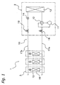
- FIG. 1 shows the refrigerant circuit of an air conditioning system that includes an air conditioner outdoor unit in accordance with an embodiment of the present invention.
- the air conditioning system 1 is a multiple-type air conditioning system for office buildings having one outdoor unit 2 and a plurality of indoor units 3 connected in parallel.
- the refrigerant circuit 10 of the air conditioning system 1 includes a compressor 11, a four-way selector valve 12, an outdoor heat exchanger 13, an outdoor expansion valve 14, indoor expansion valves 15, and the indoor heat exchangers 16 connected in sequence and is configured to perform a vapor compression type refrigeration cycle.
- the compressor 11, four-way selector valve 12, outdoor heat exchanger 13, and outdoor expansion valve 14 are contained in the outdoor unit 2 and the indoor expansion valves 15 and indoor heat exchangers 16 are contained in the indoor units 3.
- the four-way selector valve 12 and the indoor heat exchangers 16 are connected by a gaseous refrigerant communication pipe 17a and the outdoor expansion valve 14 and the indoor expansion valves 15 are connected by a liquid refrigerant communication pipe 17b.
- the refrigerant communication pipes 17a, 17b are arranged between the outdoor unit 2 and the indoor unit 3.
- the refrigerant circuit of the air conditioning system shown in Figure 1 is a simplification of the actual circuit.
- the actual compressor 11 used is often a combination of a variable capacity compressor whose rotational speed can be controlled with an inverter and a fixed capacity compressor that is controlled in an on-off manner (see Figure 3).
- a receiver, an accumulator, and other associated devices are provided inside the outdoor unit 2.
- the terminal portions of the refrigerant circuit inside the outdoor unit are provided with a gas-side shut-off valve 18 and a liquid-side shut-off valve 19.
- the gas-side shut-off valve 18 is arranged on the side where the four-way selector valve 12 is located and the liquid-side shut-off valve 19 is arranged on the side where the outdoor expansion valve 14 is located.
- the gas-side shut-off valve 18 is connected to the gaseous refrigerant communication pipe 17a and the liquid-side shut-off valve 19 is connected to the liquid refrigerant communication pipe 17b.
- the shut-off valves 18, 19 are in the closed state when the outdoor unit 2 and indoor units 3 are installed.
- the shut-off valves 18, 19 are then opened after the units 2, 3 are installed onsite and the gaseous refrigerant communication pipe 17a and the liquid refrigerant pipe communication 17b are connected to the shut-off valves 18, 19.
- the four-way selector valve 12 is held in the state indicated by the solid lines in Figure 1.
- High-temperature, high-pressure gaseous refrigerant discharged from the compressor 11 passes through the four-way selector valve 12 and into the outdoor heat exchanger 13, where it is condensed and changed to a liquid by exchanging heat with the outdoor air.
- the liquefied refrigerant passes through the fully open outdoor expansion valve 14 and flows into the indoor units 3 via the liquid refrigerant communication pipe 17b.
- the refrigerant is pressure-reduced by the indoor expansion valve 15 to a prescribed low pressure and evaporated in the indoor heat exchanger 16 by exchanging heat with the indoor air.
- Indoor air cooled by the evaporation of the refrigerant is blown into the indoor area (e.g., room or rooms) by an indoor fan (not shown) so as to cool the indoor area.
- the gaseous refrigerant After being evaporated in the indoor heat exchanger 16, the gaseous refrigerant returns to the outdoor unit 2 through the gaseous refrigerant communication pipe 17a and is drawn into the compressor 11.
- the four-way selector valve 12 is held in the state indicated by the broken lines in Figure 1.
- High-temperature, high-pressure gaseous refrigerant discharged from the compressor 11 passes through the four-way selector valve 12 and into the indoor heat exchangers 16 of the indoor units 3, where it is condensed and changed to a liquid by exchanging heat with the indoor air.
- Indoor air heated by the condensation of the refrigerant is blown into the indoor area (e.g., room or rooms) by an indoor fan so as to heat the indoor area.
- the refrigerant liquefied in the indoor heat exchangers 16 passes through the fully open indoor expansion valves 15 and returns to the outdoor unit 2 via the liquid refrigerant communication pipe 17b.
- the refrigerant is pressure-reduced by the outdoor expansion valve 14 to a prescribed low pressure and evaporated in the outdoor heat exchanger 13 by exchanging heat with the outdoor air. After being evaporated in the outdoor heat exchanger 13, the gaseous refrigerant passes through the four-way selector valve 12 and is drawn into the compressor 11.
- FIG 2 is a perspective view of the outdoor unit 2 with the casing and outdoor fan removed.
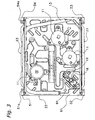
- Figure 3 is a plan view looking downward from a position approximately midway along the height of the outdoor unit.
- the shut-off valves 18, 19 are omitted.
- the internal refrigerant piping is also omitted from the figure.
- the front panel 21, side panel 22, and rear panel 23 of the casing are mounted to the outside of support columns 51, 52, 53, 54.
- the four vertical support columns 51 to 54 are fastened together by the bottom frame 61 located near the bottom end, the horizontal stays 62 and the motor support rack 63 located at a top portion.
- a motor 70 for driving the outdoor fan (not shown) is mounted to the motor support rack 63.
- the support columns 51 to 54 extend downward beyond the bottom frame 61. Thus, a space is formed between the bottom frame 61 and the installation surface (floor surface) after the outdoor unit has been mounted to the installation surface. This space is large enough (high enough) to pass the gaseous refrigerant communication pipe 17a and the liquid refrigerant communication pipe 17b.
- a portion of the bottom end of each support column 51 to 54 is bent inward so as to form a rectangular base foot 51a, 52a, 53a, 54a.
- Each base foot 51a, 52a, 53a, 54a is provided with a through hole for inserting a chemical anchor or the like to secure the outdoor unit 2 to the installation surface.
- the bottom frame 61 supports the compressor 11 and the outdoor heat exchanger 13 and also serves to secure the shut-off valves 18, 19 through a mounting plate 64.
- the bottom frame 61 has an opening in the portion thereof below the shut-off valves 18, 19.
- the gas-side shut-off valve 18 and the liquid-side shut-off valve 19 of the outdoor unit 2 are arranged closely adjacent to each other as shown in Figures 3 and 4.
- the gas-side shut-off valve 18 and the liquid-side shut-off valve 19 are aligned in a direction forming an angle of approximately 45 degrees with respect to the front panel 21 and the side panel 22 of the casing.
- the gas-side shut-off valve 18 and the liquid-side shut-off valve 19 are separated by a distance of L2 and are offset from each other by a distance of L1 in the widthwise direction (horizontal direction parallel to the front panel 21) and also by a distance of L1 in the depthwise direction (horizontal direction parallel to the side panel 22).
- the distance L2 is approximately 1.4 times the distance L1.
- shut-off valves 18, 19 are shown with simplified structures in the figures, the shut-off valves 18, 19 are constructed to connect to the refrigerant communication pipes 17a, 17b with a flare nut (or a flange).
- the gaseous and liquid refrigerant communication pipes 17a, 17b connected to the connecting ports 18a, 19a do not interfere with each other even when they are drawn out in the forward direction with their widthwise positions maintained constant and their height positions (e.g., a position between the installation surface and the bottom frame 61) the same (the double-dot chain lines shown in Figure 4 indicate the pipes 17a, 17b).
- gaseous and liquid refrigerant communication pipes 17a, 17b connected to the connecting ports 18a, 19a do not interfere with each other even when they are drawn out in a sideways direction with their depthwise positions maintained constant and their height positions the same (the double-dot chain lines shown in Figure 4 indicate the pipes 17a, 17b).
- the pipe connecting port of the gas-side shut-off valve and the pipe connecting port of the liquid-side shut-off valve are aligned in either the depthwise direction along the side panel of the casing or the widthwise direction along the front panel of the casing. Consequently, when the connecting ports are aligned in the depthwise direction, the refrigerant communication pipes will interfere with each other if they are drawn out in the depthwise direction at the same height from the connecting ports. Meanwhile, when the connecting ports are aligned in the widthwise direction, the refrigerant communication pipes will interfere with each other if they are drawn out in the widthwise direction at the same height from the connecting ports.
- the pipe connecting port 18a of the gas-side shut-off valve 18 and the pipe connecting port 19a of the liquid-side shut-off valve 19 are offset from each other by a distance L1 in both the depthwise direction and the widthwise direction in a plan view.
- the gaseous and liquid refrigerant communication pipes 17a, 17b do not interfere with each other even when they are drawn out from the connecting ports 18a, 19a in a depthwise direction or a widthwise direction in such a manner that their height positions underneath the bottom frame 61 are the same.
- work associated with bending the refrigerant communication pipes 17a, 17b and using pipe joints can be held to a minimum.
- the pipe connecting port 18a of the gas-side shut-off valve 18 and the pipe connecting port 19a of the liquid-side shut-off valve 19 are offset from each other by the same distance L1 in both the depthwise direction and the widthwise direction.
- the relative distance L2 between the connecting ports 18a, 19a can be reduced and the space occupied by the gas-side shut-off valve 18 and the liquid-side shut-off valve 19 inside the casing can be reduced.
- the work space is the same as in conventional outdoor units because the actual relative distance L2 between the shut-off valves is no smaller than in conventional outdoor units in which the shut-off valves are arranged in the depthwise direction or the widthwise direction; that is, when viewed diagonally the distance between the shut-off valves 18, 19 is the same as in conventional outdoor units.
- the pipe connecting port 18a of the gas-side shut-off valve 18 and the pipe connecting port 19a of the liquid-side shut-off valve 19 both face downward in the same manner. As a result, it is easier to apply thermally insulating tape to both refrigerant communication pipes 17a, 17b at the same time and to cover them with a decorative metal plate.
- the pipe connecting port 18a of the gas-side shut-off valve 18 and the pipe connecting port 19a of the liquid-side shut-off valve 19 both face downward and portions of the support columns 51 to 54 extend downward beyond the bottom frame 61 such that a space is formed between the bottom frame 61 and the surface on which the outdoor unit 2 is installed.
- the refrigerant communication pipes 17a, 17b can be passed through the space and the external appearance of the outdoor unit can be improved.
- the gas-side shut-off valve 18 and the liquid-side shut-off valve 19 are arranged so as to be oriented at a 45-degree angle with respect to both the front panel 21 and the side panel 22 of the casing.
- shut-off valves 18, 19 As shown in Figure 4, however, it is also possible to arrange the shut-off valves 18, 19 as shown in Figure 5.
- the gas-side shut-off valve 18 and the liquid-side shut-off valve 19 are offset from each other by a distance L3 in the widthwise direction (horizontal direction parallel to the front panel 21) and a distance L4 in the depthwise direction (horizontal direction parallel to the side panel 22).
- the distance L3 is set such that when the pipes 17a, 17b are drawn out in the forward direction without bending the pipes to the left or right, the pipes 17a, 17b will be separated from each other and not overlap in a plan view.
- the distance L4 is set to a comparatively small distance such that when the pipes 17a, 17b are drawn out in a sideways direction without bending the pipes to the forward or rearward, the pipes 17a, 17b will partially overlap in a plan view.
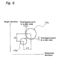
- the centers of the pipes 17a,17b are offset slightly (distance L5) in the height direction, as shown in Figure 6, the pipes 17a, 17b are only partially overlapped in a side view and the heights of the pipes 17a, 17b can be set to be substantially the same. Consequently, the space occupied by the pipes 17a, 17b in the height direction is reduced and the pipes 17a, 17b can be passed through the gap between the bottom frame and the installation surface of the outdoor unit, even when said gap is small.
- the first connecting port and the second connecting port are offset from each other in both the depthwise direction and the widthwise direction of the outdoor unit in a plan view.
- the connecting ports are offset by a sufficient amount that the refrigerant communication pipes do not interfere with each other in a plan view when they are drawn out from the connecting ports in the depthwise direction or in the widthwise direction.
- the refrigerant communication pipes will not interfere with each other in cases where the refrigerant communication pipes are drawn out from the connecting ports in the depthwise direction at the same height or in cases where the refrigerant communication pipes are drawn out from the connecting ports in the widthwise direction at the same height.
Landscapes
- Engineering & Computer Science (AREA)
- Chemical & Material Sciences (AREA)
- Combustion & Propulsion (AREA)
- Mechanical Engineering (AREA)
- General Engineering & Computer Science (AREA)
- Life Sciences & Earth Sciences (AREA)
- Sustainable Development (AREA)
- Other Air-Conditioning Systems (AREA)
Abstract
Description
Claims (6)
- An air conditioner outdoor unit (2) connected to an indoor unit (3) by a gaseous refrigerant communication pipe (17a) and a liquid refrigerant communication pipe (17b), the outdoor unit comprising:a gas-side shut-off valve (18) having a first connecting port (18a) to which the gaseous refrigerant communication pipe (17a) is connected; anda liquid-side shut-off valve (19) having a second connecting port (19a) to which the liquid refrigerant communication pipe (17b) is connected, whereinthe first connecting port (18a) and second connecting port (19a) being, in a plan view, offset from each other in both the depthwise direction and the widthwise direction.
- The air conditioner outdoor unit (2) as recited in claim 1, wherein the first connecting port (18a) and second connecting port (19a) face in the same direction.
- The air conditioner outdoor unit as recited in claim 1 or 2, wherein the first connecting port (18a) and second connecting port (19a) are offset from each other in the depthwise and widthwise directions in such a manner that:the gaseous and liquid refrigerant communication pipes (17a, 17b) connected to the connecting ports do not interfere with each other even when they are drawn out in the depthwise direction with their widthwise positions maintained constant and their height positions arranged such that they overlap partially in a side view; andthe gaseous and liquid refrigerant communication pipes (17a, 17b) connected to the connecting ports do not interfere with each other even when they are drawn out in the widthwise direction with their depthwise positions maintained constant and their height positions arranged such that they overlap partially in a side view.
- The air conditioner outdoor unit (2) as recited in claim 1 or 2, wherein the first connecting port (18a) and second connecting port (19a) are offset from each other in the depthwise and widthwise directions in such a manner that:the gaseous and liquid refrigerant communication pipes (17a, 17b) connected to the connecting ports do not interfere with each other even when they are drawn out in the depthwise direction with their widthwise positions maintained constant and their height positions the same; andthe gaseous and liquid refrigerant communication pipes (17a, 17b) connected to the connecting ports do not interfere with each other even when they are drawn out in the widthwise direction with their depthwise positions maintained constant and their height positions the same.
- The air conditioner outdoor unit (2) as recited in any one of claims 1 to 4, wherein
the first connecting port (18a) and second connecting port (19a) are offset by approximately the same distance (L1) in both the depthwise direction and the widthwise direction. - The air conditioner outdoor unit (2) as recited in any one of claims 1 to 5, wherein
the first connecting port (18a) and second connecting port (19a) face downward; the outdoor unit further comprising:bottom-raising members (51, 52, 53, 54) serving to secure a space between the surface on which the outdoor unit is to be installed and a bottom panel (61) of the casing.a box-shaped casing (21, 22, 23, 61) that covers the gas-side shut-off valve (18) and theliquid-side shut-off valve (19) and has an opening below the gas-side shut-off valve (18)and the liquid-side shut-off valve (19); and
Applications Claiming Priority (3)
| Application Number | Priority Date | Filing Date | Title |
|---|---|---|---|
| JP2002195535A JP3719233B2 (en) | 2002-07-04 | 2002-07-04 | Air conditioner outdoor unit |
| JP2002195535 | 2002-07-04 | ||
| PCT/JP2003/008326 WO2004005805A1 (en) | 2002-07-04 | 2003-06-30 | Outdoor unit of air conditioner |
Publications (3)
| Publication Number | Publication Date |
|---|---|
| EP1521041A1 true EP1521041A1 (en) | 2005-04-06 |
| EP1521041A4 EP1521041A4 (en) | 2008-11-12 |
| EP1521041B1 EP1521041B1 (en) | 2016-09-14 |
Family
ID=30112340
Family Applications (1)
| Application Number | Title | Priority Date | Filing Date |
|---|---|---|---|
| EP03736316.5A Expired - Lifetime EP1521041B1 (en) | 2002-07-04 | 2003-06-30 | Outdoor unit of air conditioner |
Country Status (8)
| Country | Link |
|---|---|
| US (1) | US7086250B2 (en) |
| EP (1) | EP1521041B1 (en) |
| JP (1) | JP3719233B2 (en) |
| KR (1) | KR100578195B1 (en) |
| CN (1) | CN1262798C (en) |
| AU (1) | AU2003244022B2 (en) |
| ES (1) | ES2605400T3 (en) |
| WO (1) | WO2004005805A1 (en) |
Families Citing this family (14)
| Publication number | Priority date | Publication date | Assignee | Title |
|---|---|---|---|---|
| JP3985840B2 (en) | 2005-11-01 | 2007-10-03 | ダイキン工業株式会社 | Air conditioner outdoor unit |
| JP4033218B2 (en) | 2005-11-01 | 2008-01-16 | ダイキン工業株式会社 | Shut-off valve mounting structure, and outdoor unit of air conditioner including the same |
| CN102333996B (en) * | 2009-02-26 | 2014-03-12 | Lg电子株式会社 | Air conditioner and outdoor unit |
| JP5569417B2 (en) * | 2011-01-31 | 2014-08-13 | 株式会社富士通ゼネラル | Air conditioner outdoor unit |
| JP2013113558A (en) * | 2011-11-30 | 2013-06-10 | Daikin Industries Ltd | Outdoor unit of air conditioner and support member for shut-off valve used therefor |
| JP5310829B2 (en) * | 2011-11-30 | 2013-10-09 | ダイキン工業株式会社 | Casing of outdoor unit in air conditioner |
| US9599118B2 (en) | 2013-04-04 | 2017-03-21 | Trane International Inc. | System and method for controlling a system that includes fixed speed and variable speed compressors |
| CN105423452B (en) * | 2014-09-12 | 2019-01-22 | Lg电子株式会社 | The outdoor unit of air regulator |
| KR20160031230A (en) | 2014-09-12 | 2016-03-22 | 엘지전자 주식회사 | An outdoor unit for a an air conditioner |
| KR101753955B1 (en) | 2014-12-17 | 2017-07-05 | 엘지전자 주식회사 | An outdoor unit for a an air conditioner |
| KR101872567B1 (en) | 2015-08-25 | 2018-06-28 | 엘지전자 주식회사 | An outdoor unit for a an air conditioner |
| JP6269717B2 (en) * | 2016-04-21 | 2018-01-31 | ダイキン工業株式会社 | Heat source unit |
| JP2019120449A (en) * | 2017-12-28 | 2019-07-22 | ダイキン工業株式会社 | Heat source unit for refrigeration device |
| JP6673375B2 (en) * | 2018-01-31 | 2020-03-25 | ダイキン工業株式会社 | Air conditioner outdoor unit |
Family Cites Families (17)
| Publication number | Priority date | Publication date | Assignee | Title |
|---|---|---|---|---|
| JPS53104463U (en) * | 1977-01-28 | 1978-08-22 | ||
| JPS53104463A (en) * | 1977-02-23 | 1978-09-11 | Hitachi Ltd | Cold store |
| JPS61101777A (en) | 1984-10-23 | 1986-05-20 | 三菱電機株式会社 | Outdoor machine for air conditioner |
| JPH07816Y2 (en) | 1988-05-23 | 1995-01-11 | ダイキン工業株式会社 | Air conditioner hanging type outdoor unit |
| JPH02106638A (en) * | 1988-10-14 | 1990-04-18 | Matsushita Electric Ind Co Ltd | Separate air conditioner outdoor unit |
| JPH0422667U (en) | 1990-06-18 | 1992-02-25 | ||
| JP3241167B2 (en) | 1993-05-31 | 2001-12-25 | 東芝キヤリア株式会社 | Cabinet for air conditioner |
| JP3285670B2 (en) | 1993-07-15 | 2002-05-27 | 三菱重工業株式会社 | Air conditioner |
| JP3692630B2 (en) * | 1995-10-24 | 2005-09-07 | ダイキン工業株式会社 | Heat transfer device |
| KR0134030Y1 (en) | 1996-07-30 | 1999-05-15 | 구자홍 | Control apparatus for outdoor unit service valve angle of separate type airconditioner |
| JP3807049B2 (en) * | 1997-09-19 | 2006-08-09 | 株式会社富士通ゼネラル | Air conditioner outdoor unit |
| JP3732939B2 (en) | 1998-02-16 | 2006-01-11 | 三洋電機株式会社 | Refrigeration equipment |
| US6170270B1 (en) * | 1999-01-29 | 2001-01-09 | Delaware Capital Formation, Inc. | Refrigeration system using liquid-to-liquid heat transfer for warm liquid defrost |
| US6094925A (en) * | 1999-01-29 | 2000-08-01 | Delaware Capital Formation, Inc. | Crossover warm liquid defrost refrigeration system |
| JP3248512B2 (en) * | 1999-05-11 | 2002-01-21 | 株式会社日立製作所 | Air conditioner |
| JP3460672B2 (en) * | 2000-04-28 | 2003-10-27 | ダイキン工業株式会社 | Outdoor unit of air conditioner and air conditioner |
| EP1340949A4 (en) * | 2000-12-08 | 2009-08-12 | Daikin Ind Ltd | COOLING SYSTEM |
-
2002
- 2002-07-04 JP JP2002195535A patent/JP3719233B2/en not_active Expired - Lifetime
-
2003
- 2003-06-30 AU AU2003244022A patent/AU2003244022B2/en not_active Expired
- 2003-06-30 WO PCT/JP2003/008326 patent/WO2004005805A1/en not_active Ceased
- 2003-06-30 ES ES03736316.5T patent/ES2605400T3/en not_active Expired - Lifetime
- 2003-06-30 US US10/493,862 patent/US7086250B2/en not_active Expired - Lifetime
- 2003-06-30 CN CNB038012820A patent/CN1262798C/en not_active Expired - Lifetime
- 2003-06-30 EP EP03736316.5A patent/EP1521041B1/en not_active Expired - Lifetime
- 2003-06-30 KR KR1020047004149A patent/KR100578195B1/en not_active Expired - Lifetime
Also Published As
| Publication number | Publication date |
|---|---|
| KR20040035860A (en) | 2004-04-29 |
| AU2003244022A1 (en) | 2004-01-23 |
| WO2004005805A1 (en) | 2004-01-15 |
| JP2004037007A (en) | 2004-02-05 |
| ES2605400T3 (en) | 2017-03-14 |
| US20050150247A1 (en) | 2005-07-14 |
| EP1521041A4 (en) | 2008-11-12 |
| KR100578195B1 (en) | 2006-05-11 |
| AU2003244022B2 (en) | 2006-02-02 |
| EP1521041B1 (en) | 2016-09-14 |
| JP3719233B2 (en) | 2005-11-24 |
| CN1568415A (en) | 2005-01-19 |
| CN1262798C (en) | 2006-07-05 |
| US7086250B2 (en) | 2006-08-08 |
Similar Documents
| Publication | Publication Date | Title |
|---|---|---|
| US8297071B2 (en) | Shut-off valve mounting structure, and outdoor unit of air conditioner including the same | |
| KR101595639B1 (en) | Outdoor unit of air conditioner | |
| EP1521041B1 (en) | Outdoor unit of air conditioner | |
| JP4499733B2 (en) | Multi-type air conditioner | |
| JP4482675B2 (en) | Multi-type air conditioner switching unit | |
| CN101300454A (en) | Stop valve mounting structure and outdoor unit of air conditioner having the same | |
| EP3514457B1 (en) | Heat source unit | |
| US12078427B2 (en) | Heat exchanger and air conditioner having the same | |
| EP4283221B1 (en) | Heat exchanger | |
| JP2013076519A (en) | Support member for closing valve in outdoor unit, and outdoor unit including the same | |
| JP7824541B1 (en) | Heat source unit for refrigeration cycle device and refrigeration cycle device | |
| JP2003279075A (en) | Outdoor unit of air-conditioner | |
| WO2026069882A1 (en) | Heat source unit of refrigeration cycle device, and refrigeration cycle device | |
| JP2026058054A (en) | Heat source unit and refrigeration cycle system for refrigeration cycle system | |
| WO2023054224A1 (en) | Cascade unit and refrigeration system | |
| JP2008089258A (en) | Air conditioner outdoor unit | |
| JPH0213737A (en) | Airconditioner |
Legal Events
| Date | Code | Title | Description |
|---|---|---|---|
| PUAI | Public reference made under article 153(3) epc to a published international application that has entered the european phase |
Free format text: ORIGINAL CODE: 0009012 |
|
| 17P | Request for examination filed |
Effective date: 20040527 |
|
| AK | Designated contracting states |
Kind code of ref document: A1 Designated state(s): AT BE BG CH CY CZ DE DK EE ES FI FR GB GR HU IE IT LI LU MC NL PT RO SE SI SK TR |
|
| AX | Request for extension of the european patent |
Extension state: AL LT LV MK |
|
| DAX | Request for extension of the european patent (deleted) | ||
| A4 | Supplementary search report drawn up and despatched |
Effective date: 20081015 |
|
| 17Q | First examination report despatched |
Effective date: 20100121 |
|
| GRAP | Despatch of communication of intention to grant a patent |
Free format text: ORIGINAL CODE: EPIDOSNIGR1 |
|
| INTG | Intention to grant announced |
Effective date: 20160401 |
|
| GRAS | Grant fee paid |
Free format text: ORIGINAL CODE: EPIDOSNIGR3 |
|
| GRAA | (expected) grant |
Free format text: ORIGINAL CODE: 0009210 |
|
| AK | Designated contracting states |
Kind code of ref document: B1 Designated state(s): AT BE BG CH CY CZ DE DK EE ES FI FR GB GR HU IE IT LI LU MC NL PT RO SE SI SK TR |
|
| REG | Reference to a national code |
Ref country code: GB Ref legal event code: FG4D |
|
| REG | Reference to a national code |
Ref country code: CH Ref legal event code: EP |
|
| REG | Reference to a national code |
Ref country code: IE Ref legal event code: FG4D |
|
| REG | Reference to a national code |
Ref country code: AT Ref legal event code: REF Ref document number: 829442 Country of ref document: AT Kind code of ref document: T Effective date: 20161015 |
|
| REG | Reference to a national code |
Ref country code: DE Ref legal event code: R096 Ref document number: 60349391 Country of ref document: DE |
|
| REG | Reference to a national code |
Ref country code: NL Ref legal event code: MP Effective date: 20160914 |
|
| PG25 | Lapsed in a contracting state [announced via postgrant information from national office to epo] |
Ref country code: FI Free format text: LAPSE BECAUSE OF FAILURE TO SUBMIT A TRANSLATION OF THE DESCRIPTION OR TO PAY THE FEE WITHIN THE PRESCRIBED TIME-LIMIT Effective date: 20160914 |
|
| REG | Reference to a national code |
Ref country code: AT Ref legal event code: MK05 Ref document number: 829442 Country of ref document: AT Kind code of ref document: T Effective date: 20160914 |
|
| PG25 | Lapsed in a contracting state [announced via postgrant information from national office to epo] |
Ref country code: NL Free format text: LAPSE BECAUSE OF FAILURE TO SUBMIT A TRANSLATION OF THE DESCRIPTION OR TO PAY THE FEE WITHIN THE PRESCRIBED TIME-LIMIT Effective date: 20160914 Ref country code: SE Free format text: LAPSE BECAUSE OF FAILURE TO SUBMIT A TRANSLATION OF THE DESCRIPTION OR TO PAY THE FEE WITHIN THE PRESCRIBED TIME-LIMIT Effective date: 20160914 Ref country code: GR Free format text: LAPSE BECAUSE OF FAILURE TO SUBMIT A TRANSLATION OF THE DESCRIPTION OR TO PAY THE FEE WITHIN THE PRESCRIBED TIME-LIMIT Effective date: 20161215 |
|
| REG | Reference to a national code |
Ref country code: ES Ref legal event code: FG2A Ref document number: 2605400 Country of ref document: ES Kind code of ref document: T3 Effective date: 20170314 |
|
| PG25 | Lapsed in a contracting state [announced via postgrant information from national office to epo] |
Ref country code: EE Free format text: LAPSE BECAUSE OF FAILURE TO SUBMIT A TRANSLATION OF THE DESCRIPTION OR TO PAY THE FEE WITHIN THE PRESCRIBED TIME-LIMIT Effective date: 20160914 Ref country code: RO Free format text: LAPSE BECAUSE OF FAILURE TO SUBMIT A TRANSLATION OF THE DESCRIPTION OR TO PAY THE FEE WITHIN THE PRESCRIBED TIME-LIMIT Effective date: 20160914 |
|
| PG25 | Lapsed in a contracting state [announced via postgrant information from national office to epo] |
Ref country code: BG Free format text: LAPSE BECAUSE OF FAILURE TO SUBMIT A TRANSLATION OF THE DESCRIPTION OR TO PAY THE FEE WITHIN THE PRESCRIBED TIME-LIMIT Effective date: 20161214 Ref country code: CZ Free format text: LAPSE BECAUSE OF FAILURE TO SUBMIT A TRANSLATION OF THE DESCRIPTION OR TO PAY THE FEE WITHIN THE PRESCRIBED TIME-LIMIT Effective date: 20160914 Ref country code: BE Free format text: LAPSE BECAUSE OF FAILURE TO SUBMIT A TRANSLATION OF THE DESCRIPTION OR TO PAY THE FEE WITHIN THE PRESCRIBED TIME-LIMIT Effective date: 20160914 Ref country code: SK Free format text: LAPSE BECAUSE OF FAILURE TO SUBMIT A TRANSLATION OF THE DESCRIPTION OR TO PAY THE FEE WITHIN THE PRESCRIBED TIME-LIMIT Effective date: 20160914 Ref country code: PT Free format text: LAPSE BECAUSE OF FAILURE TO SUBMIT A TRANSLATION OF THE DESCRIPTION OR TO PAY THE FEE WITHIN THE PRESCRIBED TIME-LIMIT Effective date: 20170116 Ref country code: AT Free format text: LAPSE BECAUSE OF FAILURE TO SUBMIT A TRANSLATION OF THE DESCRIPTION OR TO PAY THE FEE WITHIN THE PRESCRIBED TIME-LIMIT Effective date: 20160914 |
|
| REG | Reference to a national code |
Ref country code: FR Ref legal event code: PLFP Year of fee payment: 15 |
|
| REG | Reference to a national code |
Ref country code: DE Ref legal event code: R097 Ref document number: 60349391 Country of ref document: DE |
|
| PLBE | No opposition filed within time limit |
Free format text: ORIGINAL CODE: 0009261 |
|
| STAA | Information on the status of an ep patent application or granted ep patent |
Free format text: STATUS: NO OPPOSITION FILED WITHIN TIME LIMIT |
|
| PG25 | Lapsed in a contracting state [announced via postgrant information from national office to epo] |
Ref country code: DK Free format text: LAPSE BECAUSE OF FAILURE TO SUBMIT A TRANSLATION OF THE DESCRIPTION OR TO PAY THE FEE WITHIN THE PRESCRIBED TIME-LIMIT Effective date: 20160914 |
|
| 26N | No opposition filed |
Effective date: 20170615 |
|
| PG25 | Lapsed in a contracting state [announced via postgrant information from national office to epo] |
Ref country code: SI Free format text: LAPSE BECAUSE OF FAILURE TO SUBMIT A TRANSLATION OF THE DESCRIPTION OR TO PAY THE FEE WITHIN THE PRESCRIBED TIME-LIMIT Effective date: 20160914 |
|
| PG25 | Lapsed in a contracting state [announced via postgrant information from national office to epo] |
Ref country code: MC Free format text: LAPSE BECAUSE OF FAILURE TO SUBMIT A TRANSLATION OF THE DESCRIPTION OR TO PAY THE FEE WITHIN THE PRESCRIBED TIME-LIMIT Effective date: 20160914 |
|
| REG | Reference to a national code |
Ref country code: CH Ref legal event code: PL |
|
| REG | Reference to a national code |
Ref country code: IE Ref legal event code: MM4A |
|
| PG25 | Lapsed in a contracting state [announced via postgrant information from national office to epo] |
Ref country code: IE Free format text: LAPSE BECAUSE OF NON-PAYMENT OF DUE FEES Effective date: 20170630 Ref country code: CH Free format text: LAPSE BECAUSE OF NON-PAYMENT OF DUE FEES Effective date: 20170630 Ref country code: LU Free format text: LAPSE BECAUSE OF NON-PAYMENT OF DUE FEES Effective date: 20170630 Ref country code: LI Free format text: LAPSE BECAUSE OF NON-PAYMENT OF DUE FEES Effective date: 20170630 |
|
| REG | Reference to a national code |
Ref country code: FR Ref legal event code: PLFP Year of fee payment: 16 |
|
| PG25 | Lapsed in a contracting state [announced via postgrant information from national office to epo] |
Ref country code: HU Free format text: LAPSE BECAUSE OF FAILURE TO SUBMIT A TRANSLATION OF THE DESCRIPTION OR TO PAY THE FEE WITHIN THE PRESCRIBED TIME-LIMIT; INVALID AB INITIO Effective date: 20030630 |
|
| PG25 | Lapsed in a contracting state [announced via postgrant information from national office to epo] |
Ref country code: CY Free format text: LAPSE BECAUSE OF NON-PAYMENT OF DUE FEES Effective date: 20160914 |
|
| PGFP | Annual fee paid to national office [announced via postgrant information from national office to epo] |
Ref country code: IT Payment date: 20220510 Year of fee payment: 20 Ref country code: GB Payment date: 20220512 Year of fee payment: 20 Ref country code: FR Payment date: 20220510 Year of fee payment: 20 Ref country code: DE Payment date: 20220505 Year of fee payment: 20 |
|
| PGFP | Annual fee paid to national office [announced via postgrant information from national office to epo] |
Ref country code: TR Payment date: 20220629 Year of fee payment: 20 |
|
| PGFP | Annual fee paid to national office [announced via postgrant information from national office to epo] |
Ref country code: ES Payment date: 20220701 Year of fee payment: 20 |
|
| REG | Reference to a national code |
Ref country code: DE Ref legal event code: R071 Ref document number: 60349391 Country of ref document: DE |
|
| P01 | Opt-out of the competence of the unified patent court (upc) registered |
Effective date: 20230525 |
|
| REG | Reference to a national code |
Ref country code: GB Ref legal event code: PE20 Expiry date: 20230629 |
|
| REG | Reference to a national code |
Ref country code: ES Ref legal event code: FD2A Effective date: 20230728 |
|
| PG25 | Lapsed in a contracting state [announced via postgrant information from national office to epo] |
Ref country code: GB Free format text: LAPSE BECAUSE OF EXPIRATION OF PROTECTION Effective date: 20230629 Ref country code: ES Free format text: LAPSE BECAUSE OF EXPIRATION OF PROTECTION Effective date: 20230701 |